Asus RS700D-E6/PS8 User Guide
Asus RS700D-E6/PS8 - 0 MB RAM Manual
 |
UPC - 610839680603
View all Asus RS700D-E6/PS8 manuals
Add to My Manuals
Save this manual to your list of manuals |
Asus RS700D-E6/PS8 manual content summary:
- Asus RS700D-E6/PS8 | User Guide - Page 1
RS700D-E6/PS8 RS702D-E6/PS8 RS704D-E6/PS8 1U Rackmount Server User Guide - Asus RS700D-E6/PS8 | User Guide - Page 2
, and should not be construed as a commitment by ASUS. ASUS assumes no responsibility or liability for any errors or inaccuracies that may appear in this manual, including the products and software described in it. Product warranty or service will not be extended if: (1) the product is repaired - Asus RS700D-E6/PS8 | User Guide - Page 3
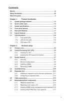
viii About this guide ix Chapter 1: Product card 2-12 2.6 Cable connections 2-13 2.7 Removable/optional components 2-14 2.7.1 Replacing system fans 2-14 2.7.2 Replacing power supply units 2-15 2.7.3 Installing ASMB4 series management board (optional) 2-16 2.7.4 Installing ASUS PIKE Riser Card - Asus RS700D-E6/PS8 | User Guide - Page 4
Internal connectors 4-12 4.4 Internal LEDs 4-20 Chapter 5: BIOS setup 5.1 Managing and updating your BIOS 5-2 5.1.1 AFUDOS utility 5-2 5.1.2 ASUS CrashFree BIOS 3 utility 5-4 5.2 BIOS setup program 5-5 5.2.1 BIOS menu screen 5-6 5.2.2 Menu bar 5-6 5.2.3 Navigation keys 5-6 5.2.4 Menu items - Asus RS700D-E6/PS8 | User Guide - Page 5
Contents 5.4.3 Legacy Device Configuration 5-21 5.4.4 USB Configuration 5-22 5.4.5 PCIPnP Configuration 5-23 5.4.6 Power On configuration 5-24 5.4.7 Event Log Configuration 5-25 5.4.8 Hardware Monitor 5-26 5.4.9 I/O Virtualization 5-27 5.4.10 PCI Express Configuration 5-27 5.4.11 ACPI - Asus RS700D-E6/PS8 | User Guide - Page 6
DDR PCI Gen2 Channel Adapter driver installation (For RS702D-E6/PS8; RS704D-E6/PS8 7-24 7.5.1 7.5.2 Windows operating system 7-24 Red Hat® Enterprise Linux OS 7-27 7.6 Management applications and utilities installation 7-29 7.6.1 Running the support DVD 7-29 7.6.2 Drivers menu 7-29 - Asus RS700D-E6/PS8 | User Guide - Page 7
installed and used in accordance with manufacturer's instructions, may cause harmful interference to radio communications cables for connection of the monitor to the graphics card is required to assure compliance with FCC regulations. ASUS REACH website at http://green.asus.com/english/REACH.htm. vii - Asus RS700D-E6/PS8 | User Guide - Page 8
service technician or your dealer. Operation Safety • Servicing of this product or units is to be performed by trained service personnel only. • Before operating the server, carefully read all the manuals used batteries according to the manufacturer's instructions. CD-ROM Drive Safety Warning CLASS - Asus RS700D-E6/PS8 | User Guide - Page 9
battery should not be placed in municipal waste. About this guide Audience This user guide is intended for system integrators, and experienced users with at parameters. 6. Chapter 6: RAID configuration This chapter provides instructions for setting up, creating and configuring RAID sets using the - Asus RS700D-E6/PS8 | User Guide - Page 10
sources for additional information, and for product and software updates. 1. ASUS Server Web-based Management (ASWM) user guide This manual tells how to set up and use the proprietary ASUS server management utility. 2. ASUS websites The ASUS websites worldwide provide updated information for all - Asus RS700D-E6/PS8 | User Guide - Page 11
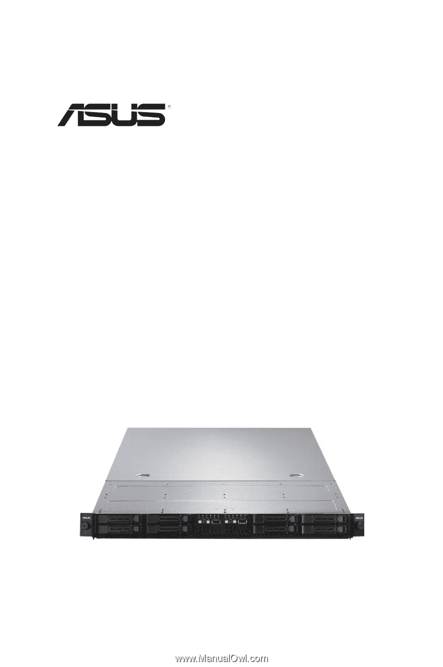
Product introduction Chapter 1 This chapter describes the general features of the server, including sections on front panel and rear panel specifications. ASUS RS700D-E6/PS8, RS702D-E6/PS8, RS704D-E6/PS8 - Asus RS700D-E6/PS8 | User Guide - Page 12
2 x PCI Riser Card (ASUS RE16R-R12B) 2 x Front I/O Board (ASUS FPB-R12A) 1 x Power Distribution Board (ASUS PDB-R12B) 8 x System Fans (40mm x 56mm) Accessories 1 x RS700D-E6/PS8, RS702D-E6/PS8, RS704D-E6/PS8 User's Guide 1 x ASUS ASWM 2.0 User's Guide 1 x 55x0 Series Support CD (including ASWM - Asus RS700D-E6/PS8 | User Guide - Page 13
14 characters such as xxS0xxxxxxxxxx shown as the figure below. With the correct serial number of the product, ASUS Technical Support team members can then offer a quicker and satisfying solution to your problems. RS704D-E6-PS8 xxS0xxxxxxxxxx ASUS RS700D-E6/PS8, RS702D-E6/PS8, RS704D-E6/PS8 1-3 - Asus RS700D-E6/PS8 | User Guide - Page 14
system featuring the ASUS Z8NH-D12 server boards. The ASUS RS702D-E6/PS8 is a 1U barebone server system featuring the ASUS Z8PH-D12/IFB server boards. The ASUS RS704D-E6/PS8 is a 1U barebone server system featuring the ASUS Z8PH-D12 SE/QDR server boards. The servers support Intel® LGA1366 Xeon - Asus RS700D-E6/PS8 | User Guide - Page 15
Model Name RS700D-E6/PS8 RS702D-E6/PS8 RS704D-E6/PS8 Graphic VGA Aspeed AST2050 8MB Onboard I/O OS Support Per Node: Per Node: - 1 x External Serial - 1 x External Band Remote Hardware Software Optional ASMB4-iKVM for KVM-over-IP support ASUS ASWM 2.0® Dimension (HH x WW x DD) 686mm x - Asus RS700D-E6/PS8 | User Guide - Page 16
1.4 Front panel features The barebone server displays a simple yet stylish front panel with easily accessible features. The power and reset buttons, LED indicators, and USB port for each Node are located on the front panel. Refer to section 1.7.1 Front panel LEDs for the LED descriptions. Rack - Asus RS700D-E6/PS8 | User Guide - Page 17
port LAN port 2 LAN port 1 USB ports LAN port* * These ports are for ASUS ASMB4-iKVM controller cards only. ** These ports allow connection with a QSFP cable to an InfiniBand switch. Infiniband plugged in; Data transmitting ACT LED LINK LED ASUS RS700D-E6/PS8, RS702D-E6/PS8, RS704D-E6/PS8 1-7 - Asus RS700D-E6/PS8 | User Guide - Page 18
11 3 3 4 5 67 89 10 10 1. Power supplies and power fans 2. PCI Express x16 slot Riser Cards (at x16 link) 3. ASUS Z8NH-D12 server boards (RS700D-E6/PS4); ASUS Z8PH-D12/IFB server boards (RS702D-E6/PS4) 4. System fans 5. SATA/SAS backplane (hidden) 6. Hot-swap HDD tray 1 and 3-Connect to SATA1 - Asus RS700D-E6/PS8 | User Guide - Page 19
RS704D-E6/PS4 2 2 11 3 3 4 5 67 89 10 10 1. Power supplies and power fans 2. PCI Express x16 slot Riser Cards (at x16 link) 3. ASUS Z8PH-D12 SE/QDR server boards 4. System fans 5. SATA/SAS PARTS KEEP FINGERS AND OTHER BODY PARTS AWAY ASUS RS700D-E6/PS8, RS702D-E6/PS8, RS704D-E6/PS8 1-9 - Asus RS700D-E6/PS8 | User Guide - Page 20
1.7 1.7.1 LED information Front panel LEDs Power LED Message LED Location LED LED Icon Power LED HDD Access LED Message LED Location LED LAN LEDs Display status ON OFF Blinking OFF Blinking OFF ON OFF Blinking ON 1.7.2 LAN (RJ-45) LEDs HDD Access LED LAN2 LED LAN1 LED Description System - Asus RS700D-E6/PS8 | User Guide - Page 21
Hardware setup Chapter 2 This chapter lists the hardware setup procedures that you have to perform when installing or removing system components. ASUS RS700D-E6/PS8, RS702D-E6/PS8, RS704D-E6/PS8 - Asus RS700D-E6/PS8 | User Guide - Page 22
2.1 Chassis cover Removing the rear cover 1. Loosen the two thumbscrews on the rear panel to release the rear cover from the chassis. Thumbscrews 2. Firmly hold the cover and slide it toward the rear panel for about half an inch until it is disengaged from the chassis. 1/2 inch distance 3. Lift the - Asus RS700D-E6/PS8 | User Guide - Page 23
if the damage is shipment/transit-related. • Keep the cap after installing the motherboard. ASUS will process Return Merchandise Authorization (RMA) requests only if the motherboard comes with the cap you and the load lever is on your left. ASUS RS700D-E6/PS8, RS702D-E6/PS8, RS704D-E6/PS8 2-3 - Asus RS700D-E6/PS8 | User Guide - Page 24
2. Press the load lever with your thumb (A), then move it to the left (B) until it is released from the retention tab. To prevent damage to the socket pins, do not remove the PnP cap unless you are installing a CPU. Retention tab A B Load lever 3. Lift the load lever in the direction of the arrow - Asus RS700D-E6/PS8 | User Guide - Page 25
to prevent bending the connectors on the socket and damaging the CPU! CPU notch Alignment key Gold triangle mark 7. Apply several drops of thermal paste to the exposed area of the CPU that lever (B) until it snaps into the retention tab. A ASUS RS700D-E6/PS8, RS702D-E6/PS8, RS704D-E6/PS8 B 2-5 - Asus RS700D-E6/PS8 | User Guide - Page 26
2.2.2 Installing the CPU heatsink and airduct To install the CPU heatsink: 1. Place the heatsink on top of the installed CPU, ensuring that the four fasteners match the holes on the motherboard. 2. Twist each of the four screws with a Philips (cross) screwdriver just enough to attach the heatsink - Asus RS700D-E6/PS8 | User Guide - Page 27
2.3 System memory 2.3.1 Overview The motherboard comes with twelve (12) Double Data Rate 3 (DDR3) Dual Inline Memory Modules (DIMM) sockets. The figure illustrates the location of the DDR3 DIMM sockets: ASUS RS700D-E6/PS8, RS702D-E6/PS8, RS704D-E6/PS8 2-7 - Asus RS700D-E6/PS8 | User Guide - Page 28
from the same vendor. Refer to the Qualified Vendors List on the ASUS web site. • You may install varying memory sizes in Channel A, more details, refer to the Microsoft® support site at http://support.microsoft.com/kb/929605/en-us. • This motherboard does not support DIMMs made up of 256 Mb ( - Asus RS700D-E6/PS8 | User Guide - Page 29
the retaining clips outward to unlock the DIMM. 1 1 DIMM notch Support the DIMM lightly with your fingers when pressing the retaining clips. The DIMM might get damaged when it flips out with extra force. 2. Remove the DIMM from the socket. ASUS RS700D-E6/PS8, RS702D-E6/PS8, RS704D-E6/PS8 2-9 - Asus RS700D-E6/PS8 | User Guide - Page 30
out the lever. 2. Firmly hold the tray lever and pull the drive tray out of the bay. 1 2 3. Remove the drive tray supporting pillar shown in the right figure. Supporting pillar 4. Place a SATAII/SAS hard disk drive on the tray, and then secure it with four screws. 5. Carefully insert the drive - Asus RS700D-E6/PS8 | User Guide - Page 31
, and then secure the card with a screw. PCI Express x16 slot 4. Press the riser card bracket until the golden connectors completely fit the slot and the bracket aligns with the rear panel. 5. Connect the cable(s) to the card, if applicable. ASUS RS700D-E6/PS8, RS702D-E6/PS8, RS704D-E6/PS8 2-11 - Asus RS700D-E6/PS8 | User Guide - Page 32
if any. See Chapter 5 for information on BIOS setup. 2. Assign an IRQ to the card. Refer to the following tables. 3. Install the software drivers for the expansion card. Standard Interrupt assignments IRQ Priority Standard function 0 1 System Timer 1 2 Keyboard Controller 2 - Programmable - Asus RS700D-E6/PS8 | User Guide - Page 33
I/O board) 5. Panel connector (from motherboard to front I/O board) 6. SATA connectors (from motherboard to SATAII/SAS backplane board) 7. Auxiliary panel connector (from motherboard to front I/O board) ASUS RS700D-E6/PS8, RS702D-E6/PS8, RS704D-E6/PS8 2-13 - Asus RS700D-E6/PS8 | User Guide - Page 34
into the system. This section tells how to remove/install the following components: 1. System fans 2. Power supply units 3. ASUS ASMB4-iKVM (optional) 4 ASUS PIKE Riser card (optional) Ensure that the system is turned off before removing any components. 2.7.1 Replacing system fans To uninstall the - Asus RS700D-E6/PS8 | User Guide - Page 35
pull the failed PSU out of the server chassis. 3. Firmly push the new PSU into the chassis until the latch locks to the server chassis. ASUS RS700D-E6/PS8, RS702D-E6/PS8, RS704D-E6/PS8 2-15 - Asus RS700D-E6/PS8 | User Guide - Page 36
below to install an optional ASMB4 series management board on your motherboard. 1. Locate the BMC_FW1 header on the motherboard. 2. Orient and press the ASMB4 management card in place. 3. Insert the LAN cable plug to the LAN3 port for server management. 2-16 Chapter 2: Hardware setup - Asus RS700D-E6/PS8 | User Guide - Page 37
slot on the motherboard. 2. Locate the two screws on the riser card bracket, then remove the screws from the bracket. 3. Locate the two screw holes on the PIKE riser card. 4. Secure the PIKE riser card to the riser card bracket with two screws. ASUS RS700D-E6/PS8, RS702D-E6/PS8, RS704D-E6/PS8 2-17 - Asus RS700D-E6/PS8 | User Guide - Page 38
insert the golden fingers of the PIKE SAS RAID card into the card slot on the PIKE raiser card. Ensure the card is completely seated on the slot. 6. For PIKE 1078 SAS RAID card, snap the i Button into the i Button slot on the PIKE raiser card. 7. Connect the SGPIO cable (preinstalled to the barebone - Asus RS700D-E6/PS8 | User Guide - Page 39
system fans in front of the center mylar. 13. Move the SGPSEL1 jumper on the SATA/SAS backplane to 2-3. If you install two PIKE riser cards in the chassis, move both the jumpers. 14. Place the two system fans back to their default positions. ASUS RS700D-E6/PS8, RS702D-E6/PS8, RS704D-E6/PS8 2-19 - Asus RS700D-E6/PS8 | User Guide - Page 40
2-20 Chapter 2: Hardware setup - Asus RS700D-E6/PS8 | User Guide - Page 41
Installation options Chapter 3 This chapter describes how to install the optional components and devices into the barebone server. ASUS RS700D-E6/PS8, RS702D-E6/PS8, RS704D-E6/PS8 - Asus RS700D-E6/PS8 | User Guide - Page 42
3.1 Rackmount rail kit items (optional) Your rackmount rail kit package contains: • two pair of server rails (for the server) • two pairs of rack rails (for the rack) • Nut-and-bolt type screws Nuts and screws Rear end Front end Rack rails 3.2 Attaching the rails to the server To attach the - Asus RS700D-E6/PS8 | User Guide - Page 43
two rack screws. 8. Secure the rear end of the rail with two rack screws. 9. Repeat steps 5 to 8 to assemble and attach the second rack rail. ASUS RS700D-E6/PS8, RS702D-E6/PS8, RS704D-E6/PS8 3-3 - Asus RS700D-E6/PS8 | User Guide - Page 44
3.4 Rackmounting the server To mount the server to the rack 1. Align the server rails with the rack rails, then push the server all the way to the depth of the rack. 2. Tighten the two rack screws to secure the server in place. To uninstall the server from the rack 1. Loosen the rack screws that - Asus RS700D-E6/PS8 | User Guide - Page 45
Motherboard Info Chapter 4 This chapter includes the motherboard layout and brief descriptions of the jumpers and internal connectors. ASUS RS700D-E6/PS8, RS702D-E6/PS8, RS704D-E6/PS8 - Asus RS700D-E6/PS8 | User Guide - Page 46
4.1 Motherboard layout Z8NH-D12 (For RS700D-E6/PS8) 4-2 Chapter 4: Motherboard information - Asus RS700D-E6/PS8 | User Guide - Page 47
Z8PH-D12/IFB (For RS702D-E6/PS8) ASUS RS700D-E6/PS8, RS702D-E6/PS8, RS704D-E6/PS8 4-3 - Asus RS700D-E6/PS8 | User Guide - Page 48
Z8PH-D12 SE/QDR (For RS704D-E6/PS8) 4-4 Chapter 4: Motherboard information - Asus RS700D-E6/PS8 | User Guide - Page 49
3. Front fan connectors (4-pin FRNT_FAN1, FRNT_FAN2, FRNT_FAN3, FRNT_FAN4) 4. LPC debug card connector (14-1 pin LPC1) 5. Serial General Purpose Input/Output connector (6-1 pin LED 2. CPU warning LED (ERR_CPU1, ERR_CPU2) Page 4-20 4-20 ASUS RS700D-E6/PS8, RS702D-E6/PS8, RS704D-E6/PS8 4-5 - Asus RS700D-E6/PS8 | User Guide - Page 50
4.2 Jumpers 1. Clear RTC RAM (CLRTC1) This jumper allows you to clear the Real Time Clock (RTC) RAM in CMOS. You can clear the CMOS memory of date, time, and system setup parameters by erasing the CMOS RTC RAM data. The onboard button cell battery powers the RAM data in CMOS, which include system - Asus RS700D-E6/PS8 | User Guide - Page 51
2. VGA controller setting (3-pin VGA_SW1) This jumper allows you to enable or disable the onboard VGA controller. Set to pins 1-2 to activate the VGA feature. ASUS RS700D-E6/PS8, RS702D-E6/PS8, RS704D-E6/PS8 4-7 - Asus RS700D-E6/PS8 | User Guide - Page 52
3. DDR3 voltage control setting (4-pin LVDDR3_SEL1; LVDDR3_SEL2) These jumpers allow you to adjust the DIMM voltage. Set to pins 1-2 to select 1.5V BIOS control, pins 2-3 to select 1.2V Force or 3-4 to select 1.35V Force. 4-8 Chapter 4: Motherboard information - Asus RS700D-E6/PS8 | User Guide - Page 53
4. LAN controller setting (3-pin LAN_SW1, LAN_SW2) These jumpers allow you to enable or disable the onboard Intel® Intel 82574LGigabit LAN controllers. Set to pins 1-2 to activate the Gigabit LAN feature. ASUS RS700D-E6/PS8, RS702D-E6/PS8, RS704D-E6/PS8 4-9 - Asus RS700D-E6/PS8 | User Guide - Page 54
5. Intel® ICH10R SATA port S/W RAID setting (3-pin RAID_SEL1) This jumper allows you to select the Serial ATA RAID configuration utility to use when you create disk arrays. Place the jumper caps on pins 1-2 if you want to use the LSI Logic Embedded SATA RAID Setup Utility (default); otherwise, place - Asus RS700D-E6/PS8 | User Guide - Page 55
USB flash and turn on the system to update the BIOS. 4. Shut down the system. 5. Set the jumper back to pins 1-2. 6. Turn on the system. ASUS RS700D-E6/PS8, RS702D-E6/PS8, RS704D-E6/PS8 4-11 - Asus RS700D-E6/PS8 | User Guide - Page 56
4.3 Internal connectors 1. Serial ATA connectors (7-pin SATA1, SATA2, SATA3, SATA4) Supported by the Intel® ICH10R chipset, these connectors are for the Serial ATA signal cables for Serial ATA hard disk drives that allows up to 3Gb/s - Asus RS700D-E6/PS8 | User Guide - Page 57
to connectors USB3, then install the modules to a slot opening at the back of the system chassis. These USB connectors comply with USB 2.0 specification that supports up to 480 Mbps connection speed. ASUS RS700D-E6/PS8, RS702D-E6/PS8, RS704D-E6/PS8 4-13 - Asus RS700D-E6/PS8 | User Guide - Page 58
3. Front fan connectors (4-pin FRNT_FAN1, FRNT_FAN2, FRNT_FAN3, FRNT_FAN4) The fan connectors support cooling fans of 350 mA-740 mA (8.88 W max.) or a total of 3.15 place jumper caps on the fan connectors! • All fans feature the ASUS Smart Fan technology. 4-14 Chapter 4: Motherboard information - Asus RS700D-E6/PS8 | User Guide - Page 59
LPC1) This is a low pin count interface used to plug in the LPC debug card. 5. Serial General Purpose Input/Output connector (6-1 pin SGPIO1) This connector is used for the SGPIO peripherals for the LSI MegaRAID and Intel Matrix RAID SATA LED. ASUS RS700D-E6/PS8, RS702D-E6/PS8, RS704D-E6/PS8 4-15 - Asus RS700D-E6/PS8 | User Guide - Page 60
6. BMC header (BMC_FW1) The BMC connector on the motherboard supports an ASUS® Server Management Board 4 Series (ASMB4). 7. Power Supply SMBus connectors (6-1 pin JP1, JP2) These connectors allow you to connect SMBus (System Management Bus) to the power - Asus RS700D-E6/PS8 | User Guide - Page 61
power is inadequate. • USE THE PROPRIETARY POWER SUPPLY ONLY and ensure that your PSU can provide at least the minimum power required by your system. ASUS RS700D-E6/PS8, RS702D-E6/PS8, RS704D-E6/PS8 4-17 - Asus RS700D-E6/PS8 | User Guide - Page 62
9. System panel connector (20-pin PANEL1) This connector supports several chassis-mounted functions. 1. System power LED (3-pin PLED) This 3-pin connector is for the system power LED. Connect the chassis power LED cable to - Asus RS700D-E6/PS8 | User Guide - Page 63
. 5. Locator Button/Swich (2-pin LOCATORBTN) These leads are for the locator button on the front panel. This button queries the state of the system locator. ASUS RS700D-E6/PS8, RS702D-E6/PS8, RS704D-E6/PS8 4-19 - Asus RS700D-E6/PS8 | User Guide - Page 64
4.4 Internal LEDs 1. Standby Power LED The motherboard comes with a standby power LED. The green LED lights up to indicate that the system is ON, in sleep mode, or in soft-off mode. This is a reminder that you should shut down the system and unplug the power cable before removing or plugging in any - Asus RS700D-E6/PS8 | User Guide - Page 65
BIOS setup Chapter 5 This chapter tells how to change the system settings through the BIOS Setup menus. Detailed descriptions of the BIOS parameters are also provided. ASUS RS700D-E6/PS8, RS702D-E6/PS8, RS704D-E6/PS8 - Asus RS700D-E6/PS8 | User Guide - Page 66
(Updates the BIOS in DOS mode using a bootable USB flash drive.) 2. ASUS CrashFree BIOS 3 (To recover the BIOS using a USB flash drive when the same as shown. 1. Copy the AFUDOS utility (afudos.exe) from the motherboard support CD to the bootable USB flash drive. 2. Boot the system in DOS mode, and - Asus RS700D-E6/PS8 | User Guide - Page 67
power during flash BIOS Reading file ....... done Reading flash ...... done Advance Check ...... Erasing flash ...... done Writing flash ...... done Verifying flash .... done Please restart your computer A:\> ASUS RS700D-E6/PS8, RS702D-E6/PS8, RS704D-E6/PS8 5-3 - Asus RS700D-E6/PS8 | User Guide - Page 68
website. If you want to use the newer BIOS file, download the file at support.asus.com and save it to a USB flash drive. Recovering the BIOS To recover the BIOS 1. Turn on the system. 2. Insert the motherboard support DVD to the optical drive, or the USB flash drive containing the BIOS file - Asus RS700D-E6/PS8 | User Guide - Page 69
5.2 BIOS setup program This motherboard supports a programmable firmware chip that you can update using the match what you see on your screen. • Visit the ASUS website at www.asus.com to download the latest BIOS file for this motherboard. ASUS RS700D-E6/PS8, RS702D-E6/PS8, RS704D-E6/PS8 5-5 - Asus RS700D-E6/PS8 | User Guide - Page 70
5.2.1 BIOS menu screen Menu items Menu bar Configuration fields General help Main Advanced BIOS SETUP UTILITY Server Boot Exit System Time [13:44:30] System Date [Thu, 01/08/2009] SATA 1 SATA 2 SATA 3 SATA 4 : [ST3160812AS] : [Not Detected] : [Not Detected] : [Not Detected] IDE - Asus RS700D-E6/PS8 | User Guide - Page 71
Megatrends, Inc. Scroll bar Pop-up window 5.2.9 General help At the top right corner of the menu screen is a brief description of the selected item. ASUS RS700D-E6/PS8, RS702D-E6/PS8, RS704D-E6/PS8 5-7 - Asus RS700D-E6/PS8 | User Guide - Page 72
Block Mode:16Sectors PIO Mode :4 Async DMA :MultiWord DMA-2 Ultra DMA :Ultra DMA-6 S.M.A.R.T.:Supported Disabled: Disables LBA Mode. Auto: Enables LBA Mode if the device supports it and the devide is not already formatted with LBA Mode disabled. Type [Auto] LBA/Large Mode [Auto] Block - Asus RS700D-E6/PS8 | User Guide - Page 73
or disables the LBA mode. Setting to [Auto] enables the LBA mode if the device supports this mode, and if the device was not previously formatted with LBA mode disabled. Configuration bit data transfer. Configuration options: [Disabled] [Enabled] ASUS RS700D-E6/PS8, RS702D-E6/PS8, RS704D-E6/PS8 5-9 - Asus RS700D-E6/PS8 | User Guide - Page 74
SATA Configuration [Enhanced] Configuration options: [Disabled] [Compatible] [Enhanced] Configure SATA as [IDE] Sets the configuration for the Serial ATA connectors supported by the Southbridge chip. Configuration options: [IDE] [RAID] [AHCI] • If you want to use the Serial ATA hard disk drives as - Asus RS700D-E6/PS8 | User Guide - Page 75
the system. Configuration options: [Auto] [Not Installed] SMART Monitoring [Enabled] Allows you to set the Self-Monitoring, Analysis and Reporting Technology. Configuration options: [Disabled] [Enabled] ASUS RS700D-E6/PS8, RS702D-E6/PS8, RS704D-E6/PS8 5-11 - Asus RS700D-E6/PS8 | User Guide - Page 76
5.3.6 System Information This menu gives you an overview of the general system specifications. The BIOS automatically detects the items in this menu. Main BIOS SETUP UTILITY AMIBIOS Version :0201 Build Date :02/25/10 Processor Speed Count :2400MHZ :1 System Memory Usable Size : 1024MB - Asus RS700D-E6/PS8 | User Guide - Page 77
BIOS automatically detects. Some items may not appear if your CPU does not support the related functions. Advanced BIOS SETUP UTILITY Configure advanced CPU settings Module Version v02.61 (C)Copyright 1985-2009, American Megatrends, Inc. ASUS RS700D-E6/PS8, RS702D-E6/PS8, RS704D-E6/PS8 5-13 - Asus RS700D-E6/PS8 | User Guide - Page 78
keys to adjust the value. Configuration options: [12.0] [13.0] [14.0] [15.0] [16.0] [17.0]] C1E Support [Enabled] Allows you to enable or disable Enhanced Halt State support. Configuration options: [Disabled] [Enabled] Hardware Prefetcher [Enabled] Allows you to enable or disable the Hardware - Asus RS700D-E6/PS8 | User Guide - Page 79
Tech [Enabled] The Intel® C-State Technology allows the CPU to save more power under idle mode. Enable this item only when you install a C-State Technology-supported CPU. Configuration options: [Disabled] [Enabled] ASUS RS700D-E6/PS8, RS702D-E6/PS8, RS704D-E6/PS8 5-15 - Asus RS700D-E6/PS8 | User Guide - Page 80
] [Enabled] C State package limit setting [Auto] We recommend that you set this item to [Auto] for BIOS to automatically detect the C-State mode supported by your CPU. Configuration options: [Auto] [C1] [C3] [C6] C3 Auto Demotion [Enabled] When this item is enabled, the CPU will conditionally demote - Asus RS700D-E6/PS8 | User Guide - Page 81
Below 4GB Channel Interleaving Rank Interleaving Memory Thermal Throttling Force VDD 1.5V [Disabled] [Enabled] [Disabled] [6:1] [4:1] [Disabled] [Disabled] v02.61 (C)Copyright 1985-2009, American Megatrends, Inc. ASUS RS700D-E6/PS8, RS702D-E6/PS8, RS704D-E6/PS8 5-17 - Asus RS700D-E6/PS8 | User Guide - Page 82
CSI Links Speed [Full-Speed] Allows you to set the speed of CSI Links. Configuration options: [Slow-Mode] [Full-Speed] CSI Frequency [Auto] Allows you to set the CSI frequency. Configuration options: [Auto] [4.800GT] [5.866GT] [6.400GT] CSI Isochronous [Disabled] Configuration options: [Disabled] [ - Asus RS700D-E6/PS8 | User Guide - Page 83
The North Bridge Configuration menu shows the auto-detected Northbridge values. Advanced BIOS SETUP UTILITY NorthBridge Chipset Configuration NB Revision :C2 Current CSI Frequency :5.866GT ASUS RS700D-E6/PS8, RS702D-E6/PS8, RS704D-E6/PS8 5-19 - Asus RS700D-E6/PS8 | User Guide - Page 84
South Bridge Chipset Configuration Advanced BIOS SETUP UTILITY CPU Bridge Chipset Configuration USB Functions USB Port Configure USB 2.0 Controller [Enabled] [8+4 USB Ports] [Enabled] SLP_S4# Min. Assertion Width [1 to 2 seconds] Options Disabled Enabled USB Functions [Enabled] Allows - Asus RS700D-E6/PS8 | User Guide - Page 85
] [2E8/IRQ3] Serial Port2 Address [2F8/IRQ3] Allows you to select the Serial Port2 base address. Configuration options: [Disabled] [2F8/IRQ3] [3E8/IRQ4] [2E8/IRQ3] ASUS RS700D-E6/PS8, RS702D-E6/PS8, RS704D-E6/PS8 5-21 - Asus RS700D-E6/PS8 | User Guide - Page 86
of USB devices at startup. If detected, the USB controller legacy mode is enabled. If no USB device is detected, the legacy USB support is disabled. Configuration options: [Disabled] [Enabled] [Auto] The following item appears only when you set USB Function to [Enabled]. USB 2.0 Controller Mode - Asus RS700D-E6/PS8 | User Guide - Page 87
disable the onboard LAN1/2 chip. Configuration: [Disabled] [Enabled] Onboard LAN1/2 Boot [PXE] Allows you to configure the onboard LAN1/2 boot mode. Configuration: [Disabled] [PXE] [iSCSI] ASUS RS700D-E6/PS8, RS702D-E6/PS8, RS704D-E6/PS8 5-23 - Asus RS700D-E6/PS8 | User Guide - Page 88
5.4.6 Power On configuration Advanced BIOS SETUP UTILITY APM Configuration Restore on AC Power Loss [Last State] Resume On Ring [Disabled] Resume On PME#(Wake On LAN) [Disabled] Resume On RTC Alarm [Disabled] Options Power Off Power On Last State ←→ Select Screen ↑↓ Select Item +- Change - Asus RS700D-E6/PS8 | User Guide - Page 89
. View Event Log Press to read all the unread event log. Clear Event Log Press to clear all events on the event log. ASUS RS700D-E6/PS8, RS702D-E6/PS8, RS704D-E6/PS8 5-25 - Asus RS700D-E6/PS8 | User Guide - Page 90
). If the fan is not connected to the motherboard, the field shows [N/A]. Fan Speed Control [High Density Mode] Allows you to configure the ASUS Smart Fan feature that smartly adjusts the fan speeds for more efficient system operation. Configuration options: [Full Speed Mode] [Whisper Mode] [Generic - Asus RS700D-E6/PS8 | User Guide - Page 91
ESC Exit v02.61 (C)Copyright 1985-2009, American Megatrends, Inc. SR-IOV Supported [Disabled] Configuration options: [Disabled] [Enabled] 5.4.10 PCI Express Configuration and L1 link power states. Configuration options: [Disabled] [Enabled] ASUS RS700D-E6/PS8, RS702D-E6/PS8, RS704D-E6/PS8 5-27 - Asus RS700D-E6/PS8 | User Guide - Page 92
v02.61 (C)Copyright 1985-2009, American Megatrends, Inc. Advanced ACPI Configuration Advanced BIOS SETUP UTILITY Advanced ACPI Configuration ACPI 2.0 Support ACPI APIC support BIOS-->AML ACPI table Headless mode [Enabled] [Enabled] [Enabled] [Disabled] Add additional tables as per ACPI - Asus RS700D-E6/PS8 | User Guide - Page 93
Configuration WHEA Support [Enabled] Enable or disable Windows Hardware Error Architecture. WHEA Support [Enabled] Allows you to enable or disable the Windows Hardware Error Architecture (WHEA) support. Configuration options: [Disabled] [Enabled] ASUS RS700D-E6/PS8, RS702D-E6/PS8, RS704D-E6/PS8 - Asus RS700D-E6/PS8 | User Guide - Page 94
5.5 Server menu The Server menu items allow you to customize the server features. Main Advanced Server BIOS SETUP UTILITY Boot Exit Remote Access Configuration IPMI configuration including server monitoring and event log. ←→ Select Screen ↑↓ Select Item Enter Go to Sub Screen F1 General Help - Asus RS700D-E6/PS8 | User Guide - Page 95
[Always]. Configuration options: [Disabled] [Boot Loader] [Always] Terminal Type [VT-UTF8] Allows you to select the target terminal type. Configuration options: [ANSI] [VT100] [VT-UTF8] ASUS RS700D-E6/PS8, RS702D-E6/PS8, RS704D-E6/PS8 5-31 - Asus RS700D-E6/PS8 | User Guide - Page 96
5.6 Boot menu The Boot menu items allow you to change the system boot options. Select an item then press to display the sub-menu. Main Advanced Server BIOS SETUP UTILITY Boot Exit Boot Settings Boot Device Priority Boot Settings Configuration Security Specifies the Boot Device - Asus RS700D-E6/PS8 | User Guide - Page 97
. Configuration options: [Disabled] [Enabled] Set this item to [Enabled] to use the ASUS MyLogo2™ feature. AddOn ROM Display Mode [Force BIOS] Allows you to set the display to trap Interrupt 19. Configuration options: [Disabled] [Enabled] ASUS RS700D-E6/PS8, RS702D-E6/PS8, RS704D-E6/PS8 5-33 - Asus RS700D-E6/PS8 | User Guide - Page 98
5.6.4 Security The Security menu items allow you to change the system security settings. Select an item then press to display the configuration options. BIOS SETUP UTILITY Boot Security Settings Supervisor Password : Not Installed User Password : Not Installed to change - Asus RS700D-E6/PS8 | User Guide - Page 99
accessing the Setup utility. When set to [Always], BIOS checks for user password both when accessing Setup and booting the system. Configuration options: [Setup] [Always] ASUS RS700D-E6/PS8, RS702D-E6/PS8, RS704D-E6/PS8 5-35 - Asus RS700D-E6/PS8 | User Guide - Page 100
5.7 Exit menu The Exit menu items allow you to load the optimal or failsafe default values for the BIOS items, and save or discard your changes to the BIOS items. Main Advanced Server BIOS SETUP UTILITY Boot Exit Exit Options Exit & Save Changes Exit & Discard Changes Discard Changes Load - Asus RS700D-E6/PS8 | User Guide - Page 101
RAID configuration Chapter 6 This chapter provides instructions for setting up, creating and configuring RAID sets using the available utilities. ASUS RS700D-E6/PS8, RS702D-E6/PS8, RS704D-E6/PS8 - Asus RS700D-E6/PS8 | User Guide - Page 102
, and other business systems. Use a minimum of three identical hard disk drives for this setup. 6.1.2 Installing hard disk drives The motherboard supports SATA hard disk drives for RAID set configuration. For optimal performance, install identical drives of the same model and capacity when creating - Asus RS700D-E6/PS8 | User Guide - Page 103
item to [RAID]. 4. Save your changes, and then exit the BIOS Setup. Refer to Chapter 5 for details on entering and navigating through the BIOS Setup. ASUS RS700D-E6/PS8, RS702D-E6/PS8, RS704D-E6/PS8 6-3 - Asus RS700D-E6/PS8 | User Guide - Page 104
set(s) from SATA hard disk drives connected to the SATA connectors supported by the motherboard southbridge chip. To enter the LSI MegaRAID configuration utility, the boot priority of the SATA optical drive has to be manually adjusted. Otherwise, the system will not boot from the connected SATA ODD. - Asus RS700D-E6/PS8 | User Guide - Page 105
Easy Configuration, the virtual drive parameters are set automatically. In New Configuration, you manually set the virtual drive parameters. Using Easy Configuration To create a RAID set using Between Items And Press Enter To Select An Option ASUS RS700D-E6/PS8, RS702D-E6/PS8, RS704D-E6/PS8 6-5 - Asus RS700D-E6/PS8 | User Guide - Page 106
2. The ARRAY SELECTION MENU displays the available drives connected to the SATA ports. Use the up/down arrow key to select the drives you want to include in the RAID set, and then press . When selected, the drive indicator changes from READY to ONLIN A[X]-[Y], where X is the array number, and - Asus RS700D-E6/PS8 | User Guide - Page 107
SPAN = NO RAID Level RAID 0 RAID 1 Choose RAID Level For This VD Cursor Keys, SPACE-(De)Select F2-ChIdInfo F3-SlotInfo F10-Configure Esc-Quit ASUS RS700D-E6/PS8, RS702D-E6/PS8, RS704D-E6/PS8 6-7 - Asus RS700D-E6/PS8 | User Guide - Page 108
8. When creating a RAID 1 or a RAID 10 set, select DWC from the Virtual Drive menu, and then press . When creating a RAID 0 set, proceed to step 10. 9. Select On to enable the Disk Write Cache setting, and then press . LSI Software RAID Configuration Utility Ver A.60 Jul 30, 2008 - Asus RS700D-E6/PS8 | User Guide - Page 109
Drive Rebuild Check Consistency Clear Existing Configuration And Start A New Configuration Use Cursor Keys to Navigate Between Items And Press Enter To Select An Option ASUS RS700D-E6/PS8, RS702D-E6/PS8, RS704D-E6/PS8 6-9 - Asus RS700D-E6/PS8 | User Guide - Page 110
2. Follow step 2 to 7 of the previous section: Using Easy Configuration. 3. Select Size from the Virtual Drive menu, and then press . 4. Key-in the desired virtual drive size, and then press . LSI Software RAID Configuration Utility Ver A.60 Jul 30, 2008 BIOSVViretrusailonDrivAe.(0s8 - Asus RS700D-E6/PS8 | User Guide - Page 111
drive displays at the bottom of the screen. 3. Follow step 3 to 12 of section 6.2.1 Creating a RAID set: Using Easy Configuration to add a new RAID set. ASUS RS700D-E6/PS8, RS702D-E6/PS8, RS704D-E6/PS8 6-11 - Asus RS700D-E6/PS8 | User Guide - Page 112
6.2.3 Initializing the virtual drives After creating the RAID set(s), you must initialize the virtual drives. You may initialize the virtual drives of a RAID set(s) using the Initialize or Objects command on the Management Menu. Using the Initialize command To initialize the virtual drive using the - Asus RS700D-E6/PS8 | User Guide - Page 113
Proce4ss 64 KB Objects Rebuild VD 0 Initialization Complete. Press Esc.. Check Consistency ¦ 100% Completed Virtual Drives Virtual Drive 0 Status ONLINE SPACE-(De)Select, F10-Initialize ASUS RS700D-E6/PS8, RS702D-E6/PS8, RS704D-E6/PS8 6-13 - Asus RS700D-E6/PS8 | User Guide - Page 114
Using the Objects command To initialize the virtual drives using the Objects command 1. From the Management Menu, select Objects > Virtual Drive, and then press . LSI Software RAID Configuration Utility Ver A.60 Jul 30, 2008 BIOS Version A.08.09161344R Objects Management MAednaupter - Asus RS700D-E6/PS8 | User Guide - Page 115
And Press Enter To Select An Option 5. A progress bar appears on screen. If desired, press to abort initialization. When initialization is completed, press . ASUS RS700D-E6/PS8, RS702D-E6/PS8, RS704D-E6/PS8 6-15 - Asus RS700D-E6/PS8 | User Guide - Page 116
6.2.4 Rebuilding failed drives You can manually rebuild failed hard disk drives using the Rebuild command in the Management Menu. To rebuild a failed hard disk drive 1. From the Management Menu, select Rebuild, - Asus RS700D-E6/PS8 | User Guide - Page 117
77247MB HDS728080PLA380 PF20A60A SPACE-(De)Select,F10-Start Rebuild,F2-Drive Information,F3-View Virtual Drives 4. When rebuild is complete, press any key to continue. ASUS RS700D-E6/PS8, RS702D-E6/PS8, RS704D-E6/PS8 6-17 - Asus RS700D-E6/PS8 | User Guide - Page 118
6.2.5 Checking the drives for data consistency You can check and verify the accuracy of data redundancy in the selected virtual drive. The utility can automatically detect and/or detect and correct any differences in data redundancy depending on the selected option in the Objects > Adapter menu. The - Asus RS700D-E6/PS8 | User Guide - Page 119
consistency check. • Abort - Aborts the consistency check. When you restart checking, it continues from zero percent. 5. When checking is complete, press any key to continue. ASUS RS700D-E6/PS8, RS702D-E6/PS8, RS704D-E6/PS8 6-19 - Asus RS700D-E6/PS8 | User Guide - Page 120
Using the Objects command To check data consistency using the Objects command 1. From the Management Menu, select Objects, and then select Virtual Drive from the sub-menu. 2. Use the arrow keys to select the virtual drive you want to check, and then press . 3. Select Check Consistency from - Asus RS700D-E6/PS8 | User Guide - Page 121
Cursor Keys To Navigate Between Items And Press Enter To Select An Option The utility clears all the current array(s). 3. Press any key to continue. ASUS RS700D-E6/PS8, RS702D-E6/PS8, RS704D-E6/PS8 6-21 - Asus RS700D-E6/PS8 | User Guide - Page 122
6.2.7 Selecting the boot drive from a RAID set You must have created a new RAID configuration before you can select the boot drive from a RAID set. See section 6.2.1 Creating a RAID set: Using New Configuration for details. To select the boot drive from a RAID set 1. From the Management Menu, - Asus RS700D-E6/PS8 | User Guide - Page 123
6.2.8 Enabling WriteCache You may manually enable the RAID controller's WriteCache option after creating a RAID set to improve the data transmission Items And Press Enter To Select An Option 5. When finished, press any key to continue. ASUS RS700D-E6/PS8, RS702D-E6/PS8, RS704D-E6/PS8 6-23 - Asus RS700D-E6/PS8 | User Guide - Page 124
create RAID 0, RAID 1, RAID 10 (RAID 1+0), and RAID 5 set(s) from Serial ATA hard disk drives that are connected to the Serial ATA connectors supported by the Southbridge. To enter the Intel® Matrix Storage Manager option ROM utility: 1. Install all the Serial ATA hard disk drives. 2. Turn on the - Asus RS700D-E6/PS8 | User Guide - Page 125
up/down arrow key to select a drive, and then press to select. A small triangle marks the selected drive. Press after completing your selection. ASUS RS700D-E6/PS8, RS702D-E6/PS8, RS704D-E6/PS8 6-25 - Asus RS700D-E6/PS8 | User Guide - Page 126
6. Use the up/down arrow key to select the stripe size for the RAID array (for RAID 0, 10 and 5 only), and then press . The available stripe size values range from 4 KB to 128 KB. The following are typical values: RAID 0: 128KB RAID 10: 64KB RAID 5: 64KB We recommend a lower stripe size for - Asus RS700D-E6/PS8 | User Guide - Page 127
VOLUME menu. If a recovery set is created, you cannot add more RAID sets even when you have more non-RAID disks installed in your system. ASUS RS700D-E6/PS8, RS702D-E6/PS8, RS704D-E6/PS8 6-27 - Asus RS700D-E6/PS8 | User Guide - Page 128
6.3.3 Deleting a RAID set Take caution when deleting a RAID set. You will lose all data on the hard disk drives when you delete a RAID set. To delete a RAID set 1. From the utility main menu, select 2. Delete RAID Volume and press . The following screen appears. Intel(R) Matrix Storage - Asus RS700D-E6/PS8 | User Guide - Page 129
. 3. Press to reset the RAID set drive(s). A confirmation message appears. 4. Press to reset the drive(s) or press to return to the utility main menu. ASUS RS700D-E6/PS8, RS702D-E6/PS8, RS704D-E6/PS8 6-29 - Asus RS700D-E6/PS8 | User Guide - Page 130
6.3.5 Recovery Volume Options If you have created a recovery set, you can configure more recovery set options following the descriptions in the section. See section 6.3.2 Creating a Recovery set to create a recovery set before continue. To configure a recovery set 1. From the utility main menu, - Asus RS700D-E6/PS8 | User Guide - Page 131
Model Serial # Size X XXXXXXXXXXX XXXXXXXX XX.XGB [↑↓]-Previous/Next [ENTER]-Select [ESC]-Exit Select a destination disk with the same size as the original hard disk. ASUS RS700D-E6/PS8, RS702D-E6/PS8, RS704D-E6/PS8 6-31 - Asus RS700D-E6/PS8 | User Guide - Page 132
3. The utility immediately starts rebuilding after the disk is selected. The status of the degraded RAID volume is changed to "Rebuild". Intel(R) Matrix Storage Manager option ROM v8.5.0.1030 ICH10R/DO wRAID5 Copyright(C) 2003-08 Intel Corporation. All Rights Reserved. [ MAIN MENU ] 1. Create - Asus RS700D-E6/PS8 | User Guide - Page 133
Device Priority for details. 4. From the Exit menu, select Exit & Save Changes, then press . 5. When the confirmation window appears, select OK, then press . ASUS RS700D-E6/PS8, RS702D-E6/PS8, RS704D-E6/PS8 6-33 - Asus RS700D-E6/PS8 | User Guide - Page 134
6-34 Chapter 6: RAID configuration - Asus RS700D-E6/PS8 | User Guide - Page 135
Driver installation Chapter 7 This chapter provides instructions for installing the necessary drivers for different system components. ASUS RS700D-E6/PS8, RS702D-E6/PS8, RS704D-E6/PS8 - Asus RS700D-E6/PS8 | User Guide - Page 136
drive or bootable array. This part provides instructions on how to install the RAID controller of the SATA optical disk drive has to be manually adjusted. Otherwise, the system will not boot from drive as the first boot priority to boot from the support DVD. Save your changes, and then exit the - Asus RS700D-E6/PS8 | User Guide - Page 137
SP2 64 bit Back Exit 6. Locate the RAID driver and place a blank, high-density floppy disk to the floppy disk drive. 7. Press . 8. Follow screen instructions to create the driver disk. ASUS RS700D-E6/PS8, RS702D-E6/PS8, RS704D-E6/PS8 7-3 - Asus RS700D-E6/PS8 | User Guide - Page 138
1. Start Windows®. 2. Place the motherboard support DVD into the optical drive. 3. Go to the Make Disk menu, and then select the type of RAID driver disk you want to create. 4. Insert a floppy disk into the floppy disk drive. 5. Follow succeeding screen instructions to complete the process. Write - Asus RS700D-E6/PS8 | User Guide - Page 139
, press S. * If you do not have any device support disks from a mass storage device manufacturer, or do not want to specify additional mass storage devices for use with Windows, press ENTER. S=Specify Additional Device ENTER=Continue F3=Exit ASUS RS700D-E6/PS8, RS702D-E6/PS8, RS704D-E6/PS8 7-5 - Asus RS700D-E6/PS8 | User Guide - Page 140
Enter>. Windows Setup Please insert the disk labeled Manufacturer-supplied hardware support disk into Drive A: * Press ENTER when ready. ENTER=Continue . 7. Setup then proceeds with the OS installation. Follow screen instructions to continue. To an existing Windows® Server OS To install the - Asus RS700D-E6/PS8 | User Guide - Page 141
Properties from the menu. 5. Click the Driver tab, and then click the Driver Details button to display the RAID controller drivers. 6. Click OK when finished. ASUS RS700D-E6/PS8, RS702D-E6/PS8, RS704D-E6/PS8 7-7 - Asus RS700D-E6/PS8 | User Guide - Page 142
Red Hat® Enterprise Linux OS 4.7/4.8 To install the RAID controller driver when installing�R��e�d�H��a�t® Enterprise OS: 1. Boot the system from the Red Hat® OS installation CD. 2. At the boot:, type linux dd nostorage. 3. Press . - To install or upgrade in graphical mode, press the - Asus RS700D-E6/PS8 | User Guide - Page 143
press to continue. Keyboard Type What type of keyboard do you have? trq ua ua-utf # ua-utf-ws uk unicode us OK Back ASUS RS700D-E6/PS8, RS702D-E6/PS8, RS704D-E6/PS8 7-9 - Asus RS700D-E6/PS8 | User Guide - Page 144
OK. Press to continue. No driver found Unable to find any devices of the type needed for this installation type. Would you like to manually select your driver or use a driver disk? Select driver Use a driver disk Back 7-10 Chapter 7: Driver installation - Asus RS700D-E6/PS8 | User Guide - Page 145
. CD Found To begin testing the CD media before installation press OK. Choose Skip to skip the media test and start the installation. OK Skip ASUS RS700D-E6/PS8, RS702D-E6/PS8, RS704D-E6/PS8 7-11 - Asus RS700D-E6/PS8 | User Guide - Page 146
(megasr) USB Mass Storage driver for Linux (usb-storage) Done Add Device The displayed devices may vary with models and systems. 14. Follow the onscreen instructions to finish installing the RedHat operating system. 7-12 Chapter 7: Driver installation - Asus RS700D-E6/PS8 | User Guide - Page 147
>. Driver Disk Source You have multiple devices which could serve as sources for a driver disk. Which would you like to use? fd0 scd0 OK Cancel ASUS RS700D-E6/PS8, RS702D-E6/PS8, RS704D-E6/PS8 7-13 - Asus RS700D-E6/PS8 | User Guide - Page 148
and press "OK" to continue. OK Back The drivers for the RAID card are installed to the system. 7. When asked if you will load additional RAID you wish to load any more driver disks? Yes No 8. Follow the onscreen instructions to finish the OS installation. 9. If you install RHEL AS5, when the - Asus RS700D-E6/PS8 | User Guide - Page 149
APIC Disabled Installation--Safe Settings Rescue System Memory Test Boot Options | Yes No File F1 Help F2 Language F3 1280 x 1024 F4 DVD F5 Driver ASUS RS700D-E6/PS8, RS702D-E6/PS8, RS704D-E6/PS8 7-15 - Asus RS700D-E6/PS8 | User Guide - Page 150
4. Insert the RAID driver disk to the floppy disk drive. Make sure that Installation from the Boot Options menu is selected, then press . Boot from Hard Disk Installation Installation--ACPI Disabled Installation--Local APIC Disabled Installation--Safe Settings Rescue System Memory Test Boot - Asus RS700D-E6/PS8 | User Guide - Page 151
. The support DVD automatically displays the Drivers menu if Autorun is enabled in your computer. 3. Click the item Intel Chipset Device Software from the menu. 4. The Intel(R) Chipset Device Software window appears. Click Next to start installation. ASUS RS700D-E6/PS8, RS702D-E6/PS8, RS704D-E6/PS8 - Asus RS700D-E6/PS8 | User Guide - Page 152
5. Select Yes to accept the terms of the License Agreement and continue the process. 6. Read the Readme File Information and press Next to continue the installation. 7. After completing the installation, click Finish to complete the setup process. 7-18 Chapter 7: Driver installation - Asus RS700D-E6/PS8 | User Guide - Page 153
the support DVD to locate the file ASSETUP.EXE from the BIN folder. Doubleclick the ASSETUP.EXE to run the DVD. 3. Click the Intel Network Connections Software to begin installation. 4. Click Install Drivers and Software option to begin installation. ASUS RS700D-E6/PS8, RS702D-E6/PS8, RS704D-E6/PS8 - Asus RS700D-E6/PS8 | User Guide - Page 154
5. Click Next when the Intel(R) Network Connections-InstallShield Wizard window appears. 6. Toggle I accept the terms in the license agreement and click Next to continue. 7. Click the Intel(R) PROSet for Windows Device Manager box, and then click Next to start the installation. 7-20 Chapter 7: - Asus RS700D-E6/PS8 | User Guide - Page 155
8. Follow the screen instructions to complete installation. 9. When finished, press Finish to continue. ASUS RS700D-E6/PS8, RS702D-E6/PS8, RS704D-E6/PS8 7-21 - Asus RS700D-E6/PS8 | User Guide - Page 156
This section provides instructions on how to install the Aspeed® Video Graphics Adapter (VGA) driver. You need to manually install the Aspeed® Administrator privileges. 2. Insert the motherboard/system support DVD to the optical drive. The support DVD automatically displays the Drivers menu if - Asus RS700D-E6/PS8 | User Guide - Page 157
4. Click Install to update the VGA driver. 5. When the installation completes, click Finish to restart your computer before using the program. ASUS RS700D-E6/PS8, RS702D-E6/PS8, RS704D-E6/PS8 7-23 - Asus RS700D-E6/PS8 | User Guide - Page 158
Mellanox ConnectX DDR PCI Gen2 Channel Adapter driver installation (For RS702D-E6/PS8; RS704D-E6/PS8) This section provides instructions on how to install the Mellanox driver. 7.5.1 Windows operating system You need to manually install the Mellanox driver on a Windows® operating system. To install - Asus RS700D-E6/PS8 | User Guide - Page 159
5. Click I accept the terms in the license agreement and click Next to continue. 6. Click Change to select your desired destination folder and click Next to continue. 7. Select a setup type and click Next to continue. ASUS RS700D-E6/PS8, RS702D-E6/PS8, RS704D-E6/PS8 7-25 - Asus RS700D-E6/PS8 | User Guide - Page 160
8. The driver features you selected are being installed. 9. Click your preferred options and click Finish to exit the wizard. 7-26 Chapter 7: Driver installation - Asus RS700D-E6/PS8 | User Guide - Page 161
Linux OS You need to manually mount the Mellanox driver on a Red Hat® Enterprise Linux OS. For users using SUSE Linux Enterprise Server OS, follow the general instructions in this section to mount Type the command line and install the driver. ASUS RS700D-E6/PS8, RS702D-E6/PS8, RS704D-E6/PS8 7-27 - Asus RS700D-E6/PS8 | User Guide - Page 162
5. All other Mellanox, OEM, OFED, or distribution IB packages will be removevd. Press to continue. 6. The system starts uninstalling the previous version of OFED. 7. When the installation finishes, reboot your system to complete the installation. If your system has the latest firmware, no - Asus RS700D-E6/PS8 | User Guide - Page 163
of the support DVD are subject to change at any time without notice. Visit the ASUS website (www.asus.com) for updates. 7.6.1 Running the support DVD Place the support DVD to the driver options vary under different operating system versions. ASUS RS700D-E6/PS8, RS702D-E6/PS8, RS704D-E6/PS8 7-29 - Asus RS700D-E6/PS8 | User Guide - Page 164
The Utilities menu displays the software applications and utilities that the motherboard supports. Click an item to install. 7.6.4 Make disk menu The Make Click the Contact tab to display the ASUS contact information. You can also find this information on the inside front cover of this
-
 1
1 -
 2
2 -
 3
3 -
 4
4 -
 5
5 -
 6
6 -
 7
7 -
8
-
9
-
10
-
11
-
12
-
13
-
14
-
15
-
16
-
17
-
18
-
19
-
20
-
21
-
22
-
23
-
24
-
25
-
26
-
27
-
28
-
29
-
30
-
31
-
32
-
33
-
34
-
35
-
36
-
37
-
38
-
39
-
40
-
41
-
42
-
43
-
44
-
45
-
46
-
47
-
48
-
49
-
50
-
51
-
52
-
53
-
54
-
55
-
56
-
57
-
58
-
59
-
60
-
61
-
62
-
63
-
64
-
65
-
66
-
67
-
68
-
69
-
70
-
71
-
72
-
73
-
74
-
75
-
76
-
77
-
78
-
79
-
80
-
81
-
82
-
83
-
84
-
85
-
86
-
87
-
88
-
89
-
90
-
91
-
92
-
93
-
94
-
95
-
96
-
97
-
98
-
99
-
100
-
101
-
102
-
103
-
104
-
105
-
106
-
107
-
108
-
109
-
110
-
111
-
112
-
113
-
114
-
115
-
116
-
117
-
118
-
119
-
120
-
121
-
122
-
123
-
124
-
125
-
126
-
127
-
128
-
129
-
130
-
131
-
132
-
133
-
134
-
135
-
136
-
137
-
138
-
139
-
140
-
141
-
142
-
143
-
144
-
145
-
146
-
147
-
148
-
149
-
150
-
151
-
152
-
153
-
154
-
155
-
156
-
157
-
158
-
159
-
160
-
161
-
162
-
163
-
164
 |
 |
RS700D-E6/PS8
RS702D-E6/PS8
RS704D-E6/PS8
1U Rackmount Server
User Guide