Asus RS720Q-E11-RS8U User Manual
Asus RS720Q-E11-RS8U Manual
 |
View all Asus RS720Q-E11-RS8U manuals
Add to My Manuals
Save this manual to your list of manuals |
Asus RS720Q-E11-RS8U manual content summary:
- Asus RS720Q-E11-RS8U | User Manual - Page 1
RS720Q-E11-RS8U 2U Rackmount Server User Guide - Asus RS720Q-E11-RS8U | User Manual - Page 2
. ASUS assumes no responsibility or liability for any errors or inaccuracies that may appear in this manual, including the products and software described in it. Product warranty or service will not be extended if: (1) the product is repaired, modified or altered, unless such repair, modification - Asus RS720Q-E11-RS8U | User Manual - Page 3
Contents Safety information...vii About this guide...ix Chapter 1: Product Introduction 1.1 System package contents 1-2 1.2 Serial number label 1-3 1.3 System specifications 1-4 1.4 Front panel features 1-6 1.5 Rear panel features 1-7 1.6 Internal features 1-8 1.7 LED information 1-9 - Asus RS720Q-E11-RS8U | User Manual - Page 4
Contents 2.6 Expansion slots 2-20 2.6.1 Installing a PCIe expansion card 2-20 2.6.2 Configuring an expansion card 2-24 2.6.3 Installing an M.2 card 2-25 2.7 Backplane and Midplane cabling 2-28 2.8 Removable/optional components 2-31 2.8.1 System fan 2-31 2.8.2 Power supply module 2-34 - Asus RS720Q-E11-RS8U | User Manual - Page 5
24 5.5.1 PCH-IO Configuration 5-25 5.5.2 Miscellaneous Configuration 5-26 5.5.3 Server ME Configuration 5-26 5.5.4 Runtime Error Logging Support 5-27 5.6 Socket Configuration menu 5-28 5.6.1 Processor Configuration 5-29 5.6.2 Common RefCode Configuration 5-35 5.6.3 Uncore Configuration 5-35 - Asus RS720Q-E11-RS8U | User Manual - Page 6
.2 View FRU Information 5-53 5.11.3 BMC network configuration 5-54 5.11.4 View System Event Log 5-56 5.12 Save & Exit menu 5-57 Chapter 6: Driver Installation 6.1 Running the Support DVD 6-2 Appendix Z13PH-D16 block diagram A-2 Notices ...A-3 Service and Support A-5 vi - Asus RS720Q-E11-RS8U | User Manual - Page 7
engineers. • Before operating the server, carefully read all the manuals included with the server package. • Before using the server, ensure Room where: • Access can only be gained by SERVICE PERSONS or by USERS who have been instructed about the reasons for the restrictions applied to the - Asus RS720Q-E11-RS8U | User Manual - Page 8
Replace only with the same or equivalent type recommended by the manufacturer. Dispose of used batteries according to the manufacturer's instructions. Avertissement sur les batteries Lithium-Ion ATTENTION : Danger d'explosion si la batterie n'est pas correctement remplacée. Remplacer uniquement avec - Asus RS720Q-E11-RS8U | User Manual - Page 9
users with at least basic knowledge of configuring a server. Contents This guide contains the following parts: 1. Chapter 1: Product Introduction This chapter describes 6: Driver Installation This chapter provides instructions for installing the necessary drivers for different system components. ix - Asus RS720Q-E11-RS8U | User Manual - Page 10
manual. DANGER/WARNING: Information to prevent injury to yourself when trying to complete a task. CAUTION: Information to prevent damage to the components when trying to complete a task. IMPORTANT: Instructions 1. ASUS Control Center (ACC) user guide This manual tells how to set up and use the - Asus RS720Q-E11-RS8U | User Manual - Page 11
Chapter 1: Product Introduction Product Introduction This chapter describes the general features of the server. It includes sections on front panel and rear panel specifications. 1 - Asus RS720Q-E11-RS8U | User Manual - Page 12
Fans (40mm x 28mm) 4 x System Fans (80mm x 38mm) 8 x Tool-less Hot-swap 2.5" Storage Bays 1 x ASUS RS720Q-E11-RS8U Series Support DVD (includes User Guide) 8 x CPU Standard Heatsinks (air cooling SKUs only) 4 x CPU Cold Plate Loop (liquid cooling SKUs only) 1 x Bag of Screws Accessories - Asus RS720Q-E11-RS8U | User Manual - Page 13
number contains 12 characters such as xxSxxxxxxxxx similar to the figure shown below. You need to provide the correct serial number to the ASUS Technical Support team member if you need assistance or when requesting - Asus RS720Q-E11-RS8U | User Manual - Page 14
, 256GB, 128GB Intel® Optane™ DC persistent memory 300 Series (Crow Pass) Expansion Slots Total PCI/ PCIe Slots Slot Type M.2 * Refer to www.asus.com/support for the latest update 2 PCIe slots per Node Per Node: 2 x PCIe x16 (Gen5 x16 link), LP, HHHL (CPU1) Per Node: 2 x M.2 (Up to 22110, PCIe - Asus RS720Q-E11-RS8U | User Manual - Page 15
Rear: - 1 x Power Switch/LED - 1 x Q-Code/Port 80 LED Security Options TPM-SPI / PFR Management Solution Software Out of Band Remote Management OS support ASUS Control Center (Classic) On-Board ASMB11-iKVM for KVM-over-IP Windows® Server, RHEL, SLES, CentOS, Ubuntu * Refer to www.asus.com - Asus RS720Q-E11-RS8U | User Manual - Page 16
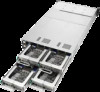
1.4 Front panel features The barebone server displays easily accessible features such as the power and reset buttons, LED indicators, and optical drive. Refer to the Front panel LEDs section for the LED descriptions. Front panel Node 2 Node 1 (Bay 1 - 2) Node 3 (Bay 5 - 6) Front panel Node 4 - Asus RS720Q-E11-RS8U | User Manual - Page 17
1.5 Rear panel features RS720Q-E11-RS8U PSU 2 Node 4 Node 2 PSU 1 Node 3 Node 1 When installing only two nodes, install the nodes to node slot number 1 and 2 or number 3 and 4. Z13PH-D16 (Node) Expansion slot Expansion slot Q-Code/Port 80 LED Power button X710 LAN ports USB 3.2 Gen 1 - Asus RS720Q-E11-RS8U | User Manual - Page 18
1.6 Internal features The barebone server includes the basic components as shown. 1. Front Panel Boards 2. Hot-swap storage device trays 3. HDD Backplane 4. System fan (SYS_FAN1) 5. System fan (SYS_FAN2) 6. System fan (SYS_FAN3) 7. System fan (SYS_FAN4) 8. BP_FAN1 (top) and BP_FAN2 (bottom) 9. - Asus RS720Q-E11-RS8U | User Manual - Page 19
1.7 LED information 1.7.1 Front panel LEDs Power button with LED Message LED Message LED Power button with LED X710 LAN1 LED Location button with LED X710 LAN2 LED 1 2 1 2 X710 LAN2 LED Location button with LED X710 LAN1 LED LED Icon Power LED Message LED LAN LEDs Location LED - Asus RS720Q-E11-RS8U | User Manual - Page 20
1.7.2 HDD status LEDs Status Activity Storage Device LED Description Status (RED) ON Blinking Storage device has failed RAID rebuilding or locating ON Storage device power ON Activity (GREEN) Blinking Read/write data from/into the SATA/SAS/NVMe storage device OFF Storage device not found - Asus RS720Q-E11-RS8U | User Manual - Page 21
1.7.3 LAN (RJ-45) LEDs Dedicated Management LAN port (DM_LAN1) LED indications ACT/LINK LED SPEED LED ACT/LINK LED Status Description OFF No link GREEN Linked BLINKING Data activity Intel® X710-AT2 10GbE LAN port LEDs ACT/LINK LED SPEED LED SPEED LED Status Description OFF 10 Mbps - Asus RS720Q-E11-RS8U | User Manual - Page 22
1.7.4 Rear panel LEDs Q-Code/Port 80 LED Power button with LED BMC Message LED CATERR LED Standby Power LED BMC Heartbeat LED BMC Location LED LED Display status Description Power LED ON System power is on BMC Heartbeat LED Blinking BMC is operating normally BMC Location LED OFF ON - Asus RS720Q-E11-RS8U | User Manual - Page 23
Action Normal boot PHASE POST CODE BB BC BF 5A PEI(Pre-EFI initialization) phase 31 32 34 36 4F 60 61 62 63 68 DXE(Driver 69 Execution Environment) phase 6A 70 71 72 78 79 90 91 92 93 94 95 96 97 98 99 9A 9B 9C BDS(Boot Device 9D Selection) phase b2 b3 b4 b6 - Asus RS720Q-E11-RS8U | User Manual - Page 24
1-14 Chapter 1: Product Introduction - Asus RS720Q-E11-RS8U | User Manual - Page 25
Chapter 2: Hardware Information Hardware Information This chapter lists the hardware setup procedures that you have to perform when installing or removing system components. 2 - Asus RS720Q-E11-RS8U | User Manual - Page 26
2.1 Server node 2.1.1 Removing a server node 1. Remove the screw located on the node latch. 2. Hold the server node lever and press the green node latch. 3. Firmly pull the server node out of the server chassis. 2-2 Chapter 2: Hardware Information - Asus RS720Q-E11-RS8U | User Manual - Page 27
2.1.2 Installing a server node When installing only two nodes, install the nodes to node slot number 1 and 3 or number 2 and 4. Refer to the Rear panel features section for details. 1. Align the node with the node slot on the chassis, then push the node all the way into the node slot. 2. Secure the - Asus RS720Q-E11-RS8U | User Manual - Page 28
2.2 Air Duct The RS720Q-E11-RS8U server system comes with a motherboard fan air duct to enable better air flow inside the motherboard while the system is running. 2.2.1 Removing the air duct 1. Remove the three (3) screws securing the air duct on both sides of the node chassis. 2. Carefully lift the - Asus RS720Q-E11-RS8U | User Manual - Page 29
2.3 Central Processing Unit (CPU) The motherboard comes with a surface mount LGA 4677 socket designed for the 4th Gen Intel® Xeon® Processor Scalable Family processors. • Upon purchase of the motherboard, ensure that the PnP cap is on the socket and the socket contacts are not bent. Contact your - Asus RS720Q-E11-RS8U | User Manual - Page 30
4. Attach the CPU to the carrier bracket, ensure the triangle mark is on the same side as the bracket lever, then attach the CPU and carrier bracket to the heatsink. The CPU carrier differs depending on the type of CPU. Ensure that the CPU carrier corresponds to the CPU being installed. 2-6 - Asus RS720Q-E11-RS8U | User Manual - Page 31
5. Align the CPU and heatsink assembly in the correct orientation so that the triangle marks on both the CPU and socket are aligned in the same direction, then place the heatsinks on top of the CPU sockets. The CPU and CPU Carrier fits in only one correct orientation. DO NOT force the CPU and CPU - Asus RS720Q-E11-RS8U | User Manual - Page 32
6. Once the heatsink is placed on top of the CPU socket (A), push the lock latches outwards on all four corners of the heatsink so that the heatsink and CPU assembly is secured to the CPU socket (B). Ensure the triangle mark on the CPU is located in the same corner as the CPU socket. 7. Do two (2) - Asus RS720Q-E11-RS8U | User Manual - Page 33
2.3.2 Installing the CPU and liquid cooling module To install the CPUs and liquid cooling module: 1. Remove the server node. For more information, see the Removing a server node section. 2. Remove the air duct. For more information, see the Removing the air duct section. 3. Attach the CPU to the - Asus RS720Q-E11-RS8U | User Manual - Page 34
6. Remove the PnP caps from the CPU sockets. Keep the PnP cap. ASUS will process Return Merchandise Authorization (RMA) requests only if the motherboard comes with the PnP cap on the socket. 2-10 Chapter 2: Hardware Information - Asus RS720Q-E11-RS8U | User Manual - Page 35
7. Align the CPU and liquid cooling module assembly in the correct orientation as shown in the illustration below, then place the liquid cooling modules on top of the CPU sockets. The CPU and CPU Carrier fits in only one correct orientation. DO NOT force the CPU and CPU Carrier into the socket to - Asus RS720Q-E11-RS8U | User Manual - Page 36
9. Once the liquid cooling modules are placed on top of the CPU sockets, push the lock latches outwards on all four corners of the liquid cooling modules so that the CPU and liquid cooling module assembly is secured to the CPU socket. The CPU and CPU Carrier fits in only one correct orientation. DO - Asus RS720Q-E11-RS8U | User Manual - Page 37
11. Do two (2) clockwise turns on each of the heatsink screws in the cross order pattern shown on the illustration until the heatsink screws are tightened and the heatsink is secured onto the motherboard. Intel® recommends a using a torque driver with a T-30 bit and a torque value of 8 lbf-in to - Asus RS720Q-E11-RS8U | User Manual - Page 38
2.4 System memory 2.4.1 Overview The motherboard comes with sixteen (16) Double Data Rate 5 (DDR5) Dual Inline Memory Modules (DIMM) sockets. The figure illustrates the location of the DDR5 DIMM sockets: 2.4.2 Memory Configurations You may install 16GB, 32GB, 64GB RDIMMs; 128GB, 256GB RDIMM 3DS; or - Asus RS720Q-E11-RS8U | User Manual - Page 39
Dual CPU configuration You can refer to the following recommended memory population for a dual CPU configuration: Dual CPU configuration CPU CPU1 CPU2 Slot A1 B1 C1 D1 E1 F1 G1 H1 A1 B1 C1 D1 E1 F1 G1 H1 2 DIMMs P P 4 DIMMs P P P P 8 DIMMs P P P P P P P P 12 DIMMs P PPPPP P - Asus RS720Q-E11-RS8U | User Manual - Page 40
prevent DIMM notch damage. 2.4.4 Removing a DIMM 1. Simultaneously press the retaining clips outward to unlock the DIMM. 2. Remove the DIMM from the socket. Support the DIMM lightly with your fingers when pressing the retaining clips. The DIMM might get damaged when it flips out with extra force - Asus RS720Q-E11-RS8U | User Manual - Page 41
2.5 Storage devices The system supports two (2) hot-swap storage devices per node. The storage device installed on the drive tray connects to the Midplane via the Backplane. 2.5.1 Installing a 2.5" hot-swap - Asus RS720Q-E11-RS8U | User Manual - Page 42
3. Place the 2.5" storage device into the tray until it clicks into place. 4. Align and insert the 2.5-inch storage device and drive tray assembly into the drive bay. 5. Repeat steps 1-4 to install any other 2.5-inch storage devices. 2-18 Chapter 2: Hardware Information - Asus RS720Q-E11-RS8U | User Manual - Page 43
2.5.2 Removing a 2.5" hot-swap SATA/SAS/NVMe storage device 1. Follow steps 1 and 2 of the Installing a 2.5" hot-swap SATA/SAS/NVMe storage device section to remove the drive tray. 2. Push the 2.5" storage device through the openings on the bottom of the tray until the 2.5" storage device pops out - Asus RS720Q-E11-RS8U | User Manual - Page 44
motherboard components. 2.6.1 Installing a PCIe expansion card The onboard PCI Express slots on the motherboard comes pre-installed with two riser cards that each support one x16 slot (Gen5 x16 link) for installing low profile PCIe x16 cards. To install a PCIe expansion card to the left riser card - Asus RS720Q-E11-RS8U | User Manual - Page 45
4. Prepare the expansion card. Before installing an expansion card, read the documentation that came with it and make sure to make the necessary hardware settings. 5. Align and insert the golden finger connectors of the expansion card to the PCIe slot connector on the riser card as shown. 6. Align - Asus RS720Q-E11-RS8U | User Manual - Page 46
To install a PCIe expansion card to the right riser card: 1. Please refer to steps 1 to 2 in the previous section to remove the left riser card. 2. Remove the two (2) screws securing the right riser card to the chassis. 3. Firmly hold the right riser card, then pull it up to detach it from the PCIe - Asus RS720Q-E11-RS8U | User Manual - Page 47
7. Align and insert the golden finger connectors of the expansion card to the PCIe slot connector on the riser card as shown. 8. Align and insert the riser card and expansion card assembly into the PCIe slot on the motherboard. The expansion card fits in one orientation only. If it does not fit, try - Asus RS720Q-E11-RS8U | User Manual - Page 48
2.6.2 Configuring an expansion card After installing the expansion card, configure it by adjusting the software settings. 1. Turn on the system and change the necessary BIOS settings, if any. See Chapter 5 for information on BIOS setup. 2. Assign an IRQ to the card. Refer to the Standard Interrupt - Asus RS720Q-E11-RS8U | User Manual - Page 49
the M.2 card you purchased. The M.2_SLOT1 slot on the motherboard does not support hot-plug. If you wish to install or remove the M.2 baseboard and/ on the front or rear side of the baseboard, please refer to the below instructions: To install a M.2 card to the front of the baseboard: a. Remove the - Asus RS720Q-E11-RS8U | User Manual - Page 50
b. Install the stand in one of the indicated screw holes on the front side of the baseboard depending on the length of the M.2 card. 2242 2260 2280 22110 c. Insert your M.2 card into the M.2 slot on the M.2 baseboard. d. Push down on the M.2 card, then secure it to the M.2 baseboard using the - Asus RS720Q-E11-RS8U | User Manual - Page 51
b. Insert your M.2 card into the M.2 slot on the M.2 baseboard. c. Push down on the M.2 card, then secure it to the M.2 baseboard using the screw removed previously. 3. Align and insert the M.2 baseboard into the M.2_SLOT1 slot on the motherboard, then push down until the M.2 baseboard is securely - Asus RS720Q-E11-RS8U | User Manual - Page 52
2.7 Backplane and Midplane cabling Remove the top cover before configuring the backplane and midplane cabling by removing the four (4) screws securing the top cover (A), then push the top cover towards the rear of the system and remove the top cover (B). 2-28 Chapter 2: Hardware Information - Asus RS720Q-E11-RS8U | User Manual - Page 53
Backplane (BP8LE32G-25-R2H-D) N4_SLIMPCIE1 N3_SLIMPCIE1 N2_SLIMPCIE1 N1_SLIMPCIE1 N4_VID0 N2_VID0 N1_VID0 N3_VID0 SMBUS1 N4_SLIMSAS1 N4_SLIMPCIE2 N3_SLIMSAS1 N2_SLIMSAS1 N1_SLIMPCIE2 N1_SLIMSAS1 N2_N4_PWR2 N1_N3_PWR1 N3_SLIMPCIE2 N2_SLIMPCIE2 Converter Board for Node 1-4 (CB8LX12G-R2H - Asus RS720Q-E11-RS8U | User Manual - Page 54
Connect N1_N3_PWR1 on the Backplane to BPPWR1 on the Lower Midplane Connect N2_N4_PWR1 on the Backplane to BPPWR1 on the Upper Midplane Connect SMBUS1 on the Backplane to SMBUS1 on the Upper and Lower Midplane Connect N1_SLIMPCIE1 and N1_SLIMPCIE2 on the Backplane to N1_MCIO1 on the Lower Midplane - Asus RS720Q-E11-RS8U | User Manual - Page 55
2.8 Removable/optional components This section describes installation or removal instructions for the following components: 1. System fans 2. Power supply module Ensure that the system is turned off before removing any components. 2.8.1 System fan To replace a system - Asus RS720Q-E11-RS8U | User Manual - Page 56
2. Prepare a replacement fan of the same type and size. 3. Disconnect the system fan cable from the fan connector on the Midplane. 4. Lift the fan, then set it aside. 2-32 Chapter 2: Hardware Information - Asus RS720Q-E11-RS8U | User Manual - Page 57
5. Insert the replacement fan into the fan compartment. 6. Connect the system fan cable to the fan connector on the midplane. 7. Repeat steps 3 to 6 to replace the other system fans. RS720Q-E11-RS8U 2-33 - Asus RS720Q-E11-RS8U | User Manual - Page 58
2.8.2 Power supply module To replace a power supply unit (PSU): 1. Lift up the PSU lever (A), then press the PSU latch (B) and carefully pull the PSU out of the system chassis using the PSU lever (C) while the PSU latch is still pressed down. 2. Prepare the replacement PSU. 3. Align and insert the - Asus RS720Q-E11-RS8U | User Manual - Page 59
• The system automatically combines the two power supply modules as a single one. The combined output power varies with input voltages. Refer to the table below for details. 3000W Input Voltage Max. Output Power (Watt) per PSU 220V-240Vac, 15.5A (x2), 50-60Hz 3000W • To enable the hot-swap - Asus RS720Q-E11-RS8U | User Manual - Page 60
2-36 Chapter 2: Hardware Information - Asus RS720Q-E11-RS8U | User Manual - Page 61
Chapter 3: Installation Options Installation Options This chapter describes how to install the optional components and devices into the barebone server. 3 - Asus RS720Q-E11-RS8U | User Manual - Page 62
The kit also comes with a metal stopping bracket that can be installed to provide additional support and stability to the server. The tool-less rail kit package includes: Fixing latches Set different server models. Refer to your server user manual for details. 3-2 Chapter 3: Installation Options - Asus RS720Q-E11-RS8U | User Manual - Page 63
2. Select a desired space and place the appropriate rack rail (left and right) on opposite positions on the rack. A 1U space is consists of three square mounting holes with two thin lips on the top and the bottom. 3. Press the spring lock, then insert the studs into the selected square mounting - Asus RS720Q-E11-RS8U | User Manual - Page 64
posts are stable and standing firmly on a level surface. • We strongly recommend that at least two able-bodied persons perform the steps described in this guide. • We recommend the use of an appropriate lifting tool or device, if necessary. Make sure to include the side knots on the two sides of - Asus RS720Q-E11-RS8U | User Manual - Page 65
Chapter 4: Motherboard Information 4 Motherboard Information This chapter includes the motherboard layout and brief descriptions of the jumpers and internal connectors. - Asus RS720Q-E11-RS8U | User Manual - Page 66
4.1 Motherboard layout Top side 4-2 Chapter 4: Motherboard Information - Asus RS720Q-E11-RS8U | User Manual - Page 67
Bottom side RS720Q-E11-RS8U 4-3 - Asus RS720Q-E11-RS8U | User Manual - Page 68
Central Processing Unit (CPU) 1. CPU socket(s) Dual Inline Memory Module (DIMM) 1. DIMM sockets Jumpers 1. Clear RTC RAM (3-pin CLRTC1) 2. ME firmware force recovery setting (3-pin ME_RCVR1) 3. BMC Setting (3-pin BMC_EN1) 4. PMBus 1.2 PSU select jumper (3-pin SMART_PSU1) 5. DMLAN setting (3-pin - Asus RS720Q-E11-RS8U | User Manual - Page 69
4.2 Central Processing Unit (CPU) The motherboard comes with a surface mount LGA 4677 socket designed for the 4th Gen Intel® Xeon® Processor Scalable Family processors. 4.3 Dual Inline Memory Module (DIMM) The motherboard comes with sixteen (16) Double Data Rate 5 (DDR5) Dual Inline Memory Modules ( - Asus RS720Q-E11-RS8U | User Manual - Page 70
4.4 Jumpers 1. Clear RTC RAM (CLRTC1) This jumper allows you to clear the Real Time Clock (RTC) RAM in CMOS. You can clear the CMOS memory of date, time, and system setup parameters by erasing the CMOS RTC RAM data. The onboard button cell battery powers the RAM data in CMOS, which include system - Asus RS720Q-E11-RS8U | User Manual - Page 71
2. ME firmware force recovery setting (3-pin ME_RCVR1) This jumper allows you to force the Intel Management Engine (ME) firmware to enter recovery mode if needed. 3. BMC Setting (3-pin BMC_EN1) This jumper allows you to enable or disable the ASMB11. RS720Q-E11-RS8U 4-7 - Asus RS720Q-E11-RS8U | User Manual - Page 72
4. PMBus 1.2 PSU select jumper (3-pin SMART_PSU1) This jumper allows you to set the motherboard (node) to immediately respond to PSU alert events. 5. DMLAN setting (3-pin DM_IP_SEL1) This jumper allows you to select the DMLAN setting. Set to pins 2-3 to force the DMLAN IP to static mode (IP=10.10. - Asus RS720Q-E11-RS8U | User Manual - Page 73
6. PCH_MFG setting (3-pin PCH_MFG1) This jumper allows you to update the BIOS ME block. 7. VGA setting (3-pin VGA_SW1) This jumper allows you to enable or disable the onboard VGA. RS720Q-E11-RS8U 4-9 - Asus RS720Q-E11-RS8U | User Manual - Page 74
4.5 Internal connectors 1. Trusted Platform Module connector (14-1 pin TPM1) This connector supports a Trusted Platform Module (TPM) system, which can securely store keys, digital certificates, passwords, and data. A TPM system also helps enhance network security, protects digital identities, - Asus RS720Q-E11-RS8U | User Manual - Page 75
3. Power connector This power connector connects to the Midplane. RS720Q-E11-RS8U 4-11 - Asus RS720Q-E11-RS8U | User Manual - Page 76
4. BMC Debug UART connector (3-pin BMC_DEBUGUART1) This connector is used for reading the BMC UART Debug log. 5. CPLD JTAG connector (6-pin CPLD_JTAG1) This connector is used for burning the CPLD JTAG. 4-12 Chapter 4: Motherboard Information - Asus RS720Q-E11-RS8U | User Manual - Page 77
6. System Management Bus (SMBUS) connector (5-1 pin SMBUS1) This connector controls the system and power management-related tasks. This connector processes the messages to and from devices rather than tripping the individual control lines. 7. Platform Firmware Resilience (PFR) module connector ( - Asus RS720Q-E11-RS8U | User Manual - Page 78
4.6 Internal LEDs 1. Standby Power LED (SBPWR1) The motherboard comes with a standby power LED. The green LED lights up to indicate that the system is ON, in sleep mode, or in soft-off mode. This is a reminder that you should shut down the system and unplug the power cable before removing or - Asus RS720Q-E11-RS8U | User Manual - Page 79
3. BMC Heartbeat LED (BMCLED1) The BMC Heartbeat will blink continuously when BMC is operating normally. 4. BMC Location LED (LOCLED1) When the locator button is pressed, both the front and rear Location LEDs of the system will light up. RS720Q-E11-RS8U 4-15 - Asus RS720Q-E11-RS8U | User Manual - Page 80
5. BMC Message LED (MESLED1) When an error occurs, both the front and rear Message LEDs of the system will light up. 6. DIMM LED (DIMMLED1) The DIMM LED indicates that the 12V DIMM power is ready. 4-16 Chapter 4: Motherboard Information - Asus RS720Q-E11-RS8U | User Manual - Page 81
7. Asynchronous DRAM Refresh (ADR) LED (ADR_LED) The ADR LED indicates that the Asynchronous DRAM Refresh (ADR) has been completed. RS720Q-E11-RS8U 4-17 - Asus RS720Q-E11-RS8U | User Manual - Page 82
Chapter 5: BIOS Setup BIOS Setup This chapter tells how to change the system settings through the BIOS Setup menus. Detailed descriptions of the BIOS parameters are also provided. 5 - Asus RS720Q-E11-RS8U | User Manual - Page 83
5.1 Managing and updating your BIOS The following utilities allow you to manage and update the motherboard Basic Input/Output System (BIOS) setup: 1. ASUS CrashFree BIOS 3 To recover the BIOS using a bootable USB flash disk drive when the BIOS file fails or gets corrupted. 2. ASUS EzFlash Updates - Asus RS720Q-E11-RS8U | User Manual - Page 84
5.1.2 ASUS EZ Flash Utility The ASUS EZ Flash Utility feature allows you to update the BIOS without having to use a DOS‑based utility. Before you start using this utility, download the latest BIOS from the ASUS website at www. asus.com. To update the BIOS using EZ Flash Utility: 1. Insert the USB - Asus RS720Q-E11-RS8U | User Manual - Page 85
file for the motherboard. Save the BIOS file to a bootable USB flash disk drive. 2. Copy the BUPDATER utility (BUPDATER.exe) from the ASUS support website at support.asus.com to the bootable USB flash disk drive you created earlier. 3. Boot the system in DOS mode, then execute the following command - Asus RS720Q-E11-RS8U | User Manual - Page 86
4. The utility verifies the file and starts updating the BIOS file. ASUSTek. EzFlash Utility Current Platform Platform : Z13PH-D16 Version : 0102 Build date: 03/01/2022 New Platform Platform : Z13PH-D16 Version : 0201 Build date: 08/22/2022 Start Programming Flash. DO NOT SHUTDOWN THE SYSTEM!!! - Asus RS720Q-E11-RS8U | User Manual - Page 87
5.2 BIOS setup program This motherboard supports a programmable firmware chip that you can update using the provided utility described in the Managing and updating your BIOS section. Use the BIOS Setup program - Asus RS720Q-E11-RS8U | User Manual - Page 88
5.2.1 BIOS menu screen Menu items Menu bar Configuration fields General help Navigation keys 5.2.2 Menu bar The menu bar on top of the screen has the following main items: Main For changing the basic system configuration Advanced For changing the advanced system settings Platform - Asus RS720Q-E11-RS8U | User Manual - Page 89
Menu items The highlighted item on the menu bar displays the specific items for that menu. For example, selecting Main shows the Main menu items. The other items (Advanced, Platform Configuration, Socket Configuration, Security, Boot, Tool, Event Logs, Server Mgmt, and Exit) on the menu bar have - Asus RS720Q-E11-RS8U | User Manual - Page 90
5.3 Main menu When you enter the BIOS Setup program, the Main menu screen appears. The Main menu provides you an overview of the basic system information, and allows you to set the system date, time, language, and security settings. System Language [English] Allows you to select the system default - Asus RS720Q-E11-RS8U | User Manual - Page 91
the Advanced menu items. Incorrect field values can cause the system to malfunction. 5.4.1 Trusted Computing Configuration Security Device Support [Enabled] Allows you to enable or disable the BIOS support for security device. Configuration options: [Disabled] [Enabled] 5-10 Chapter 5: BIOS Setup - Asus RS720Q-E11-RS8U | User Manual - Page 92
5.4.2 ACPI Settings Enable ACPI Auto Configuration [Disabled] Allows you to enable or disable the BIOS ACPI Auto Configuration. Configuration options: [Disabled] [Enabled] 5.4.3 Redfish Host Interface Settings Redfish [Disabled] Allows you to enable or disable Redfish. Configuration options: [ - Asus RS720Q-E11-RS8U | User Manual - Page 93
5.4.4 Onboard LAN Configuration Onboard X710 LAN Configuration Intel X710 LAN1 LAN Enable [LAN1, LAN2 Enabled] Allows you to enable or disable the onboard LAN. Configuration options: [Disabled] [LAN1 Enabled Only] [LAN1, LAN2 Enabled] 5-12 Chapter 5: BIOS Setup - Asus RS720Q-E11-RS8U | User Manual - Page 94
the same or compatible settings. Terminal Type [ANSI] Allows you to set the terminal type. [VT100] ASCII char set. [VT100Plus] Extends VT100 to support color, function keys, etc. [VT-UTF8] Uses UTF8 encoding to map Unicode chars onto 1 or more bytes. [ANSI] Extended ASCII char set. Bits - Asus RS720Q-E11-RS8U | User Manual - Page 95
to send start/stop signals. Configuration options: [None] [Hardware RTS/CTS] VT-UTF8 Combo Key Support [Enabled] This allows you to enable the VT -UTF8 Combination Key Support for ANSI/VT100 terminals. Configuration options: [Disabled] [Enabled] Recorder Mode [Disabled] With this mode enabled - Asus RS720Q-E11-RS8U | User Manual - Page 96
when Console Redirection EMS is set to [Enabled]. Console Redirection Settings Out-of-Band Mgmt Port [COM1] Microsoft Windows Emergency Management Services (EMS) allow for remote management of a Windows Server OS through a serial port. Configuration options: [COM1] [COM2] Terminal Type EMS [VT-UTF8 - Asus RS720Q-E11-RS8U | User Manual - Page 97
5.4.6 SIO Configuration Logical Devices state on the left side of the control, reflects the current Logical Device state. Changes made during Setup Session will be shown after you restart the system. [*Active*] Serial Port 1 / [*Active*] Serial Port 2 Allows you to view and set basic properties of - Asus RS720Q-E11-RS8U | User Manual - Page 98
disable 64-bit capable devices to be decoded in above 4G address space. It only works if the system supports 64-bit PCI decoding. Configuration options: [Disabled] [Enabled] Re-Size BAR Support [Disabled] If system has Resizable BAR capable PCIe Devices, this option enables or disables Resizable BAR - Asus RS720Q-E11-RS8U | User Manual - Page 99
should be claimed by XHCI driver. Configuration options: [Enabled] [Disabled] USB Mass Storage Driver Support [Enabled] Allows you to enable or disable the USB Mass Storage driver support. Configuration options: [Disabled] [Enabled] USB Keyboard and Mouse Simulator [Enabled] Allows you to enable - Asus RS720Q-E11-RS8U | User Manual - Page 100
or disables the Ipv4 PXE Boot Support. If disabled, Ipv4 PXE boot support will not be available. Configuration options: [Disabled] [Enabled] Ipv4 HTTP Support [Disabled] Enables or disables the Ipv4 HTTP Boot Support. If disabled, Ipv4 HTTP boot support will not be available. Configuration options - Asus RS720Q-E11-RS8U | User Manual - Page 101
5.4.10 NVMe Configuration This page will display the NVMe controller and drive information. Device The devices and names shown in the NVMe configuration list depends on the connected devices. If no devices are connected, No NVMe Device Found will be displayed. Self Test Option [Short] This option - Asus RS720Q-E11-RS8U | User Manual - Page 102
5.4.11 APM Configuration This page will allow you to configure the Advanced Power Management (APM) settings. Restore AC Power Loss [Last State] When set to [Power Off], the system goes into off state after an AC power loss. When set to [Power On], the system will reboot after an AC power loss. When - Asus RS720Q-E11-RS8U | User Manual - Page 103
You will be prompted to select a storage device and navigate to the location of the certificate file. Cert GUID Allows you to enroll a certificate by manually inputting the certificate GUID. Commit Changes and Exit Exit Server CA configuration after saving the changes. Discard Changes and Exit Exit - Asus RS720Q-E11-RS8U | User Manual - Page 104
5.4.13 Third-party UEFI driver configurations Additonal configuration options for third-party UEFI drivers installed to the system will appear in the section marked in red in the screenshot below. RS720Q-E11-RS8U 5-23 - Asus RS720Q-E11-RS8U | User Manual - Page 105
5.5 Platform Configuration menu The Platform Configuration menu items allow you to change the platform settings. Setting items in this menu to incorrect values may cause the system to malfunction! 5-24 Chapter 5: BIOS Setup - Asus RS720Q-E11-RS8U | User Manual - Page 106
5.5.1 PCH-IO Configuration SATA And RST Configuration Allows you to configure SATA and RST settings. Controller 1-3 SATA And RST Configuration SATA Configuration [Enabled] Allows you to enable or disable the SATA Controller Configuration options: [Disable] [Enable] The following items appear only - Asus RS720Q-E11-RS8U | User Manual - Page 107
5.5.2 Miscellaneous Configuration Active Video [Onboard Device] Allows you to select the active video type. Configuration options: [Auto] [Onboard Device] [PCIE Device] 5.5.3 Server ME Configuration Displays the Server ME Technology parameters on your system. Scroll using / - Asus RS720Q-E11-RS8U | User Manual - Page 108
System Errors setup options. Configuration options: [Disable] [Enable] The following item is available only when System Errors is set to [Enabled]. Whea Settings Whea Support [Enable] Allows you to enable or disable Whea support. Configuration options: [Disable] [Enable] RS720Q-E11-RS8U 5-27 - Asus RS720Q-E11-RS8U | User Manual - Page 109
5.6 Socket Configuration menu The Socket Configuration menu items allow you to change the socket settings. 5-28 Chapter 5: BIOS Setup - Asus RS720Q-E11-RS8U | User Manual - Page 110
5.6.1 Processor Configuration Scroll using the / keys to view more items. Per-Socket Configuration Allows you to change Per-Socket Settings. CPU Socket 0/1 Configuration Core Disable Bitmap(Hex) [0] Allows you to set the Core Disable Bitmap. Set this item to [0] to enable all - Asus RS720Q-E11-RS8U | User Manual - Page 111
Check CPU BIST Result [Enabled] Allows you to check or ignore BIST results. If enabled, cores with failed BIST results will be disabled. Configuration options: [Disabled] [Enabled] 3StrikeTimer [Enabled] Allows you to enable or disable the 3 strike counter. Configuration options: [Disabled] [ - Asus RS720Q-E11-RS8U | User Manual - Page 112
Extended APIC [Enabled] Allows you to enable or disable the extended APIC support. Configuration options: [Disabled] [Enabled] Enabling Extended APIC will automatically enable VT-d and Interrupt Remapping. APIC Physical Mode [Disabled] Allows you to enable or disable the - Asus RS720Q-E11-RS8U | User Manual - Page 113
you to enable or disable PPIN Control. Configuration options: [Lock/Disabled] [Unlock/Enabled] AES-NI [Enabled] Allows you to enable or disable the AES-NI support. Configuration options: [Disabled] [Enabled] 5-32 Chapter 5: BIOS Setup - Asus RS720Q-E11-RS8U | User Manual - Page 114
TME, TME-MT, TDX Total Memory Encryption (TME) [Disabled] Allows you to enable or disable Total Memory Encryption (TME). Configuration options: [Disabled] [Enabled] The following item appears only when Total Memory Encryption (TME) is set to [Enabled]. Total Memory Encryption (TME) Bypass [Auto] - Asus RS720Q-E11-RS8U | User Manual - Page 115
Provision S3M CFR [Enabled] Allows you to enable or disable S3M CFR provisioning. Configuration options: [Disabled] [Enabled] Manual Commit S3M FW CFR [Disabled] Allows you to manually commit S3M FW CFR. Configuration options: [Disabled] [Enabled] Provision PUcode CFR [Enabled] Allows you to enable - Asus RS720Q-E11-RS8U | User Manual - Page 116
options: [1G] [4G] [16G] [64G] [256G] [1024G] Limit CPU PA to 46 bits [Enabled] Allows you to limit CPU physical address to 46 bits to support older Hyper-V. Automatically disables TME-MT if enabled. Configuration options: [Disabled] [Enabled] RS720Q-E11-RS8U 5-35 - Asus RS720Q-E11-RS8U | User Manual - Page 117
the maximum memory frequency in MHz. If Enforce POR is disabled, system memory can be run at frequencies higher than the memory supports (limited by processor support). Configuration options: [Auto] [3200] [3600] [4000] [4400] [4800] Sockets in Parallel [All] Allows you to set the number of sockets - Asus RS720Q-E11-RS8U | User Manual - Page 118
Attempt Fast Boot [Enabled] Allows you to enable or disable fast boot. Portions of memory reference code will be skipped when possible to increase boot speed on warm boots. Configuration options: [Disabled] [Enabled] Attempt Fast Cold Boot [Enabled] Allows you to enable or disable fast cold boot. - Asus RS720Q-E11-RS8U | User Manual - Page 119
Mirror Mode [Disabled] Allows you to set the mirror mode. Full mirror mode will set the entire 1LM memory in system to be mirrored, consequently reducing the memory capacity by half. Partial mirror mode will set the mirror size according to the Partial Mirror Size field. If rank sparing is enabled, - Asus RS720Q-E11-RS8U | User Manual - Page 120
Leaky Bucket Time Window Based Interface [Disabled] Allows you to enable or disable the Leaky Bucket Time Window Based Interface. Configuration options: [Disabled] [Enabled] The following items appear only when Leaky Bucket Time Window Based Interface is set to [Enabled]. Leaky Bucket Time Window - Asus RS720Q-E11-RS8U | User Manual - Page 121
PMem Turbo/Memory Bandwidth Boost (MBB) [Disabled] Allows you to enable or disable the Turbo/Memory Bandwidth Boost (MBB) feature. Configuration options: [Disabled] [Enabled] The following items appear only when Trigger SW Error Threshold is set to [Enabled]. PMem MBB Average Power Time Constant [ - Asus RS720Q-E11-RS8U | User Manual - Page 122
structures. Configuration options: [Disabled] [Enabled] Seamless: Opt-in DIMMs [Keep] Allows you to keep, enable, or disable opt-in DIMMs if supported by FW. FW activation does not update the FW digest CSR. Configuration options: [Keep] [Disabled] [Enabled] 5.6.5 IIO Configuration Intel(R) VT for - Asus RS720Q-E11-RS8U | User Manual - Page 123
] Allows you to select a hardware P-state. Configuration options: [Disabled] [Native Mode] [Out of Band Mode] [Native Mode with No Legacy Support] Frequency Prioritization SST-CP [Disabled] Allows you to enable or disable per-core power budgeting. Configuration options: [Disabled] [Enabled] 5-42 - Asus RS720Q-E11-RS8U | User Manual - Page 124
CPU C State Control Enable Monitor MWAIT [Auto] Allows you to enable or disable Monitor and MWAIT instructions. Configuration options: [Disable] [Enable] [Auto] CPU C1 auto demotion [Enabled] Allows CPU to automatically demote to C1. Takes effect after reboot. Configuration options: [Disabled] [ - Asus RS720Q-E11-RS8U | User Manual - Page 125
5.7 Security menu This menu allows a new password to be created or a current password to be changed. The menu also enables or disables the Secure Boot state and lets the user configure the System Mode state. Administrator Password To set an administrator password: 1. Select the Administrator - Asus RS720Q-E11-RS8U | User Manual - Page 126
User Password To set a user password: 1. Select the User Password item and press . 2. From the Create New Password box, key in a password, then press . 3. Confirm the password when prompted. To change a user password: 1. Select the User Password item and press . 2. From the - Asus RS720Q-E11-RS8U | User Manual - Page 127
The following items are available only when Secure Boot Mode is set to [Custom]. Install Default Secure Boot Keys This option will load the default secure boot keys, including the PK (Platform key), KEK (keyexchange key), db (signature database), and dbx (revoked signature database). All the secure - Asus RS720Q-E11-RS8U | User Manual - Page 128
Clear Secure Boot Keys This option will delete all previously applied secure boot keys, including the PK (Platform key), KEK (key-exchange key), db (signature database), and dbx (revoked signature database). All the secure boot keys states will change from unloaded to loaded. Save changes and reset - Asus RS720Q-E11-RS8U | User Manual - Page 129
5.8 Boot menu The Boot menu items allow you to change the system boot options. Setup Prompt Timeout [1] Allows you to set the number of seconds that the firmware waits before initiating the original default boot selection. 65535(OxFFFF) means indefinite waiting. Use the or to adjust the - Asus RS720Q-E11-RS8U | User Manual - Page 130
5.9 Tool menu The Tool menu items allow you to configure options for special functions. Select an item, then press to display the submenu. Start ASUS EzFlash Allows you to start the ASUS EzFlash BIOS ROM Utility. Refer to the ASUS EzFlash Utility section for details. IPMI Hardware Monitor - Asus RS720Q-E11-RS8U | User Manual - Page 131
5.10 Event Logs menu The Event Logs menu items allow you to change the event log settings and view the system event logs. 5.10.1 Change Smbios Event Log Settings Press to change the Smbios Event Log configuration. All values changed here do not take effect until computer is restarted. 5-50 - Asus RS720Q-E11-RS8U | User Manual - Page 132
Enabling/Disabling Options Smbios Event Log [Enabled] Change this to enable or disable all features of Smbios Event Logging during boot. Configuration options: [Disabled] [Enabled] The following items only appear when Smbios Event Log is set to [Enabled]. Erasing Settings Erase Event Log [No] Choose - Asus RS720Q-E11-RS8U | User Manual - Page 133
5.11 Server Mgmt menu The Server Management menu displays the server management status and allows you to change the settings. OS Watchdog Timer [Disabled] This item allows you to start a BIOS timer which can only be shut off by Management Software after the OS loads. Helps determine if the OS - Asus RS720Q-E11-RS8U | User Manual - Page 134
5.11.1 System Event Log Allows you to change the SEL event log configuration. All values changed here do not take effect until computer is restarted. SEL Components [Enabled] Allows you to enable or disable event logging for error/progress codes during boot. Configuration options: [Disabled] [ - Asus RS720Q-E11-RS8U | User Manual - Page 135
configuration allow you to configure the BMC network parameters. Scroll using / keys to see more items. Configure IPV4 support DM_LAN / Shared LAN Configuration Address source [Unspecified] Allows you to set the LAN channel parameters statically or dynamically (by BIOS or by - Asus RS720Q-E11-RS8U | User Manual - Page 136
. Configuration options: [Enabled] [Disabled] The following items appear only when IPV6 support is set to [Enabled]. Configuration Address source [Unspecified] Allows you to set the LAN channel parameters statically or dynamically (by BIOS or by BMC). [Unspecified] - Asus RS720Q-E11-RS8U | User Manual - Page 137
5.11.4 View System Event Log This item allows you to view the system event log records. Scroll using / keys to see more items. 5-56 Chapter 5: BIOS Setup - Asus RS720Q-E11-RS8U | User Manual - Page 138
5.12 Save & Exit menu The Save & Exit menu items allow you to save or discard your changes to the BIOS items. Pressing does not immediately exit this menu. Select one of the options from this menu or from the legend bar to exit. Discard Changes and Exit Exit system setup without saving - Asus RS720Q-E11-RS8U | User Manual - Page 139
Driver Installation This chapter provides instructions for installing the necessary drivers for different system components. 6 - Asus RS720Q-E11-RS8U | User Manual - Page 140
tabs: 1. Drivers - Shows the available device drivers that the system detects. 2. Utilities - Displays the software applications and utilities that the motherboard supports. 3. Manual - Provides the link to the user guide(s). You need an internet browser installed in your OS to view the User - Asus RS720Q-E11-RS8U | User Manual - Page 141
Appendix Appendix - Asus RS720Q-E11-RS8U | User Manual - Page 142
Z13PH-D16 block diagram DDR5 CPS DIMM / RDIMM DDR5 CPS DIMM / RDIMM DDR5 CPS DIMM / RDIMM DDR5 CPS DIMM / RDIMM DDR5 CPS DIMM / RDIMM DDR5 CPS DIMM / RDIMM DDR5 CPS DIMM / RDIMM DDR5 CPS DIMM / RDIMM PCIE1 PCIE2 Channel A DDR5 up to 4800 (1DPC) or 4400 (2DPC) Channel B DDR5 up to 4800 (1DPC) or - Asus RS720Q-E11-RS8U | User Manual - Page 143
. This equipment generates, uses, and can radiate radio frequency energy and, if not installed and used in accordance with the instruction manual, may cause harmful interference to radio communications. Operation of this equipment in a residential area is likely to cause harmful interference - Asus RS720Q-E11-RS8U | User Manual - Page 144
the latest product warranty details please visit https://www.asus.com/support/. Our goods come with guarantees that cannot be excluded under the you require assistance please call ASUS Customer Service 1300 2787 88 or visit us at https://www.asus.com/support/. DO NOT throw the motherboard in - Asus RS720Q-E11-RS8U | User Manual - Page 145
/TT-BCT của Việt Nam. Türkiye RoHS AEEE Yönetmeliğine Uygundur ASUS Recycling/Takeback Services ASUS recycling and takeback programs come from our commitment to the highest standards for protecting our shock or fire. Service and Support Visit our multi-language website at https://www.asus.com - Asus RS720Q-E11-RS8U | User Manual - Page 146
A-6 Appendix
-
 1
1 -
 2
2 -
 3
3 -
 4
4 -
 5
5 -
 6
6 -
 7
7 -
8
-
9
-
10
-
11
-
12
-
13
-
14
-
15
-
16
-
17
-
18
-
19
-
20
-
21
-
22
-
23
-
24
-
25
-
26
-
27
-
28
-
29
-
30
-
31
-
32
-
33
-
34
-
35
-
36
-
37
-
38
-
39
-
40
-
41
-
42
-
43
-
44
-
45
-
46
-
47
-
48
-
49
-
50
-
51
-
52
-
53
-
54
-
55
-
56
-
57
-
58
-
59
-
60
-
61
-
62
-
63
-
64
-
65
-
66
-
67
-
68
-
69
-
70
-
71
-
72
-
73
-
74
-
75
-
76
-
77
-
78
-
79
-
80
-
81
-
82
-
83
-
84
-
85
-
86
-
87
-
88
-
89
-
90
-
91
-
92
-
93
-
94
-
95
-
96
-
97
-
98
-
99
-
100
-
101
-
102
-
103
-
104
-
105
-
106
-
107
-
108
-
109
-
110
-
111
-
112
-
113
-
114
-
115
-
116
-
117
-
118
-
119
-
120
-
121
-
122
-
123
-
124
-
125
-
126
-
127
-
128
-
129
-
130
-
131
-
132
-
133
-
134
-
135
-
136
-
137
-
138
-
139
-
140
-
141
-
142
-
143
-
144
-
145
-
146
 |
 |

2U Rackmount Server
RS720Q-E11-RS8U
User Guide