Asus STRIKER II EXTREME User Manual
Asus STRIKER II EXTREME - Republic of Gamers Series Motherboard Manual
 |
UPC - 610839160181
View all Asus STRIKER II EXTREME manuals
Add to My Manuals
Save this manual to your list of manuals |
Asus STRIKER II EXTREME manual content summary:
- Asus STRIKER II EXTREME | User Manual - Page 1
Motherboard Striker II Extreme / Striker II NSE - Asus STRIKER II EXTREME | User Manual - Page 2
Product warranty or service will not be extended if: (1) the product is repaired, modified or altered, unless such repair, modification of alteration is authorized in writing by ASUS; or (2) the serial number of the product is defaced or missing. ASUS PROVIDES THIS MANUAL "AS IS" WITHOUT WARRANTY - Asus STRIKER II EXTREME | User Manual - Page 3
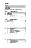
ix About this guide x Striker II Extreme / Striker II NSE specifications summary xii Chapter 1: Product introduction 1.1 Welcome 1-1 1.2 Package contents 1-1 1.3 Special features 1-2 1.3.1 Product highlights 1-2 1.3.2 ROG Intelligent Performance & Overclocking features... 1-4 1.3.3 ROG unique - Asus STRIKER II EXTREME | User Manual - Page 4
switch 3-2 Chapter 4: BIOS setup 4.1 Managing and updating your BIOS 4-1 4.1.1 ASUS Update utility 4-1 4.1.2 ASUS EZ Flash 2 utility 4-4 4.1.3 Updating the BIOS 4-5 4.1.4 Saving the current BIOS file 4-7 4.1.5 ASUS CrashFree BIOS utility 4-8 4.2 BIOS setup program 4-9 4.2.1 BIOS menu screen - Asus STRIKER II EXTREME | User Manual - Page 5
System Performance Settings 4-13 4.4 Main menu 4-20 4.4.1 System Time 4-20 4.4.2 System Date 4-20 4.4.3 Language 4-20 4.4.4 Legacy Diskette A 4-20 4.4.5 Primary IDE Master/Slave 4-21 4.4.6 SATA 1-6 4-23 4.4.7 HDD SMART Monitoring 4-24 4.4.8 Installed Memory 4-24 4.4.9 Usable Memory 4-24 - Asus STRIKER II EXTREME | User Manual - Page 6
35 5.4.2 NVIDIA® RAID configurations 5-36 5.4.4 JMicron® RAID Configuration 5-43 5.5 Creating a RAID driver disk 5-51 5.5.1 Creating a RAID driver disk without entering the OS.... 5-51 5.5.2 Creating a RAID/SATA driver disk in Windows 5-51 Chapter 6: NVIDIA® SLI™ technology support 6.1 Overview - Asus STRIKER II EXTREME | User Manual - Page 7
Contents 6.2 Graphics card setup 6-2 6.2.1 Installing three SLI-ready graphics cards 6-2 6.2.2 Installing two SLI-ready graphics cards 6-5 6.2.3 Installing the device drivers 6-6 6.2.4 Enabling the NVIDIA® SLI™ technology in Windows®..... 6-6 Appendix: CPU features A.1 Intel® EM64T A-1 A.2 - Asus STRIKER II EXTREME | User Manual - Page 8
energy and, if not installed and used in accordance with manufacturer's instructions, may cause harmful interference to radio communications. However, there is Class B limits for radio noise emissions from digital apparatus set out in the Radio Interference Regulations of the Canadian Department of - Asus STRIKER II EXTREME | User Manual - Page 9
supply is broken, do not try to fix it by yourself. Contact a qualified service technician or your retailer. Operation safety • Before installing the motherboard and adding devices on it, carefully read all the manuals that came with the package. • Before using the product, make sure all cables - Asus STRIKER II EXTREME | User Manual - Page 10
change system settings through the BIOS Setup menus. Detailed descriptions of the BIOS parameters are also provided. • Chapter 5: Software support This chapter describes the contents of the support DVD that comes with the motherboard package. • Chapter 6: NVIDIA® SLI™ technology support This chapter - Asus STRIKER II EXTREME | User Manual - Page 11
the following symbols used throughout this manual. DANGER/WARNING: Information to prevent injury to yourself when trying to complete a task. CAUTION: Information to prevent damage to the components when trying to complete a task. IMPORTANT: Instructions that you MUST follow to complete - Asus STRIKER II EXTREME | User Manual - Page 12
multi-core CPUs Compatible with Intel® 0��6�/�0�5�B�/�0�5�A��p�ro��c�e�s�s�o�rs� * Refer to www.asus.com for Intel CPU support list Striker II Extreme: NVIDIA® nForce® 790i Ultra SLI™ Striker II NSE: NVIDIA® nForce® 790i SLI™ 1600/1333/1066/800 MHz Dual-channel memory architecture supports NVIDIA - Asus STRIKER II EXTREME | User Manual - Page 13
II Extreme / Striker II NSE specifications summary IEEE 1394 USB ROG Exclusive Overclocking features ROG Special Features Back Panel I/O Ports 2 x IEEE 1394a ports (one at midboard; one at back panel) 10 x USB 2.0 ports (4 ports at midboard, 6 ports at back panel) Extreme Tweaker 2-Phase DDR3 - Asus STRIKER II EXTREME | User Manual - Page 14
Serial ATA cables Serial ATA power cables 2-port USB2.0 + IEEE 1394a module EL I/O shield Thermal sensor cables Cable ties User's manual The hottest DX10 game: Company of Heroes-Opposing Fronts Support DVD: Drivers ASUS PC Probe II ASUS Update ASUS AI Suite Futuremark® 3DMark® 06 Advanced Edition - Asus STRIKER II EXTREME | User Manual - Page 15
This chapter describes the motherboard features and the new technologies it supports. Chapter 1: 1Product introduction - Asus STRIKER II EXTREME | User Manual - Page 16
Chapter summary 1 1.1 Welcome 1-1 1.2 Package contents 1-1 1.3 Special features 1-2 ROG Striker II Extreme / Striker II NSE - Asus STRIKER II EXTREME | User Manual - Page 17
3-in-1 ASUS Q-Connector Kit Cable ties DIY Pedestal Application DVD/CD ROG motherboard support DVD The hottest game: Company of Heroes-Opposing Fronts Documentation User guide If any of the above items is damaged or missing, contact your retailer. ROG Striker II Extreme / Striker II NSE 1-1 - Asus STRIKER II EXTREME | User Manual - Page 18
. NVIDIA® nForce® 790i Ultra SLI / 790i SLI chipset The NVIDIA® nForce 790i Ultra SLI / 790i SLI chipset supports the NVIDIA® Scalable Link Interface (SLI™) technology that allows three graphics processing units (GPUs) in a single system. It's designed for enthusiast, extreme overclocking capability - Asus STRIKER II EXTREME | User Manual - Page 19
. The dual-channel DDR3 architecture doubles the bandwidth of your system memory to boost system performance. See page 2‑18 for details. PCIe 2.0 This motherboard supports the latest PCIe 2.0 multi-channel network games. See pages 2-30 for details. ROG Striker II Extreme / Striker II NSE 1-3 - Asus STRIKER II EXTREME | User Manual - Page 20
Phase DDR3, this motherboard allows users to reach higher memory frequencies and enjoy better performance. Compared with only one phase solutions, this motherboard ensures longer power component life spans and higher overclockability due to cooler temperatures and better efficiency. Extreme Tweaker - Asus STRIKER II EXTREME | User Manual - Page 21
overclocking failure, there is no need to open the system chassis to clear CMOS data. Simply reboot the system, and the BIOS automatically restores the CPU default settings for each parameter. Due to the chipset behavior, AC power off is required before using C.P.R. function. ROG Striker II Extreme - Asus STRIKER II EXTREME | User Manual - Page 22
II features unique audio innovations for gamers to spot enemies in 3D environment during game play. SupremeFX II recording. ASUS EPU The ASUS EPU utilizes can help you attain the best possible power efficiency and energy With an easy press during overclocking, this exclusive onboard switch allows - Asus STRIKER II EXTREME | User Manual - Page 23
entire system. See pages 2-16 and 2-17 for details. ASUS MyLogo 3 ASUS MyLogo 3 is a new feature present in the motherboard that allows you to personalize and add style to your system with customizable and animated boot logos. See page 4-40 for details. ROG Striker II Extreme / Striker II NSE 1-7 - Asus STRIKER II EXTREME | User Manual - Page 24
ways to install computer components, update the BIOS or back up your favorite settings. ASUS Q-Connector The ASUS Q-Connector allows you to connect or disconnect chassis front panel cables in one easy step with one complete module. This unique adapter eliminates the trouble of plugging in one cable - Asus STRIKER II EXTREME | User Manual - Page 25
This chapter lists the hardware setup procedures that you have to perform when installing system components. It includes description of the jumpers and connectors on the motherboard. Chapter 2: 2 Hardware information - Asus STRIKER II EXTREME | User Manual - Page 26
Before you proceed 2-1 2.2 Motherboard overview 2-5 2.3 Central Processing Unit (CPU 2-9 2.4 System memory 2-18 2.5 Expansion slots 2-22 2.6 Slide switch 2-26 2.7 Aduio card, EL I/O shield, and LCD Poster Installation.......... 2-27 2.8 Connectors 2-29 ROG Striker II Extreme / Striker II NSE - Asus STRIKER II EXTREME | User Manual - Page 27
precautions before you install motherboard components or change any motherboard settings. • Unplug the power BIOS. Refer to the illustration below for the location of the CPU LED and the table below for LED definition. CPU_CRAZY CPU_HIGH CPU_NORMAL STRIKER II EXTREME STRIKER II EXTREME/ STRIKER II - Asus STRIKER II EXTREME | User Manual - Page 28
DDR_NORMAL STRIKER II EXTREME/ STRIKER II NSE DDR LED Memory Voltage Normal (green) 1.50~1.90 High (yellow) 1.92~2.30 Crazy (red) 2.32~ 3. Northbridge/Southbridge LEDs The northbridge LED displays either the NB Core Voltage or the CPU VTT Voltage; you can select the voltage to display in BIOS - Asus STRIKER II EXTREME | User Manual - Page 29
the table below for LED definition. FREQUENCY STRIKER II EXTREME STRIKER II EXTREME/ STRIKER II NSE Frequency LED CPU FSB 200MHz 200-299 300-399 400-499 500-599 600~ (Default) (Overclocking) (Overclocking) (Overclocking) (Overclocking) 1 2 3 4 5 (Default) (Fast) CPU FSB 266MHz 266 - Asus STRIKER II EXTREME | User Manual - Page 30
not light up when there is no hard disk drive connected to the motherboard or when the hard disk drive does not function. STRIKER II EXTREME HD_LED STRIKER II EXTREME/ STRIKER II NSE Hard Disk LED 6. Power LED The motherboard comes with a power-on switch that lights up to indicate that the system - Asus STRIKER II EXTREME | User Manual - Page 31
. 2.2.2 Screw holes Place nine (9) screws into the holes indicated by circles to secure the motherboard to the chassis. DO NOT overtighten the screws! Doing so can damage the motherboard. Place this side towards the rear of the chassis STRIKER II EXTREME ROG Striker II Extreme / Striker II NSE 2-5 - Asus STRIKER II EXTREME | User Manual - Page 32
JMB363 NVIDIA® nForce® 790i(Ultra) SLI™ CHA_FAN2 SPDIF_OUT ROG PCIEX1_1 NB_CRAZY NB_HIGH NB_NORMAL PCIEX16_1 DDR_CRAZY DDR_HIGH DDR_NORMAL OPT_FAN1 OPT_TEMP1 SATA1 SATA2 88E1116 OPT_TEMP2 88E1116 PCIEX1_2 Lithium Cell CMOS Power OPT_FAN2 PCIEX16_3 STRIKER II EXTREME* PCI1 VIA - Asus STRIKER II EXTREME | User Manual - Page 33
Clear CMOS switch 15. Optical S/PDIF Out port 16. USB 2.0 ports 5 and 6 *These audio ports are on the Supreme FX II audio card. Page 2-18 2-24 2-24 2-24 Page 2-26 Page 2-29 2-29 2-29 2-29 2-30 2-30 2-30 2-30 2-30 2-30 2-30 2-30 2-31 2-31 2-31 2-31 ROG Striker II Extreme / Striker II NSE 2-7 - Asus STRIKER II EXTREME | User Manual - Page 34
4. USB connectors (10-1 pin USB78, USB910) 5. IEEE 1394a port connector (10-1 pin IE1394_2) 6. Thermal sensor cable connectors (2-pin connector (4-1 pin CHASSIS) 9. Digital audio connector (4-1 pin SPDIF_OUT, for ASUS HDMI VGA card) 10. ATX power connectors (24-pin EATXPWR, 8-pin - Asus STRIKER II EXTREME | User Manual - Page 35
(RMA) requests only if the motherboard comes with the cap on the LGA775 socket. • The product warranty does not cover damage to the socket contacts resulting from incorrect CPU installation/removal, or misplacement/loss/ incorrect removal of the PnP cap. ROG Striker II Extreme / Striker II NSE 2-9 - Asus STRIKER II EXTREME | User Manual - Page 36
2.3.1 Installing the CPU To install a CPU: 1. Locate the CPU socket on the motherboard. STRIKER II EXTREME STRIKER II EXTREME/ STRIKER II NSE CPU socket 775 Before installing the CPU, make sure that the cam box is facing towards you and the load lever is on your left. 2. Press the load - Asus STRIKER II EXTREME | User Manual - Page 37
. The motherboard supports Intel® LGA775 processors with the Intel® Enhanced Memory 64 Technology (EM64T), Enhanced Intel SpeedStep® Technology (EIST), and Hyper-Threading Technology. Refer to the Appendix for more information on these CPU features. ROG Striker II Extreme / Striker II NSE 2-11 - Asus STRIKER II EXTREME | User Manual - Page 38
applied Thermal Interface Material to the CPU heatsink or CPU before you install the heatsink and fan assembly. Make sure that you have installed the motherboard to the chassis before you install the CPU fan and heatsink assembly. To install the CPU heatsink and fan: 1. Place the heatsink on top of - Asus STRIKER II EXTREME | User Manual - Page 39
fan assembly in B place. A A A B B B A 3. Connect the CPU fan cable to the connector on the motherboard labeled CPU_FAN. CPU_FAN GND CPU FAN PWR CPU FAN IN CPU FAN PWM STRIKER II EXTREME STRIKER II EXTREME/ STRIKER II NSE CPU fan connector DO NOT forget to connect the CPU fan connector - Asus STRIKER II EXTREME | User Manual - Page 40
the CPU heatsink and fan To uninstall the CPU heatsink and fan: 1. Disconnect the CPU fan cable from the connector on the motherboard. 2. Rotate each fastener counterclockwise. 3. Pull up two fasteners at a time in a diagonal sequence to disengage the heatsink and fan assembly from B the - Asus STRIKER II EXTREME | User Manual - Page 41
end of the groove Refer to the documentation in the boxed or stand-alone CPU fan package for detailed information on CPU fan installation. ROG Striker II Extreme / Striker II NSE 2-15 - Asus STRIKER II EXTREME | User Manual - Page 42
optional fans when you are using a water cooler �to��o��b�t�a�i�n��b�e��t�te��r heat dissipation�. it snugly fits the heatsink, then on the motherboard. connect the fan cable. • Plug the optional fan cable in the CHA_FAN1/2 connector on the motherboard. • Make sure the optional fan is installed - Asus STRIKER II EXTREME | User Manual - Page 43
5. Follow Step 1 to 4 to install the other optional fan. 6. The photo shows that two fans are installed to the motherboard. Plug the optional fan cable in the PWR_FAN connector on the motherboard. ROG Striker II Extreme / Striker II NSE 2-17 - Asus STRIKER II EXTREME | User Manual - Page 44
of the DDR3 DIMM sockets: STRIKER II EXTREME DIMM_A1 DIMM_A2 DIMM_B1 DIMM_B2 STRIKER II EXTREME/ STRIKER II NSE 240-pin DDR3 DIMM sockets Channel Channel A Channel B Sockets DIMM_A1 and DIMM_A2 DIMM_B1 and DIMM_B2 The motherboard supports up to 1333MHz and provides more ratio setting items - Asus STRIKER II EXTREME | User Manual - Page 45
on memory limitations • Due to chipset limitation, this motherboard can only support up to 8 GB on the operating systems listed below. You may install a maximum of 2 GB DIMMs on each slot. 64-bit Windows® XP Professional x64 Edition Windows® Vista x64 Edition ROG Striker II Extreme / Striker II NSE - Asus STRIKER II EXTREME | User Manual - Page 46
Striker II Extreme / Striker II NSE Motherboard Qualified Vendors Lists (QVL) DDR3-1066MHz capability Size memory configuration. • C*: Supports four modules inserted into both the blue and white slots as two pairs of Dual-channel memory configuration. Visit the ASUS website for the latest DDR3 - Asus STRIKER II EXTREME | User Manual - Page 47
the motherboard and DDR3 DIMM notch clips outward to unlock the DIMM. 1 1 Support the DIMM lightly with your fingers when pressing the retaining clips. The DIMM might get damaged when it flips out with extra force. 2. Remove the DIMM from the socket. ROG Striker II Extreme / Striker II - Asus STRIKER II EXTREME | User Manual - Page 48
and damage motherboard components. BIOS settings, if any. See Chapter 4 for information on BIOS setup. 2. Assign an IRQ to the card. Refer to the tables on the next page. 3. Install the software drivers for the expansion card. When using PCI cards on shared slots, ensure that the drivers support - Asus STRIKER II EXTREME | User Manual - Page 49
10 NVIDIA nForce PCI system management 11 IRQ holder for PCI steering 12 PS/2 compatible mouse port 13 Numeric 2.0 controller 2 - - shared - - - - - SATA controller 1 - - - - - - shared - SATA controller 2 - - - - - - shared - ROG Striker II Extreme / Striker II NSE 2-23 - Asus STRIKER II EXTREME | User Manual - Page 50
of the slots. • Install the audio card prior to other compatible cards to the black PCIe x1 slot. • Install a PCIe x1 device to a PCIe x1 slot prior to a PCIe x16 slot. 2.5.6 PCI Express x16 slots This motherboard supports three SLI™-ready Express x16 graphics cards that comply with the PCI Express - Asus STRIKER II EXTREME | User Manual - Page 51
to the motherboard connector labeled CHA_FAN2 SLI™ mode, use the PCIe 2.0 slots (blue slots) for PCI Express x16 graphics cards to get better performance. • We recommend that you provide sufficient power when running NVIDIA® SLI™ mode. See page 2-37 for details. ROG Striker II Extreme / Striker II - Asus STRIKER II EXTREME | User Manual - Page 52
and enter BIOS setup to re-enter data. STRIKER II EXTREME CLRTC_SW Enable (Default) Disable STRIKER II EXTREME/ STRIKER II NSE Clear RTC RAM slide switch the BIOS can automatically reset CPU parameter settings to default values. If the system hangs due to overclocking of memory timing or - Asus STRIKER II EXTREME | User Manual - Page 53
the Audio card from the package. 2. Locate the audio slot on the motherboard. 3. Align the card connector with the slot and press firmly until the card sits on the slot completely. 4. The photo below shows the audio card installed on the motherboard. ROG Striker II Extreme / Striker II NSE 2-27 - Asus STRIKER II EXTREME | User Manual - Page 54
and install chassis by snaping it in place from it to the chassis. Make sure that the inside. motherboard external ports fit the I/O openings. 3. Locate the EL_CON connector 4. Thread the LCD Poster cable and connect the shield cable to the through the back I/O shield opening connector - Asus STRIKER II EXTREME | User Manual - Page 55
ON/OFF 100 Mbps connection 1 Gbps connection 64-bit OS LAN port LED indications Activity/Link OFF YELLOW* YELLOW* YELLOW* * Blinking Speed LED OFF OFF ORANGE GREEN Description Soft-off Mode During Power ON/OFF 100 Mbps connection 1 Gbps connection ROG Striker II Extreme / Striker II NSE 2-29 - Asus STRIKER II EXTREME | User Manual - Page 56
USB 2.0 devices. 12. External SATA port 1/2. These ports connect to external Serial ATA hard disk drives. To configure a RAID0, RAID1, RAID 0+1, RAID 5 or JBOD set, connect external Serial ATA hard disk drives to the External SATA port 1/2. The external SATA port supports external Serial ATA 3.0 Gb - Asus STRIKER II EXTREME | User Manual - Page 57
controller in the BIOS to [AHCI]. See section 4.5.3 Onboard Device Configuration for details. • Before creating a RAID set, refer to 5.4.4 JMicron® RAID Configuration or the manual bundled in the motherboard support DVD. • DO NOT insert different cables to the external SATA ports. • DO NOT unplug - Asus STRIKER II EXTREME | User Manual - Page 58
IDE cable for Ultra DMA 133/100/66 IDE devices. If any device jumper is set as "Cable-Select," make sure all other device jumpers have the same setting. PRI_IDE NOTE:Orient the red markings on the IDE ribbon cable to PIN 1. STRIKER II EXTREME PIN1 STRIKER II EXTREME/ STRIKER II NSE IDE connector - Asus STRIKER II EXTREME | User Manual - Page 59
. Use two to four Serial ATA hard disk drives for each RAID 0 or RAID 1 set. • Before creating a RAID set, refer to 5.4.2 NVIDIA® RAID configurations or the manual bundled in the motherboard support DVD. STRIKER II EXTREME SATA5 GND RSATA_TXP5 RSATA_TXN5 GND RSATA_RXP5 RSATA_RXN5 GND SATA6 GND - Asus STRIKER II EXTREME | User Manual - Page 60
1 USB+5V USB_P9USB_P9+ GND USB+5V USB_P7USB_P7+ GND STRIKER II EXTREME/ STRIKER II NSE USB2.0 connectors Never connect a 1394 cable to the USB connectors. Doing so will damage the motherboard! You can connect the USB cable to ASUS Q-Connector (USB, blue) first, and then install the Q-Connector - Asus STRIKER II EXTREME | User Manual - Page 61
. TPA2GND TPB2+12V GND STRIKER II EXTREME IE1394_2 PIN 1 TPA2+ GND TPB2+ +12V STRIKER II EXTREME/ STRIKER II NSE IEEE 1394 connector Never connect a USB cable to the IEEE 1394a connector. Doing so will damage the motherboard! You can connect the 1394 cable to ASUS Q-Connector (1394, red) first - Asus STRIKER II EXTREME | User Manual - Page 62
12V Rotation CHA_FAN3 STRIKER II EXTREME/ STRIKER II NSE Fan connectors • Only the CPU_FAN, CHA_FAN1-3, and OPT_FAN1-3 connectors support the ASUS Q-Fan Plus feature. • If you install multiple VGA cards, we recommend that you plug the chassis fan cable to the motherboard connector labled CHA_FAN2 - Asus STRIKER II EXTREME | User Manual - Page 63
Digital Interface (S/PDIF) port(s). If you are using an ASUS HDMI-equipped graphics card, connect the HDMI card to this connector with a S/PDIF Out cable. +5V SPDIFOUT GND STRIKER II EXTREME SPDIF_OUT STRIKER II EXTREME/ STRIKER II NSE Digital audio connector The ASUS HDMI-equipped graphics card - Asus STRIKER II EXTREME | User Manual - Page 64
PIN 1 STRIKER II EXTREME/ STRIKER II NSE ATX support.asus .com/PowerSupplyCalculator/PSCalculator. aspx?SLanguage=en-us for details. • If you want to use two high-end PCI Express x16 cards, use a PSU with 500W to 600W power or above to ensure the system stability. • If you want to use 3-Way SLI - Asus STRIKER II EXTREME | User Manual - Page 65
KFD 2.93G Memory DDR3-1333*2 VGA PCIEX16-ASUS EN8800GT-512MX16-0004*1 SATA-HDD 4 SATA-HDD eSATA-HDD IDE-CDROM IDE-HDD USB Total PSU Voltage (V) 4 1 1 0 4 Po_max(w) Current (A) 10.45 10.45 10 Power (W) 41.8 10.45 10 12.68 2.5 0 10 318.2982 ROG Striker II Extreme / Striker II - Asus STRIKER II EXTREME | User Manual - Page 66
Light Loading CPU Memory VGA SATA-HDD eSATA-HDD IDE-CDROM IDE-HDD USB Conroe 3.0+EM64T DDR3-800 1 GB*2 PCIEX16-ASUS EN8600GT-256MX16-0004*1 2 1 1 0 4 +12V_8Pin +12V_24pin + system is on. STRIKER II EXTREME STRIKER II EXTREME/ STRIKER II NSE ROG connector 2-40 Chapter 2: Hardware information - Asus STRIKER II EXTREME | User Manual - Page 67
the BIOS settings. Pressing the power switch for more than four seconds while the system is ON turns the system OFF. • Reset button (2-pin RESET) This 2-pin connector is for the chassis-mounted reset button for system reboot without turning off the system power. ROG Striker II Extreme / Striker II - Asus STRIKER II EXTREME | User Manual - Page 68
a few steps. Refer to the instructions below to install the ASUS QConnector. 1. Connect the front panel cables to the ASUS Q-Connector. Refer to the labels 2. Install the ASUS Q-Connector to the system panel connector, making sure the orientation matches the labels on the motherboard. 3. The front - Asus STRIKER II EXTREME | User Manual - Page 69
bare or open-case system. This is ideal for overclockers and gamers who continually change settings to enhance system performance. 1. Power-on switch Press the power-on switch to wake/power up the system. STRIKER II EXTREME STRIKER II EXTREME/ STRIKER II NSE Power on switch 2. Reset switch Press the - Asus STRIKER II EXTREME | User Manual - Page 70
accessory Install your watercooling system to the motherboard using the bundled accessories to obtain the best thermal solution. Package contents 3/8" ID and fit the tube into the clamp. 2. Connect the tube to the waterblock and tighten the screw of the clamp using a screwdriver. 3. Repeat Step - Asus STRIKER II EXTREME | User Manual - Page 71
the assembled tube to the waterblock and tighten the screw of the clamp using a screwdriver. 6. Repeat Step 1 to 5 for another tube. Make sure that both tubes are well connected to prevent leak, and then fill the coolant into the reservoir. 5 6 ROG Striker II Extreme / Striker II NSE 2-45 - Asus STRIKER II EXTREME | User Manual - Page 72
2.8.5 Installing the DIY Pedestal 1. Take out the DIY Pedestal from the motherboard package. 2. Arrange and stick the DIY Pedestal to the back of your motherboard. 3. Place the motherboard with the DIY Pedestal as desired to get more efficient heat dissipation. • The tape on the rubber studs is for - Asus STRIKER II EXTREME | User Manual - Page 73
Chapter 3: Powerin3g up This chapter describes the power up sequence, the vocal POST messages, and ways of shutting down the system. - Asus STRIKER II EXTREME | User Manual - Page 74
Chapter summary 3 3.1 Starting up for the first time 3-1 3.2 Turning off the computer 3-2 ROG Striker II Extreme / Striker II NSE - Asus STRIKER II EXTREME | User Manual - Page 75
you turned on the power, the system may have failed a power-on test. Check the jumper settings and connections or call your retailer for assistance. 7. At power on, hold down the key to enter the BIOS Setup. Follow the instructions in Chapter 4. ROG Striker II Extreme / Striker II NSE 3-1 - Asus STRIKER II EXTREME | User Manual - Page 76
is ON, pressing the power switch for less than four seconds puts the system to sleep mode or to soft-off mode, depending on the BIOS setting. Pressing the power switch for more than four seconds lets the system enter the soft-off mode regardless of the - Asus STRIKER II EXTREME | User Manual - Page 77
This chapter tells how to change the system settings through the BIOS Setup menus. Detailed descriptions of the BIOS parameters are also provided. Chapter 4: 4 BIOS setup - Asus STRIKER II EXTREME | User Manual - Page 78
Chapter summary 4 4.1 Managing and updating your BIOS 4-1 4.2 BIOS setup program 4-9 4.3 Extreme Tweaker menu 4-13 4.4 Main menu 4-20 4.5 Advanced menu 4-25 4.6 Power menu 4-31 4.7 Boot menu 4-37 4.8 Tools menu 4-42 4.9 Exit menu 4-45 ROG Striker II Extreme / Striker II NSE - Asus STRIKER II EXTREME | User Manual - Page 79
Service Provider (ISP). Installing ASUS Update To install ASUS Update: 1. Place the support DVD in the optical drive. The Drivers menu appears. 2. Click the Utilities tab, then click Install ASUS Update VX.XX.XX. 3. The ASUS Update utility is copied to your system. ROG Striker II Extreme / Striker - Asus STRIKER II EXTREME | User Manual - Page 80
update the BIOS using this utility. Updating the BIOS through the Internet To update the BIOS through the Internet: 1. Launch the ASUS Update utility from the Windows® desktop by clicking Start > Programs > ASUS > ASUSUpdate > ASUSUpdate. The ASUS Update main window appears. 2. Select Update BIOS - Asus STRIKER II EXTREME | User Manual - Page 81
. The ASUS Update main window appears. 2. Select Update BIOS from a file option from the drop‑down menu, then click Next. 3. Locate the BIOS file from the Open window, then click Open. 4. Follow the screen instructions to complete the update process. StrikerII StrikerII ROG Striker II Extreme - Asus STRIKER II EXTREME | User Manual - Page 82
flash disk that contains the BIOS file to the USB port. Press + during POST to display the following. ASUSTek EZ Flash 2 BIOS ROM Utility B327 FLASH TYPE: Winbond W39V080A 8Mb LPC Current ROM BOARD: STRIKER II EXTREME VER: 0106 DATE: 01/18/2008 Update ROM BOARD: Unknown VER: Unknown - Asus STRIKER II EXTREME | User Manual - Page 83
Basic Input/Output System (BIOS) can be updated using the AwardBIOS Flash Utility. Follow these instructions to update the BIOS using this utility. 1. Download the latest BIOS file from the ASUS web site. Rename the Message: Do You Want To Save Bios (Y/N) ROG Striker II Extreme / Striker II NSE 4-5 - Asus STRIKER II EXTREME | User Manual - Page 84
the BIOS file. AwardBIOS Flash Utility for ASUS V1.18 (C) Phoenix Technologies Ltd. All Rights Reserved For C55XEMCP55PXE-StrikerII-00 DATE:10/30/2007 Flash Type - PMC Pm49FL004T LPC/FWH File Name to Program: StrikerII.bin Programming Flash Memory - OFE00 OK Write OK No Update Write - Asus STRIKER II EXTREME | User Manual - Page 85
Utility for ASUS V1.18 (C) Phoenix Technologies Ltd. All Rights Reserved For C55XEMCP55PXE-StrikerII-00 DATE:10/30/2007 Flash Type - PMC Pm49FL004T LPC/FWH File Name to Program: StrikerII.bin Now Backup System BIOS to File! Message: Please Wait! ROG Striker II Extreme / Striker II NSE 4-7 - Asus STRIKER II EXTREME | User Manual - Page 86
file for this motherboard. If the BIOS file that you downloaded from the ASUS website has a different filename (e.g. Striker.BIN), rename it to StrikerII.BIN. The BIOS update process continues when the �S�t�r�ik�e��r�II�.�B�I�N��i�s��f�o�u�n��d�. Bad BIOS checksum. Starting BIOS recovery... Checking - Asus STRIKER II EXTREME | User Manual - Page 87
section 4.9 Exit Menu. • The BIOS setup screens shown in this section are for reference purposes only, and may not exactly match what you see on your screen. • Visit the ASUS website (www.asus.com) to download the latest BIOS file for this motherboard. ROG Striker II Extreme / Striker II NSE 4-9 - Asus STRIKER II EXTREME | User Manual - Page 88
Primary IDE Master Primary IDE Slave SATA 1 SATA 2 SATA 3 SATA 4 SATA 5 SATA 6 HDD SMART Monitoring Installed Memory Usable Memory System Information [None] [None] Extreme Tweaker For changing the overclocking settings Advanced For changing the advanced system settings - Asus STRIKER II EXTREME | User Manual - Page 89
+ (plus) Function Displays the General Help screen Loads setup default values Exits the BIOS setup or returns to the main menu from a sub‑menu Selects the menu item to the left or display a list of options. Refer to "4.2.7 Pop-up window." ROG Striker II Extreme / Striker II NSE 4-11 - Asus STRIKER II EXTREME | User Manual - Page 90
. Phoenix-AwardBIOS CMOS Setup Utility Extreme Tweaker Main Advanced Power Boot Tools SATA 1 720K , 3.[5Noinne.] ..... [ ] SATA 2 1.44M, 3.[5Noinne.] ..... [ ] SATA 3 [None] SATA 4 [None] SATA 5 [None] SATA 6 [None] HDD SMART Monitoring [Disabled] Installed Memory BIOS setup - Asus STRIKER II EXTREME | User Manual - Page 91
to [Manual] after selecting a CPU level. Configuration options: [Auto] [E6300] [E6400] [E6550] [E6600] [E6700] [X6800] [E6850] [E8200] [E8400] [E8500] [E6850] [Q9450] [Q9550] [QX9650] [QX9770] [Crazy] The configuration options may vary depending on your CPU type. ROG Striker II Extreme / Striker II - Asus STRIKER II EXTREME | User Manual - Page 92
Overclock 5%] [Overclock 10%] [Overclock 15%] [Overclock 20%] The following items become configurable when you set AI Overclock Tuner to [Manual]. CPU Multiplier [8 X] Use the and keys or the numeric keypad to enter the desired value. The values range from 6 to 50. FSB - Memory 4: BIOS setup - Asus STRIKER II EXTREME | User Manual - Page 93
set the PCIEX16_3 overclocking frequency. Use the and keys to adjust the frequency. The values range from 100 to 200. Memory Timing Setting Phoenix-AwardBIOS CMOS Setup Utility Extreme Tweaker Memory Timing Setting : [Auto] [5] [6]-[18] ROG Striker II Extreme / Striker II NSE 4-15 - Asus STRIKER II EXTREME | User Manual - Page 94
CPU LED color, both of which indicate voltage condition. When you set the CPU LED Selection item to [CPU Volt], the onboard CPU LED displays to the CPU documentation before setting the CPU voltage. Setting a high voltage may damage the CPU permanently, and setting a low voltage may make - Asus STRIKER II EXTREME | User Manual - Page 95
] [1.55V] [1.60V] [1.65V]~[1.80V] [1.85V] 1.5V SB Voltage [Auto] Allows you to select the southbridge 1.5V voltage. Configuration options: [Auto] [1.50V] [1.60V] [1.70V] [1.80V] ROG Striker II Extreme / Striker II NSE 4-17 - Asus STRIKER II EXTREME | User Manual - Page 96
124mV] [-126mV] DDR3 CHA/B 1/2 Ref Voltage [Auto] Allows you to manually set the memory voltage, or you can set to [Auto] Configuration Extreme Tweaker Phoenix-AwardBIOS CMOS Setup Utility Overclocking Select Menu CPU Type CPU Speed Cache RAM(L2 F10: Save and Exit 4-18 Chapter 4: BIOS setup - Asus STRIKER II EXTREME | User Manual - Page 97
MaxVal [Disabled] Setting this item to [Enabled] allows legacy operating systems to boot even without support for CPUs SATA Spread Spectrum [Disabled] Configuration options: [Disabled] [Enabled] LDT Spread Spectrum [Auto] Configuration options: [Auto] [Disabled] ROG Striker II Extreme / Striker II - Asus STRIKER II EXTREME | User Manual - Page 98
Extreme Tweaker Main Advanced Power Boot System Time System Date Language Legacy Diskette A: 15 : 30 : 36 Thu, Oct 30 2007 [English] [1.44M, 3.5 in.] Primary IDE Master Primary IDE Slave SATA 1 SATA 2 SATA 3 SATA 4 SATA 5 SATA 6 HDD SMART Monitoring Installed Memory - Asus STRIKER II EXTREME | User Manual - Page 99
] [Auto] 0 MB Item Specific Help Set a PIO mode for the IDE device. BIOS may detect incorrect parameters. Select [Manual] to manually enter the IDE hard disk drive parameters. If no drive is installed select [None]. Configuration options: [None] [Auto] [Manual] ROG Striker II Extreme / Striker II - Asus STRIKER II EXTREME | User Manual - Page 100
hard disk drive. Select [CHS] for this item if you set the IDE Primary Master/Slave to [Manual]. Configuration options: [CHS] [LBA] [Large] [Auto] item is not configurable. After entering the IDE hard disk drive information into BIOS, use a disk utility, such as FDISK, to partition and format new - Asus STRIKER II EXTREME | User Manual - Page 101
BIOS automatically detects the presence of Serial ATA devices. There is a separate sub-menu for each SATA device. Select a device item then press to display the SATA device information. Phoenix-AwardBIOS CMOS Setup Utility Main SATA settings may Striker II Extreme / Striker II NSE 4-23 - Asus STRIKER II EXTREME | User Manual - Page 102
can write or read data from the hard disk. Make sure to set the partition of the Primary IDE hard disk drives to active. memory. 4.4.9 Usable Memory [xxx MB] Shows the size of usable memory. 4.4.10 System Information This menu gives you an overview of the general system specifications. The BIOS - Asus STRIKER II EXTREME | User Manual - Page 103
menu items allow you to change the settings for the CPU and other system devices. Phoenix-AwardBIOS CMOS Setup Utility Extreme Tweaker �M�a��i��n� Advanced Power AI NET2 PCIPnP the Power-On Self‑Test (POST). Configuration options: [Disabled] [Enabled] ROG Striker II Extreme / Striker II NSE 4-25 - Asus STRIKER II EXTREME | User Manual - Page 104
you need the BIOS to configure non-boot devices. Plug & Play O/S [No] When set to [No], the BIOS configures all the devices in the system. When set to [Yes] and Menu HD Audio Front Panel Support Type Onboard 1st nVidia LAN Onboard 2nd nVidia LAN JMicron RAID controller Onboard LAN Boot ROM - Asus STRIKER II EXTREME | User Manual - Page 105
to enable or disable support for USB devices on legacy operating systems (OS). Configuration options: [Disabled] [Enabled] USB 2.0 Controller [Enabled] Allows you to enable or disable the USB 2.0 controller. Configuration options: [Disabled] [Enabled] ROG Striker II Extreme / Striker II NSE 4-27 - Asus STRIKER II EXTREME | User Manual - Page 106
Serial ATA settings. Select an item then press to edit. Phoenix-AwardBIOS CMOS Setup Utility Advanced Serial-ATA Configuration Select Menu Serial-ATA Controller RAID Enabled x SATA 1 Primary RAID x SATA 1 Secondary RAID x SATA 2 Primary RAID x SATA 2 Secondary RAID x SATA - Asus STRIKER II EXTREME | User Manual - Page 107
RAID controller. When set to [Enabled], the succeeding items become user-configurable. Configuration options: [Disabled] [Enabled] SATA1/2/3 Primary/Secondary RAID [Disabled] Enables or disables the RAID function of the SATA [Current Time] [User String] ROG Striker II Extreme / Striker II NSE 4-29 - Asus STRIKER II EXTREME | User Manual - Page 108
following item becomes configurable when you set LCD Poster Mode to [User Allows you to turn on/off the onboard Voltiminder LED. Configuration options: [ON] [OFF] CPU Overclocking LED [ON] Allows you to turn on/off the CPU LED. Configuration options: [ON] [ ] [VTT Volt] 4-30 Chapter 4: BIOS setup - Asus STRIKER II EXTREME | User Manual - Page 109
the Advanced Configuration and Power Interface (ACPI) support in the Application-Specific Integrated Circuit (ASIC). When set to Enabled, the ACPI APIC table pointer is included in the RSDT pointer list. Configuration options: [Disabled] [Enabled] ROG Striker II Extreme / Striker II NSE 4-31 - Asus STRIKER II EXTREME | User Manual - Page 110
or disable the support of USB keyboard set the date of alarm, highlight this item and press to display the Date of Month Alarm pop-up menu. Key-in a value within the specified range then press . Value '0' means everyday. Configuration options: [Min=0] [Max=31] 4-32 Chapter 4: BIOS - Asus STRIKER II EXTREME | User Manual - Page 111
Min=0, Max=59), then press . HPET Support [Enabled] Configuration options: [Disabled] [Enabled] Power Power On by PS/2 keyboard function or set specific keys on the PS/2 keyboard to values automatically detected by the BIOS. It also allows you to Striker II Extreme / Striker II NSE 4-33 - Asus STRIKER II EXTREME | User Manual - Page 112
set. F1:Help ESC: Exit ↑↓ : Select Item →←: Select Menu -/+: Change Value Enter: Select SubMenu F5: Setup Defaults F10: Save and Exit Vcore, CPU PLL, CPU VTT, Memory, NB Core , SB Core, DDR3 Item Specific Help Set NB Over-Heat the CPU, motherboard, northbridge, the set temperature to protect it - Asus STRIKER II EXTREME | User Manual - Page 113
[90] Allows you to set the temperature over which the system automatically shuts down when any of the thermal sensor cables connected to the motherboard detects device overheat to protect the Enter: Select SubMenu F5: Setup Defaults F10: Save and Exit ROG Striker II Extreme / Striker II NSE 4-35 - Asus STRIKER II EXTREME | User Manual - Page 114
OPT Fan1/2/3 and to adjust the fan speed. These items become configurable when the OPT FAN1/2/3 Control items are set to [Q-FAN Mode]. Configuration options: [10ºC/50ºF] [15ºC/59ºF] [20ºC/68ºF] [25ºC/77ºF] [30ºC/ to the OPT_TEMP1/2/3 connectors to enable this function. 4-36 Chapter 4: BIOS setup - Asus STRIKER II EXTREME | User Manual - Page 115
function, which gives off a warning when the CPU fan speed is too low. If you set this item to [Disabled], the system will not warn you even if no fan is installed in the system. Configuration options: [Removable] [Hard Disk] [CDROM] [Disabled] ROG Striker II Extreme / Striker II NSE 4-37 - Asus STRIKER II EXTREME | User Manual - Page 116
Utility Extreme Tweaker Advanced Power Boot Tools Hard Disk Drives Exit Select Menu 1. SATA 1: Press to exit this menu. 1. SATA 1: XXXXXXXXX Allows you to assign hard disk drives attached to Main Extreme Tweaker Advanced CDROM Drives Power Boot Tools Exit Select Menu 1. SATA 2: - Asus STRIKER II EXTREME | User Manual - Page 117
Delay (Msec) become configurable when the Typematic Rate Setting is enabled. Typematic Rate (Chars/Sec) [6] Allows you to select the rate at which a character repeats when you hold a key. Configuration options: [6] [8] [10] [12] [15] [20] [24] [30] ROG Striker II Extreme / Striker II NSE 4-39 - Asus STRIKER II EXTREME | User Manual - Page 118
DRAM > 64MB [Non-OS2] Set this item to OS2 only when you are running on an OS/2 operating system with an installed RAM of greater than 64 MB. Configuration set to [Enabled] if you want to use the ASUS MyLogo3™ feature. BIOS Wallpaper [00%] Allows you to select the transparency of the BIOS wallpaper - Asus STRIKER II EXTREME | User Manual - Page 119
you to enter the password before entering the BIOS setup or the system. Select [Setup] to require the password before entering the BIOS Setup. Select [System] to require the password before entering the system. Configuration options: [Setup] [System] ROG Striker II Extreme / Striker II NSE 4-41 - Asus STRIKER II EXTREME | User Manual - Page 120
Advanced Power Boot Tools Exit ASUS BIOS Profile Select Menu Load BIOS Profile Save BIOS Profile Item Specific Help Press [Enter] to select Load BIOS Profile Phoenix-AwardBIOS CMOS Setup Utility Main Extreme Tweaker Advanced Power Boot Tools Exit Load BIOS Profile Select Menu Load from - Asus STRIKER II EXTREME | User Manual - Page 121
update the BIOS file coming from the same memory/CPU configuration and BIOS version. • Only the "xxx.CMO" file can be loaded. Save BIOS Profile Main Phoenix-AwardBIOS CMOS Setup Utility Extreme Tweaker Advanced Power Boot Tools Save BIOS finishes. ROG Striker II Extreme / Striker II NSE 4-43 - Asus STRIKER II EXTREME | User Manual - Page 122
: STRIKER II EXTREME VER: 0106 DATE: 01/18/2008 Update CMOS BOARD: Unknown VER: Unknown DATE: Unknown PATH: A:\ A: CMOS backup is done! Press any key to Exit. Note [Enter] Select [Tab] Switch [S] Save [ESC]: Exit [Up/Down/Home/End] Move The BIOS file will be saved as "xxx.CMO". 4.8.3 ASUS - Asus STRIKER II EXTREME | User Manual - Page 123
, the BIOS asks for RAM. Discard Changes This option allows you to discard the selections you made and restore the previously saved values. After selecting this option, a confirmation appears. Select YES to discard any changes and load the previously saved values. ROG Striker II Extreme / Striker II - Asus STRIKER II EXTREME | User Manual - Page 124
4-46 Chapter 4: BIOS setup - Asus STRIKER II EXTREME | User Manual - Page 125
This chapter describes the contents of the support DVD that comes with the motherboard package. Chapter 5: 5 Software support - Asus STRIKER II EXTREME | User Manual - Page 126
Chapter summary 5 5.1 Installing an operating system 5-1 5.2 Support DVD information 5-1 5.3 Software information 5-9 5.4 RAID configurations 5-35 5.5 Creating a RAID driver disk 5-51 ROG Striker II Extreme / Striker II NSE - Asus STRIKER II EXTREME | User Manual - Page 127
to display support DVD/motherboard information Click an item to install If Autorun is NOT enabled in your computer, browse the contents of the support DVD to locate the file ASSETUP.EXE from the BIN folder. Double-click the ASSETUP.EXE to run the DVD. ROG Striker II Extreme / Striker II NSE 5-1 - Asus STRIKER II EXTREME | User Manual - Page 128
Installs the NVIDIA® chipset drivers for the NVIDIA® nForce® 790i (Ultra) SLI™ chipset. JMicron JMB36X Controller Driver Installs JMicron® JMB363 controller driver. ASUS EPU Driver + AI Gear 3 Utility Installs the ASUS EPU Driver + AI Gear 3 Utility. Install the ASUS EPU Driver + AI Gear 3 Utility - Asus STRIKER II EXTREME | User Manual - Page 129
through the Installation Wizard. ASUS PC Probe II This smart utility monitors the fan speed, CPU temperature, and system voltages, and alerts you of any detected problems. This utility helps you keep your computer in healthy operating condition. ROG Striker II Extreme / Striker II NSE 5-3 - Asus STRIKER II EXTREME | User Manual - Page 130
ASUS Update The ASUS Update utility allows you to update the motherboard BIOS in Windows® environment. This utility requires an Internet connection either through a network or an Internet Service Provider (ISP). ASUS AI Suite Installs the ASUS AI Suite. Adobe Acrobat Reader V7.0 Installs the Adobe® - Asus STRIKER II EXTREME | User Manual - Page 131
® nForce® 790i (Ultra) SLI™ or JMicron® JMB363 SATA RAID driver disk. NVIDIA 32/64 bit XP/Vista SATA RAID Driver Allows you to create a NVIDIA® 32/64 bit XP/Vista™ SATA RAID driver disk. JMicron JMB36X 32/64 bit SATA/RAID Driver Allows you to create a JMicron® JMB363 32/64 bit SATA/RAID driver disk - Asus STRIKER II EXTREME | User Manual - Page 132
® Acrobat® Reader from the Utilities menu before opening a user manual file. 5.2.6 Video menu Click the Video tab to display a list of video clips. Click the Extreme OC Clip item to watch how an overclocking guru breaks 3DMark world record with an ROG motherboard. 5-6 Chapter 5: Software support - Asus STRIKER II EXTREME | User Manual - Page 133
icons on the top right corner of the screen give additional information on the motherboard and the contents of the support DVD. Click an icon to display the specified information. Motherboard Info Displays the general specifications of the motherboard. ROG Striker II Extreme / Striker II NSE 5-7 - Asus STRIKER II EXTREME | User Manual - Page 134
Browse this DVD Displays the support DVD contents in graphical format. Technical support form Displays the ASUS Technical Support Request Form that you have to fill out when requesting technical support. Filelist Displays the contents of the support DVD and a brief description of each in text - Asus STRIKER II EXTREME | User Manual - Page 135
Select Update BIOS from a file from the drop down menu, then click Next. 5. When prompted, locate the new BIOS file, then click Next. The ASUS MyLogo window appears. 6. From the left window pane, select the folder that contains the image you intend to use as your boot logo. ROG Striker II Extreme - Asus STRIKER II EXTREME | User Manual - Page 136
the boot image to your desired size by selecting a value on the Ratio box. 9. When the screen returns to the ASUS Update utility, flash the original BIOS to load the new boot logo. 10. After flashing the BIOS, restart the computer to display the new boot logo during POST. 5-10 Chapter 5: Software - Asus STRIKER II EXTREME | User Manual - Page 137
Tester™ main window is disabled if no problem is detected on the LAN cable(s) connected to the LAN port(s). • If you want the system to check the status of the LAN cable before entering the OS, enable the item Post Check LAN Cable in the BIOS Setup. ROG Striker II Extreme / Striker II NSE 5-11 - Asus STRIKER II EXTREME | User Manual - Page 138
, 3D sound positioning, and advanced voice-input technologies. Follow the installation wizard to install the ADI AD1988 Audio Driver from the support DVD that comes with the motherboard package to activate the SoundMAX® audio utility. You must use 4-channel, 6-channel or 8-channel speakers for this - Asus STRIKER II EXTREME | User Manual - Page 139
the vocal clarity added for use with stereo speakers or headphones. SoundMAX BlackHawk (AI Audio2) is available only under the Windows® Vista™ operating system. ROG Striker II Extreme / Striker II NSE 5-13 - Asus STRIKER II EXTREME | User Manual - Page 140
or adjust the center channel volume. Press the Test Speakers button to perform speaker test. Port settings Click this port settings tab to display the rear panel ports configuration for the speakers or rear panel digital port configuration for the SPDIF interface. 5-14 Chapter 5: Software support - Asus STRIKER II EXTREME | User Manual - Page 141
SPDIF interface. Port settings Click the tab to display the rear panel ports for Microphone or Line In. ANDREA settings Allows you Settings Click for the further configurations. Equalizer Allows you to configure and customize all the DSP presets frequencies. ROG Striker II Extreme / Striker II - Asus STRIKER II EXTREME | User Manual - Page 142
Speakers Allows you to adjust the Speaker Trim and Speaker Delay. Bass Allows you to do the Bass management. Preferences Displays the preference options for this utility, version information, AudioESP, etc. 5-16 Chapter 5: Software support - Asus STRIKER II EXTREME | User Manual - Page 143
to display the SoundMAX® Control Panel. Audio Setup Wizard By clicking the icon from the SoundMAX® control panel, you can easily configure your audio settings. Simply follow the succeeding screen instructions and begin enjoying High Definition Audio. ROG Striker II Extreme / Striker II NSE 5-17 - Asus STRIKER II EXTREME | User Manual - Page 144
Jack configuration This screen helps you configure your computer's audio ports, depending on the audio devices you have installed. Adjust speaker volume This screen helps you adjust speaker -written text to allow the AudioWizard to adjust the volume as you speak. 5-18 Chapter 5: Software support - Asus STRIKER II EXTREME | User Manual - Page 145
devices, enable/ disable the AudioESP™ feature, and enable/disable digital output. Listening Environment options Click the Listening Environment tab to set up your speaker, acoustic environment, and enable/disable the Virtual Theater Surround function. ROG Striker II Extreme / Striker II NSE 5-19 - Asus STRIKER II EXTREME | User Manual - Page 146
Microphone options Click the Microphone tab allows you to optimize your microphone input settings. 5-20 Chapter 5: Software support - Asus STRIKER II EXTREME | User Manual - Page 147
contents of the support DVD to locate the setup.exe file from the ASUS PC Probe II folder. Double-click the setup.exe file to start installation. 2. Click the Utilities tab, then click ASUS PC Probe II. 3. Follow the screen instructions to complete installation. Launching PC Probe II You can launch - Asus STRIKER II EXTREME | User Manual - Page 148
the hard disk drive, memory, CPU usage window Shows/Hides the Preference section Minimizes the application Closes the application Sensor alert When a system sensor detects a problem, the main window right the box before each preference to activate or deactivate. 5-22 Chapter 5: Software support - Asus STRIKER II EXTREME | User Manual - Page 149
values using the Config window. You cannot adjust the sensor threshold values in a small monitoring panel. Click to increase value Click to decrease value ROG Striker II Extreme / Striker II NSE 5-23 - Asus STRIKER II EXTREME | User Manual - Page 150
Interface) browser. This browser displays various desktop and system information. Click the plus sign (+) before DMI Information to display the available information. 5-24 Chapter 5: Software support - Asus STRIKER II EXTREME | User Manual - Page 151
Usage The Usage browser displays real-time information on the CPU, hard disk drive space, and memory usage. Click to display the Usage browser. CPU usage The CPU tab displays realtime CPU usage window represents the used (blue) and the available HDD ROG Striker II Extreme / Striker II NSE 5-25 - Asus STRIKER II EXTREME | User Manual - Page 152
tab shows both used and available physical memory. The pie chart at the bottom of the window represents the used (blue) and the available Configuring PC Probe II Click to view and adjust the sensor Loads your saved configuration Saves your configuration 5-26 Chapter 5: Software support - Asus STRIKER II EXTREME | User Manual - Page 153
support DVD to the optical drive. The Drivers installation tab appears if your computer has an enabled Autorun feature. 2. Click the Utilities tab, then click AI Suite. 3. Follow the screen instructions AI Booster ROG Striker II Extreme / Striker II NSE Press to launch AI Nap Press to launch CPU Level - Asus STRIKER II EXTREME | User Manual - Page 154
Other feature buttons Click on right corner of the main window to open the monitor window. Displays the CPU/ system temperature, CPU/memory/PCIE voltage, and CPU/ chassis fan speed Displays the FSB/CPU frequency Click on right corner of the expanded window to switch the temperature from - Asus STRIKER II EXTREME | User Manual - Page 155
computing needs. After installing ASUS AI Suite from the bundled support DVD, you can launch ASUS AI Gear 3+ by ASUS EPUfeatured motherboard saved. Auto Mode Turbo Mode High Performance Mode Medium Power Saving Mode Max. Power Saving Mode ROG Striker II Extreme / Striker II NSE Calibration Settings - Asus STRIKER II EXTREME | User Manual - Page 156
the calculator to start counting. Displays the electricity saved since the time was reset Click to reset the time the calculator starts 5-30 Chapter 5: Software support - Asus STRIKER II EXTREME | User Manual - Page 157
ASUS AI Nap This feature allows you to minimize the power consumption of your computer whenever you are away. Enable this feature for minimum power consumption and a quieter system operation. After installing AI Suite from the bundled Support back. ROG Striker II Extreme / Striker II NSE 5-31 - Asus STRIKER II EXTREME | User Manual - Page 158
Fan Plus The ASUS Q-Fan Plus feature allows you to set the appropriate performance level of the CPU/chassis/optional/power fans for more efficient system operation. After installing AI Suite from the bundled Support DVD, launch the utility by doubleclicking the AI Suite icon on the Windows® taskbar - Asus STRIKER II EXTREME | User Manual - Page 159
® OS taskbar and click the AI Booster button on the AI Suite main window. The options on the taskbar allow you to use the default settings, adjust CPU/ Memory/PCI-E frequency manually, or create and apply your personal overclocking configurations. ROG Striker II Extreme / Striker II NSE 5-33 - Asus STRIKER II EXTREME | User Manual - Page 160
without the hassle of booting the BIOS. This application provides comprehensive and detailed tuning to frequencies, voltagies, and even timings to create a real professional level of overclocking configuration. After installing AI Suite from the bundled Support DVD, you can launch the utility - Asus STRIKER II EXTREME | User Manual - Page 161
disk drive included in a created RAID set, copy first the RAID driver from the support DVD to a floppy disk/USB device before you install an operating system to the selected hard disk drive. Refer to section 5.5 Creating a RAID driver disk for details. ROG Striker II Extreme / Striker II NSE 5-35 - Asus STRIKER II EXTREME | User Manual - Page 162
manual in the motherboard support DVD for detailed information on RAID configurations. See section 5.2.5 Manuals menu. Setting the BIOS RAID items After installing the hard disk drives, make sure to set the necessary RAID items in the BIOS before setting your RAID configuration. To set the BIOS RAID - Asus STRIKER II EXTREME | User Manual - Page 163
settings after the CMOS is cleared; otherwise, the system will not recognize your RAID setup. For detailed descriptions on the NVIDIA® RAID configuration, refer to the NVIDIA RAID User Guide found in your motherboard support DVD. Entering the NVIDIA® RAID Striker II Extreme / Striker II NSE 5-37 - Asus STRIKER II EXTREME | User Manual - Page 164
area. Use the left or right arrow keys to assign the array disks. 4. Press to create RAID set. The following message box appears. Clear disk data? [Y] YES [N] NO 5. Press to clear the in using this option. All data on the RAID drives will be lost! 5-38 Chapter 5: Software support - Asus STRIKER II EXTREME | User Manual - Page 165
- RAID Mode: Mirroring Striping Width: 1 Striping Block: 64K Adapt Channel M/S 2 1 1 0 Master Master Index Disk Model Name 0 XXXXXXXXXXXXXXXXX 1 XXXXXXXXXXXXXXXXX Capacity XXX.XXGB XXX.XXGB [R] Rebuild [D] Delete [C] Clear Disk [ENTER] Return ROG Striker II Extreme / Striker II NSE - Asus STRIKER II EXTREME | User Manual - Page 166
A new set of navigation keys is displayed on the bottom of the screen. 2. Press to rebuild a RAID array. The following screen appears. Array 1 : NVIDIA MIRROR XXX.XXG - Select Disk Inside Array - RAID Mode: utility in order to complete the rebuilt process. 5-40 Chapter 5: Software support - Asus STRIKER II EXTREME | User Manual - Page 167
] Return A new set of navigation keys is displayed on the bottom of the screen. 2. Press to delete a RAID array. The following confirmation option. All data on the RAID drives will be lost! 4. If you selected Yes, the Define a New Array menu appears. ROG Striker II Extreme / Striker II NSE 5-41 - Asus STRIKER II EXTREME | User Manual - Page 168
Array Detail - RAID Mode: Mirroring Striping Width: 1 Striping Block: 64K Adapt Channel M/S 2 1 1 0 Master Master Index Disk Model Name 0 XXXXXXXXXXXXXXXXX 1 XXXXXXXXXXXXXXXXX Capacity XXX.XXGB XXX.XXGB [R] Rebuild [D] Delete [C] Clear Disk [ENTER] Return A new set of navigation keys - Asus STRIKER II EXTREME | User Manual - Page 169
Create a JMB363 RAID driver disk for Windows® OS installation. See section 5.5 Creating a RAID driver disk for details. 5. Install the JMB363 driver after the Windows® OS had been installed. Always install the JMB363 driver before creating RAID sets. ROG Striker II Extreme / Striker II NSE 5-43 - Asus STRIKER II EXTREME | User Manual - Page 170
the color bar and navigate through the items. JMicron Technology Corp. PCI-to-SATA II/IDE RAID Controller BIOS v0.97 [Main Menu] [Hard Disk Drive List] Create RAID Disk Drive Delete RAID Disk Drive Revert HDD to Non-RAID Solve Mirror Conflict Rebuild Mirror Drive Save and Exit Setup Exit Without - Asus STRIKER II EXTREME | User Manual - Page 171
to the RAID set, then RAID volume capacity. Use the up/down arrow to choose the block size. The default value indicates the maximum allowed capacity. [Create New RAID] Name : JRAID Level: 0-Stripe Disks: Select Disk Block: 128 KB Size : 319 GB Confirm Creation ROG Striker II Extreme / Striker II - Asus STRIKER II EXTREME | User Manual - Page 172
done, press to confirm the creation of the RAID set. A dialogue box appears to confirm the action. Press to confirm; otherwise, press . JMicron Technology Corp. PCI-to-SATA II/IDE RAID Controller BIOS v0.97 [Create New RAID] [Hard Disk Drive List] Name: JRAID Level: 0-Stripe Disks - Asus STRIKER II EXTREME | User Manual - Page 173
the key to delete the set. 3. A dialogue box appears to confirm the action. Press to confirm; otherwise, press . JMicron Technology Corp. PCI-to-SATA II/IDE RAID Controller BIOS v0.97 [Main Menu] [Hard Disk Drive List] Create RAID Disk Drive Delete RAID Disk Drive Revert HDD to Non - Asus STRIKER II EXTREME | User Manual - Page 174
RAID HDD as part of the RAID set configured through the JMB363, you may do so by resetting the disk to non-RAID. You will, however, lose all data and previous RAID configurations. To reset disks to non-RAID: 1. In the main JMB363 RAID BIOS you want to reset to non‑RAID. A selected HDD shows a sign - Asus STRIKER II EXTREME | User Manual - Page 175
Drive List menu and highlight the RAID set that you want to rebuild. Press to begin rebuilding the Mirror configuration. A status bar at the bottom of the screen shows the progress of the rebuilding. JMicron Technology Corp. PCI-to-SATA II/IDE RAID Controller BIOS v0.97 [Main Menu] [Hard - Asus STRIKER II EXTREME | User Manual - Page 176
Drive List menu and highlight the RAID set that you want to rebuild. Press to begin rebuilding the Mirror configuration. A status bar at the bottom of the screen shows the progress of the rebuilding. JMicron Technology Corp. PCI-to-SATA II/IDE RAID Controller BIOS v0.97 [Main Menu] [Hard - Asus STRIKER II EXTREME | User Manual - Page 177
, the system prompts you to press the F6 key to install third-party SCSI or RAID driver. 2. Press then insert the floppy disk with RAID driver into the floppy disk drive. 3. Follow the succeeding screen instructions to complete the installation. ROG Striker II Extreme / Striker II NSE 5-51 - Asus STRIKER II EXTREME | User Manual - Page 178
Insert the floppy disk/USB device with RAID driver into the floppy disk drive/USB port. 2. Follow the succeeding screen instructions to complete the installation. Due to chipset limitation, the Serial ATA ports supported by the NVIDIA chipset does not support Serial Optical Disk Drives (Serial ODD - Asus STRIKER II EXTREME | User Manual - Page 179
Chapter 6: NVIDIA S6LI™ This chapter tells how to install SLI‑ready PCI Express graphics cards. ® technology support - Asus STRIKER II EXTREME | User Manual - Page 180
Chapter summary 6.1 Overview 6-1 6.2 Graphics card setup 6-2 ROG Striker II Extreme / Striker II NSE - Asus STRIKER II EXTREME | User Manual - Page 181
system. See page 2-38 for details. • The NVIDIA 3-way SLI technology is supported by Windows® Vista™ operating system only. • Visit the NVIDIA zone website (http://www.nzone.com) for the latest certified graphics card and supported 3D application list. ROG Striker II Extreme / Striker II NSE 6-1 - Asus STRIKER II EXTREME | User Manual - Page 182
6.2 Graphics card setup 6.2.1 Installing three SLI-ready graphics cards Install only identical SLI-ready graphics cards that are NVIDIA®-certified. Different types . Each graphics card should have goldfingers for the 3-way SLI connector. Goldfingers 6-2 Chapter 6: NVIDIA® SLI™ technology support - Asus STRIKER II EXTREME | User Manual - Page 183
slot (blue). Make sure that the cards are properly seated on the slots. 3. Align and firmly insert the 3-way SLI bridge connector to the goldfingers on each graphics card. Make sure that the connector is firmly in place. 3-way SLI bridge connector ROG Striker II Extreme / Striker II NSE 6-3 - Asus STRIKER II EXTREME | User Manual - Page 184
4. Connect auxiliary power source from the power supply to the three graphics cards separately. 5. Connect a VGA or a DVI-I cable to the graphics card/s. We recommend that you install an additional chassis fan for better thermal environment. 6-4 Chapter 6: NVIDIA® SLI™ technology support - Asus STRIKER II EXTREME | User Manual - Page 185
). Make sure that the cards are properly seated on the slots. 2. Align and insert the SLI connector to the goldfingers on each graphics card. Make sure that the connector is firmly in place install an additional chassis fan for better thermal environment. ROG Striker II Extreme / Striker II NSE 6-5 - Asus STRIKER II EXTREME | User Manual - Page 186
website (www.nvidia.com). • If you are using s 3-way SLI system, make sure to install the 3-way SLI driver under Windows® Vista™ OS. The NVIDIA 3-way SLI technology is supported by Windows® Vista™ only. 6.2.4 Enabling the NVIDIA® SLI™ technology in Windows® After installing your graphics cards and - Asus STRIKER II EXTREME | User Manual - Page 187
From the Personalization window, select Display Settings. From the Display Settings dialog box, click Advanced Settings. Select the NVIDIA GeForce tab, and then click Start the NVIDIA Control Panel. ROG Striker II Extreme / Striker II NSE 6-7 - Asus STRIKER II EXTREME | User Manual - Page 188
When done, click Apply. 2. Select the 3D Settings tab and enable the Show SLI Visual Indicators item. When this item is enabled, a green bar appears on the left side of the screen while 3D demonstrations are rendered, indicating the 3-way SLI status. 6-8 Chapter 6: NVIDIA® SLI™ technology support - Asus STRIKER II EXTREME | User Manual - Page 189
The Appendix describes the CPU features Appendix: CPU featAures and technologies that the motherboard supports as well as the debug code table for the LCD Poster. - Asus STRIKER II EXTREME | User Manual - Page 190
Chapter summary A A.1 Intel® EM64T A-1 A.2 Enhanced Intel SpeedStep® Technology (EIST A-1 A.3 Intel® Hyper-Threading Technology A-3 A.4 Debug Code Table A-4 ROG Striker II Extreme / Striker II NSE - Asus STRIKER II EXTREME | User Manual - Page 191
• The motherboard is fully compatible with Intel® LGA775 processors running on 32-bit operating systems. • The motherboard comes with a BIOS file that supports EM64T. You can download the latest BIOS file from the ASUS website (www.asus.com/ support/download/) if you need to update the BIOS file - Asus STRIKER II EXTREME | User Manual - Page 192
A.2.2 Using the EIST To use the EIST feature: 1. Turn on the computer, then enter the BIOS Setup. 2. Go to the Advanced Menu, highlight CPU Configuration, then press . 3. Set the Enhanced Intel SpeedStep (tm) Tech. item to [Enabled], then press . See page 4-19 for details. 4. Press < - Asus STRIKER II EXTREME | User Manual - Page 193
up the system and enter the BIOS Setup. Under the Advanced Menu, make sure that the item Hyper‑Threading Technology is set to [Enabled]. The BIOS item appears only if you installed a CPU that supports Hyper‑Threading Technology. 3. Restart the computer. ROG Striker II Extreme / Striker II NSE A-3 - Asus STRIKER II EXTREME | User Manual - Page 194
memory -Auto-detection of DRAM size, type and ECC. -Auto-detection of L2 cache Expand compressed BIOS code to DRAM Call chipset hook to copy BIOS back to E000 & F000 shadow RAM for ESCD & DMI support. Use walking 1's algorithm to check out interface in CMOS circuitry. Also set real-time clock power - Asus STRIKER II EXTREME | User Manual - Page 195
channel 2. Test 8259 functionality. Calculate total memory by testing the last double word of Set up floppy related fields in 40:hardware. Detect & install all IDE devices: HDD, LS120, ZIP, CDROM. Detect serial ports & parallel ports set, ask for password. ROG Striker II Extreme / Striker II NSE A-5 - Asus STRIKER II EXTREME | User Manual - Page 196
up ACPI table at top of memory. 5. Invoke ISA adapter ROMs 6. Assign IRQs to PCI devices 7. Initialize APM 8. Clear noise of IRQs. Initialize device option ROMs. 1. Program daylight saving 2. Update keyboard LED & typematic rate 1. Build MP table 2. Build & update ESCD 3. Set CMOS century to 20h or
-
 1
1 -
 2
2 -
 3
3 -
 4
4 -
 5
5 -
 6
6 -
 7
7 -
8
-
9
-
10
-
11
-
12
-
13
-
14
-
15
-
16
-
17
-
18
-
19
-
20
-
21
-
22
-
23
-
24
-
25
-
26
-
27
-
28
-
29
-
30
-
31
-
32
-
33
-
34
-
35
-
36
-
37
-
38
-
39
-
40
-
41
-
42
-
43
-
44
-
45
-
46
-
47
-
48
-
49
-
50
-
51
-
52
-
53
-
54
-
55
-
56
-
57
-
58
-
59
-
60
-
61
-
62
-
63
-
64
-
65
-
66
-
67
-
68
-
69
-
70
-
71
-
72
-
73
-
74
-
75
-
76
-
77
-
78
-
79
-
80
-
81
-
82
-
83
-
84
-
85
-
86
-
87
-
88
-
89
-
90
-
91
-
92
-
93
-
94
-
95
-
96
-
97
-
98
-
99
-
100
-
101
-
102
-
103
-
104
-
105
-
106
-
107
-
108
-
109
-
110
-
111
-
112
-
113
-
114
-
115
-
116
-
117
-
118
-
119
-
120
-
121
-
122
-
123
-
124
-
125
-
126
-
127
-
128
-
129
-
130
-
131
-
132
-
133
-
134
-
135
-
136
-
137
-
138
-
139
-
140
-
141
-
142
-
143
-
144
-
145
-
146
-
147
-
148
-
149
-
150
-
151
-
152
-
153
-
154
-
155
-
156
-
157
-
158
-
159
-
160
-
161
-
162
-
163
-
164
-
165
-
166
-
167
-
168
-
169
-
170
-
171
-
172
-
173
-
174
-
175
-
176
-
177
-
178
-
179
-
180
-
181
-
182
-
183
-
184
-
185
-
186
-
187
-
188
-
189
-
190
-
191
-
192
-
193
-
194
-
195
-
196
 |
 |

Motherboard
Striker II
Extreme /
Striker II
NSE