Asus T2-P T2-P User Manual
Asus T2-P Manual
 |
View all Asus T2-P manuals
Add to My Manuals
Save this manual to your list of manuals |
Asus T2-P manual content summary:
- Asus T2-P | T2-P User Manual - Page 1
Terminator 2 Barebone System Model T2-P User Guide MODE - Asus T2-P | T2-P User Manual - Page 2
express written permission of ASUSTeK COMPUTER INC. ("ASUS"). Product warranty or service will not be extended if: (1) the ASUS HAS BEEN ADVISED OF THE POSSIBILITY OF SUCH DAMAGES ARISING FROM ANY DEFECT OR ERROR IN THIS MANUAL OR PRODUCT. SPECIFICATIONS AND INFORMATION CONTAINED IN THIS MANUAL - Asus T2-P | T2-P User Manual - Page 3
Safety information 7 About this guide 8 System package contents 10 power supply unit 39 2.11 Replacing the cover 41 2.12 Connecting external devices 42 Chapter 3: Starting up 3.1 Installing an operating system 46 3.2 Powering up 46 3.3 Support CD information 46 3.3.1 Running the support CD - Asus T2-P | T2-P User Manual - Page 4
installation 62 3.6.3 Installing the utilities and driver 63 3.6.4 Other support CD options 63 3.6.5 The Control Center utility 64 Chapter 4: Motherboard info 4.1 Introduction 76 4.2 Motherboard layout 76 4.3 Jumper 77 4.4 Connectors 78 Chapter 5: BIOS setup 5.1 Managing and updating your - Asus T2-P | T2-P User Manual - Page 5
Support [Enabled 115 5.5.5 APM Configuration 116 5.5.6 Hardware Monitor 117 5.6.1 Boot Device Priority 119 5.6 Boot menu 119 5.6.2 Removable Drives 120 5.6.3 CDROM Drives 120 5.6.4 Boot Settings Configuration 121 5.6.5 Security 123 5.7 Exit menu 125 Appendix A.1 Power supply specifications - Asus T2-P | T2-P User Manual - Page 6
. This equipment generates, uses and can radiate radio frequency energy and, if not installed and used in accordance with manufacturer's instructions, may cause harmful interference to radio communications. However, there is no guarantee that interference will not occur in a particular installation - Asus T2-P | T2-P User Manual - Page 7
connected. • If the power supply is broken, do not try to fix it by yourself. Contact a qualified service technician or your retailer. a stable surface. • If you encounter technical problems with the product, contact a qualified service technician or your retailer. Lithium-Ion Battery Warning - Asus T2-P | T2-P User Manual - Page 8
This chapter provides step-by-step instructions on how to install components in the system. 3. Chapter 3: Starting up This chapter helps you power up the system and install drivers and utilities from the support CD. 4. Chapter 4: Motherboard information This chapter gives information about - Asus T2-P | T2-P User Manual - Page 9
in this guide WARNING: ASUS hardware and software products. Refer to the ASUS contact information. 2. Optional documentation Your product package may include optional documentation, such as warranty flyers, that may have been added by your dealer. These documents are not part of the standard - Asus T2-P | T2-P User Manual - Page 10
Terminator 2 barebone system with • ASUS P4P8T motherboard • Floppy disk drive • 7-in-1 storage card reader • FM radio module and radio antenna • LED panel • CPU fan and heatsink assembly 2. Cables • AC power cable • Serial ATA cable • Serial ATA power cable 3. Support CD 4. User guide - Asus T2-P | T2-P User Manual - Page 11
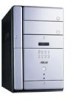
System introduction Chapter 1 This chapter gives a general description of the ASUS Terminator 2. The chapter lists the system features including introduction on the front and rear panel, and internal components. MODE ASUS Terminator 2 barebone system - Asus T2-P | T2-P User Manual - Page 12
2! The ASUS Terminator 2 is an all-in-one barebone system with a versatile home entertainment feature. The system comes in a stylish mini-tower casing, and powered by the ASUS P4P8T motherboard that supports Intel® Pentium® 4 Northwood/ Prescott processor with 800MHz FSB, and up to 2GB system memory - Asus T2-P | T2-P User Manual - Page 13
in different modes. In CD mode, plays or pauses an audio CD track. In Radio mode, scans the available FM stations when pressed for less than 2 seconds or presets a station when pressed for more than 2 seconds. Refer to page 60 on how to preset a radio station. ASUS Terminator 2 barebone system 13 - Asus T2-P | T2-P User Manual - Page 14
In Radio mode, selects the previous preset station. 16. NEXT button . Press this button to perform various functions in different modes. In CD mode, selects the next audio track. In Radio mode, selects the next preset station. 17. Volume down button -. Press this button to decrease the system volume - Asus T2-P | T2-P User Manual - Page 15
front panel doors by pressing the mark. Deluxe model (with 3-in-1 PCI card upgrade) 19 20 Standard model 19 20 21 22 23 24 MODE storage card. 22. Memory Stick®/Memory Stick Pro™ card slot. This slot is for a Memory Stick®/Memory Stick Pro™ storage card. ASUS Terminator 2 barebone system 15 - Asus T2-P | T2-P User Manual - Page 16
port connects a microphone. 27. USB 2.0 ports 2.0. These Universal Serial Bus 2.0 (USB 2.0) ports are available for connecting USB 2.0 devices such as a port . This port provides high-speed connectivity for IEEE 1394-compliant audio/video devices, storage peripherals, and other PC devices. 29. 6- - Asus T2-P | T2-P User Manual - Page 17
includes the power connector and several I/O ports that allow convenient connection of devices. Deluxe model ( specification. 5. PS/2 mouse port . This green 6-pin connector is for a PS/2 mouse. 6. PS/2 keyboard port . This purple 6-pin connector is for a PS/2 keyboard. ASUS Terminator 2 barebone - Asus T2-P | T2-P User Manual - Page 18
ventilation inside the system chassis. 16. Radio antenna port. This port connects an optional radio antenna. 17. Power supply unit fan. This fan provides ventilation inside the power supply unit. 18. Power connector. This connector is for the power cable and plug. 18 Chapter 1: System introduction - Asus T2-P | T2-P User Manual - Page 19
selector. This switch allows you to adjust the system input voltage according to the voltage supply in your area. See the "Voltage selector" section on page 40 before adjusting this switch data. See page 62 for the wireless LAN adapter LED indications. ASUS Terminator 2 barebone system 19 - Asus T2-P | T2-P User Manual - Page 20
to Chapter 2 for instructions on installing additional system components. 1 6 3 2 9 8 7 4 5 10 11 12 1. Optical drive 2. 5.25-inch empty optical drive bay 3. Floppy disk drive 4. Front panel cover 5. Hard disk drive metal tray 6. Chassis fan 7. ASUS P4P8T motherboard 8. DIMM sockets 9. CPU - Asus T2-P | T2-P User Manual - Page 21
of the audio CD track being played. In Radio mode, the LED panel displays the station preset number and station frequency. FM radio mode • Refer to page 59-60 for details on the Audio DJ feature. • The Audio DJ feature is available only on deluxe models. ASUS Terminator 2 barebone system 21 - Asus T2-P | T2-P User Manual - Page 22
22 Chapter 1: System introduction - Asus T2-P | T2-P User Manual - Page 23
Basic installation Chapter 2 This chapter provides step-by-step instructions on how to install components in the system. MODE ASUS Terminator 2 barebone system - Asus T2-P | T2-P User Manual - Page 24
power supply case, before handling components to avoid damaging them due to static electricity. • Hold components by the edges to avoid touching the ICs on them. • Whenever you uninstall any component, place it on a grounded antistatic pad or in the bag that came with the component. The motherboard - Asus T2-P | T2-P User Manual - Page 25
chassis. 1 1 2. Use a Phillips screw driver to remove the cover screws. Keep the screws for later use. 2 3. Slightly pull the cover toward the rear panel until the side tabs are disengaged from the chassis. 4. Lift the cover, then set aside. 2 2 4 3 3 ASUS Terminator 2 barebone system 25 - Asus T2-P | T2-P User Manual - Page 26
the front 4 6 panel for about half an inch. 6. Slightly lift the PSU. 5 7. Disconnect the power plugs on the motherboard, then set the PSU aside. When removing the PSU, 7 make sure to hold or support it firmly. The unit may accidentally drop and damage the other system 7 components. 26 - Asus T2-P | T2-P User Manual - Page 27
2.5 Installing a CPU The P4P8T motherboard comes with a surface mount 478-pin Zero Insertion Force (ZIF) socket. This socket is designed for Intel® Pentium® of the retention module, then lift. 5. Do steps 1 to 4 to remove the second retention bracket. 4 ASUS Terminator 2 barebone system 3 27 - Asus T2-P | T2-P User Manual - Page 28
7. Lift the CPU fan and heatsink 7 assembly, then set aside. 6 2.5.2 CPU installation To install the CPU: 1. Locate the 478-pin CPU socket on the motherboard. 2. Unlock the socket by pressing the lever sideways then lifting it up to a 90° angle. 3. Position the CPU above the socket such that its - Asus T2-P | T2-P User Manual - Page 29
assembly in place. 4 7 5 6. Follow steps 2 to 5 to re-install the second retention bracket. 7. Connect the CPU fan cable to the CPU fan connector on the motherboard. ASUS Terminator 2 barebone system 29 - Asus T2-P | T2-P User Manual - Page 30
the same CAS latency. For optimum compatibility, it is recommended that you obtain memory modules from the same vendor. • This motherboard only supports x4, x8, x16 chips/per module DDR DIMMs. • Make sure that the memory frequency matches the CPU FSB (Front Side Bus). Refer to Table 2. 30 Chapter - Asus T2-P | T2-P User Manual - Page 31
motherboard supports different memory frequencies depending on the CPU FSB (Front Side Bus) and the type of DDR DIMM. CPU FSB 800 MHz 533 MHz 400 MHz DDR DIMM Type PC3200/PC2700*/PC2100 PC2700/PC2100 PC2100 Memory into a socket to avoid damaging the DIMM! ASUS Terminator 2 barebone system 31 - Asus T2-P | T2-P User Manual - Page 32
, USB card, and other cards that comply with PCI specifications. AGP slot The AGP slot supports AGP 8X (+0.8V) cards and AGP 4X (+1.5V) cards. When you buy an AGP card, make sure that you ask for one with +0.8V or +1.5V specification. Install only +0.8V or +1.5V AGP cards. The P4P8T motherboard does - Asus T2-P | T2-P User Manual - Page 33
press firmly until the card is completely seated on the slot. 5. Replace the expansion card lock to secure the card to the chassis. 4 PCI card 5 ASUS Terminator 2 barebone system 33 - Asus T2-P | T2-P User Manual - Page 34
HC3 Onboard USB 2.0 controller Onboard LAN Onboard Audio A B CDE -- shared -- -- -- shared shared -- -- -- shared -- -- -- -- -- -- -- shared -- -- -- shared -- -- shared shared -- -- -- FGH used -- used -- -- -- -- When using a PCI card on shared slots, ensure that the drivers support "Share - Asus T2-P | T2-P User Manual - Page 35
until it detaches from the chassis, then set it aside. On Deluxe models, disconnect the LED panel and the front audio button panel cables from their respective connectors before removing the front panel drive with two screws on one side of the bay. 6 5 7 ASUS Terminator 2 barebone system 35 - Asus T2-P | T2-P User Manual - Page 36
Connect a power cable from the power supply unit to the power connector at motherboard. See page 84 for the location of the CD audio connector. 13. Re-install the front panel cover by aligning its hooks with the chassis holes. On Deluxe models, re-connect the LED panel and the front 13 audio - Asus T2-P | T2-P User Manual - Page 37
holes. 5. Secure the HDD with four screws. Lock slots Tray locks 5 4 5 Configure your hard disk drive as Master device before connecting the IDE cable and power plug. Refer to the HDD documentation on how to set the drive as a Master device. ASUS Terminator 2 barebone system 37 - Asus T2-P | T2-P User Manual - Page 38
the IDE connector on the drive. 9. Connect a 4-pin power plug from the power supply unit to the HDD power connector. 8 10. Connect the other end of the 9 IDE ribbon cable to the primary IDE connector (blue connector labeled PRI_IDE) on the motherboard. See page 82 for the location of the - Asus T2-P | T2-P User Manual - Page 39
power supply unit Re-install the power supply unit (PSU) after installing the system components and reconnecting the cables, . To reinstall the PSU: 1. Connect the 4-pin 12V and the 20-pin ATX power PSU cables do not interfere with the CPU and/or chassis fans. 5 ASUS Terminator 2 barebone system 39 - Asus T2-P | T2-P User Manual - Page 40
of the floppy disk drive. 7. Connect the 4-pin power plug(s) to the power connector of the optical drive(s). 8. Connect the 4-pin power plug to the power connector of the hard disk drive. See the Appendix for the power supply specifications. Voltage selector The PSU has a 115V/230V voltage - Asus T2-P | T2-P User Manual - Page 41
cover as shown. 4. Push the cover slightly toward 2 the front panel until it fits in 4 place. 5. Secure the cover with three screws you earlier removed. 5 ASUS Terminator 2 barebone system 41 - Asus T2-P | T2-P User Manual - Page 42
2.12 Connecting external devices To the front panel Standard/ Deluxe model Headphone Mic Scanner Audio Device Standard/ Deluxe model (with 3-in-1 PCI card upgrade) Headphone Mic 42 Scanner Camera HDD Audio Device Chapter 2: Basic installation - Asus T2-P | T2-P User Manual - Page 43
To the rear panel Telephone Joystick Serial mouse PS/2 KB VGA monitor Recorder Card Reader RJ-11 socket RJ-45 Mic PS/2 Mouse Printer Line Out Power outlet ASUS Terminator 2 barebone system 43 - Asus T2-P | T2-P User Manual - Page 44
44 Chapter 2: Basic installation - Asus T2-P | T2-P User Manual - Page 45
Starting up Chapter 3 This chapter helps you power up the system and install drivers and utilities from the support CD. MODE ASUS Terminator 2 barebone system - Asus T2-P | T2-P User Manual - Page 46
only on Deluxe models. See page 59 for details. Press to put the system in Audio DJ mode MODE Press to enter the system OS In Windows® mode, pressing the button shuts down, restarts, or puts the system in sleep mode (S3) depending on the OS setting. 3.3 Support CD information The support CD that - Asus T2-P | T2-P User Manual - Page 47
the Intel Chipset INF Update Program. Intel(R) Extreme Graphics Driver Click this item to install the Intel Extreme Graphics driver. AD1888 SoundMAX® Audio Driver This item installs the AD1888 audio driver and SoundMax® application. See page 51 for details. ASUS Terminator 2 barebone system 47 - Asus T2-P | T2-P User Manual - Page 48
. This item appears only on Deluxe models. ASUS Wireless LAN Adapter Driver This item installs the ASUS wireless LAN driver. See page 61 for details. 3.3.3 Utilities menu The Utilities menu shows the applications and other software that the motherboard supports. LifeView TVR Application Click this - Asus T2-P | T2-P User Manual - Page 49
problems. This utility helps you keep your computer in a healthy operating condition. Install ASUS Update This item installs the ASUS Update that allows you to update the motherboard BIOS and drivers. This utility requires an Internet connection either through a network or an Internet Service - Asus T2-P | T2-P User Manual - Page 50
3.3.5 Other information The icons on the top right side of the screen provide additional information on the motherboard and the contents of the support CD. 50 Chapter 3: Starting up - Asus T2-P | T2-P User Manual - Page 51
Driver and Application from the support CD to activate the 6-channel audio feature. You must use 4-channel or 6-channel speakers for this setup. Setting to multi-channel audio After installing the audio driver, follow these instructions to adjust the audio . ASUS Terminator 2 barebone system 51 - Asus T2-P | T2-P User Manual - Page 52
Test button to display the Test Listening Environment window. 7. Select the audio test path from the drop-down menu. button. While testing, you will see a black circle moving on the screen indicating the audio path. The Play Test Noise button becomes Stop Playing button. Click this button at any - Asus T2-P | T2-P User Manual - Page 53
window. 2. Check the box opposite Mic2 Select to enable the front panel microphone. 3. Click Close for the new settings to take effect. The rear panel Mic port (pink) is automatically disabled when you enable the front panel Mic port. Only one Mic port works at a time. ASUS Terminator 2 barebone - Asus T2-P | T2-P User Manual - Page 54
Radio Application from the Utilities tab of the support CD. See page 48 for details. 2. After installing the application, click Start > All Programs > ASUS > ASUS Radio Player V1.0 > ASUS Radio Player V1.0 from the Windows® desktop. 3. The ASUS Radio Player panel appears. Station frequency Preset - Asus T2-P | T2-P User Manual - Page 55
a stored radio station: 1. Click the Edit button. An Edit Channel window appears. 2. Select a radio station you wish to edit, then click the Edit button. 3. Another Edit Channel window appears. 4. Edit the station frequency and name. Click OK when finished. ASUS Terminator 2 barebone system 55 - Asus T2-P | T2-P User Manual - Page 56
3.4.3 ASUS Instant Music The motherboard is equipped with a BIOS-based audio playback feature called Instant Music. This feature is supported by the onboard audio AC'97 CODEC, and requires an optical drive (CD-ROM, DVD-ROM, CD-RW, or DVD-RW). • Instant Music only supports CDs in audio format. • - Asus T2-P | T2-P User Manual - Page 57
Bar>. 7. Refer to the Instant Music keyboard label to select other tracks or control the volume. 8. Press or once to stop playing the audio CD. Press or again to eject the CD. ASUS Terminator 2 barebone system 57 - Asus T2-P | T2-P User Manual - Page 58
® TVR Application allows you to watch and record TV in the Terminator 2 system. Install this application if you purchased a 3-in-1 Windows® desktop. 3. The Lifeview TVR panel appears. Refer to the LifeView® TVR user manual in the Drivers folder (Drivers\TV\TV Manual\Manual_ENG.pdf) of the support CD - Asus T2-P | T2-P User Manual - Page 59
entering the Terminator 2 operating system. To put the system in Audio DJ mode: 1. Connect the system power plug to an electrical outlet. 2. Press the CD button ( ) on the front panel to put the system in Audio DJ mode. 3.5.1 Playing an audio CD/DVD To play an audio CD/DVD: 1. Insert an audio CD/DVD - Asus T2-P | T2-P User Manual - Page 60
3.5.3 Presetting a station To preset a radio station: 1. Put the Audio DJ in radio mode. 2. Select the radio station you wish to preset by pressing the PLAY/PAUSE ( / ) volume. Connect a headphone or PC speakers to the rear or front panel Line Out port for audio output. 60 Chapter 3: Starting up - Asus T2-P | T2-P User Manual - Page 61
adapter to other wireless clients) network types • Windows® 2000/XP compatible • Stand-alone dipolar antenna The wireless LAN adapter operating distance may be shorter if there are walls, barriers, or interferences in the home layout or operating environment. ASUS Terminator 2 barebone system 61 - Asus T2-P | T2-P User Manual - Page 62
network. 3.6.2 Antenna installation Connect the dipolar antenna to the antenna connector (male) of the wireless LAN adapter before installing the device drivers and utilities. Place the antenna at an elevated location to receive or transmit better signal. Do not place the antenna under your table - Asus T2-P | T2-P User Manual - Page 63
. Click EXIT to close the installation window. Refer to the ASUS Wireless LAN Adapter user guide in the support CD for details. You may access the user guide by clicking the Read/Install User Documentation from the wireless LAN adapter installation window. ASUS Terminator 2 barebone system 63 - Asus T2-P | T2-P User Manual - Page 64
configures network settings. The Control Center Utility starts automatically when the system boots and displays the Control Center icon in the Windows® taskbar. The Control Center icon serves as an application launcher, and indicator of signal quality and Internet connection. Control Center icons - Asus T2-P | T2-P User Manual - Page 65
displays the radio communication status. Click the Disable Radio button if you wish to disable radio communication with an access point or a Wi-Fi device. ASUS Terminator 2 barebone system 65 - Asus T2-P | T2-P User Manual - Page 66
host and Ethernet adapter configurations. IP Config displays TCP/IP information including the IP address, subnet mask, default gateway, DNS and Windows Internet Naming Service (WINS) configurations. Use the IP Config tab to verify your network settings. IP Release. Releases the DHCP IP address for - Asus T2-P | T2-P User Manual - Page 67
LAN and wired LAN (Ethernet) via the AP. Select the Ad Hoc mode to communicate directly with other wireless clients within the adapter operating range. ASUS Terminator 2 barebone system 67 - Asus T2-P | T2-P User Manual - Page 68
features. The CAM (Constantly Awake mode) is recommended for systems running on AC power. Other options include MAX_PSP (Maximum Power Savings) and Fast_PSP (Fast power-saving mode) Others. Click the WEP or Advanced link to open the Encryption or Advanced property tab sheet. Config - Encryption - Asus T2-P | T2-P User Manual - Page 69
more secure than automatically generated encryptions. • Use Manual Assignment instead of Automatic Generation if you are not sure whether other wireless clients use the same algorithm as that of wireless LAN adapter. • Keep a record of the WEP encryption keys. ASUS Terminator 2 barebone system 69 - Asus T2-P | T2-P User Manual - Page 70
wireless LAN adapter. The Soft AP tab appears only on systems running on Windows® XP. SoftAP/STA Mode. This field allows you to select the wireless connection may be bridged with the adapter. Refer to user guide in the support CD for detailed information on ICS and network bridge features. Enable - Asus T2-P | T2-P User Manual - Page 71
window displays the available networks within the wireless LAN adapter range and the following network settings: BSSID - The IEEE MAC address of the available wireless networks. SSID - SSID (service the software version, driver version, and copyright information ASUS Terminator 2 barebone system 71 - Asus T2-P | T2-P User Manual - Page 72
Wireless Settings utility window. Cancel. Click to cancel any changes made on the adapter configuration. Clicking Cancel closes the Wireless Settings utility window. Help. Click (AP) mode. Refer to user guide in the support CD before setting the adapter in soft AP mode. 72 Chapter 3: Starting up - Asus T2-P | T2-P User Manual - Page 73
LAN adapter radio OFF. Search & Connect - View available wireless networks within range. Wireless Option - Sets your Windows® XP wireless networking environment. The Control Center left-click menu is available only when the adapter is set to Station Mode (STA). ASUS Terminator 2 barebone system 73 - Asus T2-P | T2-P User Manual - Page 74
74 Chapter 3: Starting up - Asus T2-P | T2-P User Manual - Page 75
Motherboard info Chapter 4 This chapter gives information about the motherboard that comes with the system. This chapter includes the motherboard layout, jumper settings, and connector locations. MODE ASUS Terminator 2 barebone system - Asus T2-P | T2-P User Manual - Page 76
module) Socket 478 CPU_FAN CHA_FAN Super I/O Flash BIOS ATX12V Intel 865G AGP1 PCI Slot 1 SB_PWR P4P8T CR2032 3V Lithium Cell CMOS Power USB56 USB78 BUZZER ® Intel ICH5 SATA2 SATA1 CLRTC PANEL SEC_IDE PRI_IDE ATX Power Connector FLOPPY 20.06cm (7.9in) 76 Chapter 4: Motherboard info - Asus T2-P | T2-P User Manual - Page 77
RAM CLRTC 12 23 Normal (Default) Clear CMOS • Except when clearing the RTC RAM, never remove the cap on CLRTC jumper default position. Removing the cap will cause system boot failure. • The system automatically turns on when you clear the CMOS after first reboot. ASUS Terminator 2 barebone - Asus T2-P | T2-P User Manual - Page 78
USBP2- USBP2+ GND NC USB Power USBP3- USBP3+ GND P4P8T ® P4P8T USB Port 1 5 USB56 6 10 2. Front panel audio connector (10-1 pin FP_AUDIO) This interface is connected to the J1 connector on the front panel I/O daughterboard to support the front panel audio I/O ports. Line out_L NC Line - Asus T2-P | T2-P User Manual - Page 79
on the storage card reader daughterboard. For Basic models, you may use the USB78 connector to install a USB module for two additional USB ports. USB78 USB Power USBP2- USBP2+ GND NC P4P8T ® P4P8T USB Port USB Power USBP3- USBP3+ GND 1 5 6 10 ASUS Terminator 2 barebone system 79 - Asus T2-P | T2-P User Manual - Page 80
AC_SYNC AC_SDIN1 GND MDC_BITCLK 6. I/O extension module (22-pin IOC_MB) This connector is for the CGAEX extension module. The CGAEX extension module supports the rear panel GAME/MIDI and serial ports. P4P8T ® P4P8T IOC_MB Connector COM1 GAME ® CGAEX IOC_DC 80 Chapter 4: Motherboard info - Asus T2-P | T2-P User Manual - Page 81
+5V Standby Power Good Ground +5.0 Volts Ground +5.0 Volts Ground +3.3 Volts +3.3 Volts +5.0 Volts +5.0 Volts -5.0 Volts Ground Ground Ground Power Supply On Ground -12.0Volts +3.3Volts P4P8T ® P4P8T ATX Power Connector ATX12V +12V DC COM +12V DC COM ASUS Terminator 2 barebone system 81 - Asus T2-P | T2-P User Manual - Page 82
allows up to 150 MB/s data transfer rate, faster than the standard parallel ATA with 133MB/s (Ultra ATA133). SATA2 GND RSATA_TXP2 RSATA_TXN2 GND RSATA_RXP2 RSATA_RXN2 GND P4P8T ® P4P8T SATA Connectors 82 GND RSATA_TXP1 RSATA_TXN1 GND RSATA_RXP1 RSATA_RXN1 GND SATA1 Chapter 4: Motherboard info - Asus T2-P | T2-P User Manual - Page 83
. BIOS item Windows® 2000/XP Windows® 98/ME/NT4.0 A B C Onboard IDE Operate Mode Enhanced Mode Compatible Mode Compatible Mode Compatible Mode Enhanced Mode Support On S-ATA - - - IDE Port Settings - Primary P-ATA+S-ATA Sec. P-ATA+S-ATA P-ATA Ports Only ASUS Terminator 2 barebone - Asus T2-P | T2-P User Manual - Page 84
Channel Ground Left Audio Channel Right Audio Channel Ground Left Audio Channel P4P8T ® P4P8T Internal Audio Connectors 12. Floppy disk drive connector (34-1 pin FLOPPY) This connector supports the provided floppy drive ribbon cable. After connecting one end to the motherboard, connect the other - Asus T2-P | T2-P User Manual - Page 85
mode for more than 4 seconds turns the system OFF. • IDE LED Lead This 2-pin connector supplies power to the hard disk drive activity LED. The read or write activities of any device connected to the primary or secondary IDE connector cause this LED to light up. ASUS Terminator 2 barebone system 85 - Asus T2-P | T2-P User Manual - Page 86
86 Chapter 4: Motherboard info - Asus T2-P | T2-P User Manual - Page 87
Chapter 5 This chapter tells how to change system settings through the BIOS Setup menus and describes the BIOS parameters. BIOS setup MODE ASUS Terminator 2 barebone system 87 - Asus T2-P | T2-P User Manual - Page 88
the support CD when the BIOS gets corrupted.) 4. ASUS Update (Updates the BIOS in Windows® environment.) Refer to the corresponding section for each utility. • It is recommended that you save a copy of the original motherboard BIOS file to a bootable floppy disk in case you need to restore the BIOS - Asus T2-P | T2-P User Manual - Page 89
store the file. A:\>afudos /oMYBIOS03.rom AMI Firmware Update Utility - Version 1.10 Copyright (C) 2002 American Megatrends, Inc. All rights reserved. Reading flash ..... done A:\> When the BIOS copy process is complete, the utility returns to the DOS prompt. ASUS Terminator 2 barebone system 89 - Asus T2-P | T2-P User Manual - Page 90
Visit the ASUS website (www.asus.com) to download the latest BIOS file for your motherboard. Save the BIOS file to a bootable floppy disk. Write down the BIOS file name to a piece of paper. You need to type the exact BIOS file name at the prompt. 2. Copy the AFUDOS.EXE utility from the support CD to - Asus T2-P | T2-P User Manual - Page 91
When the BIOS update process is complete, the utility returns to the DOS prompt. A:\>afudos /ip4p8t.rom AMI Firmware Update done Erasing flash .... done Writing flash .... 0x0008CC00 (9%) Verifying flash .. done A:\> 5. Reboot the system from the hard disk. ASUS Terminator 2 barebone system 91 - Asus T2-P | T2-P User Manual - Page 92
by simply pressing + during the Power-On Self Tests (POST). To update the BIOS using ASUS EZ Flash: 1. Visit the ASUS website (www.asus.com) to download the latest BIOS file for your motherboard and rename it to P4P8T.ROM. Save the BIOS file to a floppy disk. 2. Reboot the system - Asus T2-P | T2-P User Manual - Page 93
you to restore BIOS from the motherboard support CD, or from a floppy disk that contains the BIOS file, in case the current BIOS on the motherboard fails or gets corrupted. • Prepare the support CD that came with the motherboard or a floppy disk that contains the motherboard BIOS (P4P8T.ROM) before - Asus T2-P | T2-P User Manual - Page 94
in the drive. 3. Place the support CD in the optical drive. The support CD contains the original BIOS for this motherboard. Bad BIOS checksum. Starting BIOS recovery... Checking for floppy... Floppy not found! Checking for CD-ROM... CD-ROM found. Reading file "p4p8t.rom". Completed. Start flashing - Asus T2-P | T2-P User Manual - Page 95
update the motherboard BIOS in Windows® environment. This utility is available in the support CD that comes with the motherboard package. ASUS Update requires an Internet connection either through a network or an Internet Service Provider (ISP). To install ASUS Update: 1. Place the support CD in the - Asus T2-P | T2-P User Manual - Page 96
Auto Select. Click Next. 4. From the FTP site, select the BIOS version that you wish to download. Click Next. 5. Follow the screen instructions to complete the update process. If you selected the option to update the BIOS from a file, a window pops up prompting you to locate the file. Select the - Asus T2-P | T2-P User Manual - Page 97
submenus and make your selections among the predetermined choices. Because the BIOS software is constantly being updated, the following BIOS setup screens and descriptions are for reference purposes only, and may not exactly match what you see on your screen. ASUS Terminator 2 barebone system 97 - Asus T2-P | T2-P User Manual - Page 98
[11:10:19] [Thu, 09/27/2003] [1.44M, 3.5 in.] [English] [ST321122A] [ASUS CDS520/] [Not Detected] [Not Detected] [Not Detected] [Not Detected] Use [ENTER], [TAB] For changing the advanced system settings Power For changing the advanced power management (APM) configuration Boot For 5: BIOS setup - Asus T2-P | T2-P User Manual - Page 99
that do not fit on the screen. Pop-up window Scroll bar Press Up/Down arrow keys or PageUp/PageDown keys to display the other items on the screen. 5.2.9 General help At the top right corner of the menu screen is a brief description of the selected item. ASUS Terminator 2 barebone system 99 - Asus T2-P | T2-P User Manual - Page 100
overview of the basic system information. Refer to section 5.2.1 BIOS menu screen" for information on the menu screen items and System Information [11:10:19] [Thu, 09/27/2003] [1.44M, 3.5 in.] [ST321122A] [ASUS CDS520/] [Not Detected] [Not Detected] [Not Detected] [Not Detected] Use [ENTER], [TAB - Asus T2-P | T2-P User Manual - Page 101
are auto-detected by BIOS and are not user-configurable are specifically configuring a CD-ROM drive supports multi-sector transfer feature. When set to Disabled, the data transfer from and to the device occurs one sector at a time. Configuration options: [Disabled] [Auto] ASUS Terminator 2 barebone - Asus T2-P | T2-P User Manual - Page 102
Mode Enhanced Mode Support On IDE Detect Windows® ME/98/NT4.0. Configuration options: [Compatible Mode] [Enhanced Mode] Refer to the "Parallel ATA and Serial ATA device configuration" section on page 83 for correct IDE configuration settings in different operating systems. 102 Chapter 5: BIOS - Asus T2-P | T2-P User Manual - Page 103
Support options and encounter problems, revert to the Memory Size : 256MB AMI BIOS This item displays the auto-detected BIOS information. Processor This item displays the auto-detected CPU specification. System Memory This item displays the auto-detected system memory. ASUS Terminator 2 barebone - Asus T2-P | T2-P User Manual - Page 104
. CPU Configuration Chipset Onboard Devices Configuration PCI PnP USB Configuration Instant Music Configuration Configure CPU. 5.4.1 CPU items in this menu show the CPU-related information auto-detected by BIOS. Configure advanced CPU settings Manufacturer Brand String Frequency FSB Speed : - Asus T2-P | T2-P User Manual - Page 105
you to enable or disable the CPUID maximum value limit support for older OS. Configuration options: [Disabled] [Enabled] Video Memory Graphics Aperture Size [AGP/Int-VGA] [Enabled, 8MB] [ 64MB] Boot Display Device Flat Panel type TV Standard [Auto ] [2.70V] ASUS Terminator 2 barebone system 105 - Asus T2-P | T2-P User Manual - Page 106
(Serial Presence Detect). Configuration options: [Enabled] [Disabled] When you disable this option, you may manually set the DRAM timing parameters through the DRAM sub-items listed below. DRAM CAS# Latency [2.5 Clocks] : [Internal VGA] [AGP/PCI] [PCI/AGP] [PCI/Int-VGA] 106 Chapter 5: BIOS setup - Asus T2-P | T2-P User Manual - Page 107
Size [64MB] This parameter allows you to select the mapped memory for AGP graphic data. Configuration options: [4MB] [8MB] Standard [Auto] This parameter allows you to select the TV standard ] [PAL_60] MPS Revision [1.4] Configuration options: [1.4] [1.1] ASUS Terminator 2 barebone system 107 - Asus T2-P | T2-P User Manual - Page 108
] [EPP+ECP] [1.9] [DMA3] [IRQ7] [Enabled] [Disabled] OnBoard AC'97 Audio [Auto] [Auto] allows the BIOS to detect whether you are using any audio device. If an audio device is detected, the onboard audio controller is enabled; if no audio device is detected, the controller is disabled. Configuration - Asus T2-P | T2-P User Manual - Page 109
[Disabled] Allows you to select the MIDI port address or to disable the port. Configuration options: [Disabled] [200/300] [200/330] [208/300] [208/330] ASUS Terminator 2 barebone system 109 - Asus T2-P | T2-P User Manual - Page 110
resources for either PCI/PnP or legacy ISA devices, and setting the memory size block for legacy ISA devices. Take caution when changing the settings and Play operating system. Plug and Play O/S [No] When set to [No], BIOS configures all the devices in the system. When set to [Yes] and if you - Asus T2-P | T2-P User Manual - Page 111
. Configuration options: [Disabled] [Enabled] IRQ xx [Available] When set to [Available], the specific IRQ is free for use of PCI/PnP devices. When set to [Reserved], the IRQ is reserved for legacy ISA devices. Configuration options: [Available] [Reserved] ASUS Terminator 2 barebone system 111 - Asus T2-P | T2-P User Manual - Page 112
, the item shows None. USB Function [8 USB Ports] Allows you to set the number of USB ports to activate. Configuration options: [Disabled] [2 USB Ports] [4 USB Ports] [6 USB Ports] [8 USB Ports] Legacy USB Support [Auto] Allows you to enable or disable support for legacy USB devices. Setting to Auto - Asus T2-P | T2-P User Manual - Page 113
[10 Sec ] [20 Sec] [30 Sec] [40 Sec] Emulation Type [N/A] When set to Auto, USB devices less than 530MB will be emulated as floppy drive, and the remaining drives as hard drives. Forced FDD Emulation Type items appear only when there are installed USB devices. ASUS Terminator 2 barebone system 113 - Asus T2-P | T2-P User Manual - Page 114
BIOS. Configuration options: [Disabled] [Enabled] • When Instant Music is enabled, the PS/2 keyboard power up feature is automatically disabled. See page 54 for details on the ASUS the radio region of the ASUS FM radio module is set to Europe. If you purchased the Terminator 2 system outside Europe ( - Asus T2-P | T2-P User Manual - Page 115
2.0 specifications. Configuration options: [No] [Yes] 5.5.4 ACPI APIC Support [Enabled] Allows you to enable or disable the ACPI support in the ASIC. When set to Enabled, the ACPI APIC table pointer is included in the RSDT pointer list. Configuration options: [Disabled] [Enabled] ASUS Terminator - Asus T2-P | T2-P User Manual - Page 116
system state before the AC power loss. Configuration options: [Power Off] [Power On] [Last State] Power On By PS/2 Devices [Disabled] This parameter allows you to use specific keys on the keyboard or the mouse to turn on the system. This feature requires an ATX power supply that provides at least 1A - Asus T2-P | T2-P User Manual - Page 117
requires an ATX power supply that provides at least 1A on the +5VSB lead. Configuration options: [Disabled] [Enabled] Power On By RTC power fan speeds in rotations per minute (RPM). If any of the fans is not connected to the motherboard, the specific field shows N/A. ASUS Terminator 2 barebone - Asus T2-P | T2-P User Manual - Page 118
, the following error message appears: "Hardware Monitor found an error. Enter Power setup menu for details". You will then be prompted to "Press F1 Function [Enabled] This item allows you to enable or disable the ASUS Smart Q-Fan feature that smartly adjusts the fan speeds for more BIOS setup - Asus T2-P | T2-P User Manual - Page 119
Boot Device 2nd Boot Device 3rd Boot Device [First Floppy Drive] [PM-ST320413A] [PS-ASUS CD-S340] Specifies the boot sequence from the available devices. A device enclosed in parenthesis has in the system. Configuration options: [xxxxx Drive] [Disabled] ASUS Terminator 2 barebone system 119 - Asus T2-P | T2-P User Manual - Page 120
xxxxx Drive] [Disabled] 5.6.3 CDROM Drives CDROM Drives 1st Drive 2nd Drive [SM-ASUS DRW-0402P/D] [SS-ASUS CD-S520/A] Specifies the boot sequence from the available devices. 1st ~ xxth Drive [SM Secondary Slave device. Configuration options: [ xxxxx Drive] [Disabled] 120 Chapter 5: BIOS setup - Asus T2-P | T2-P User Manual - Page 121
[Force BIOS] [Keep Current] Bootup Num-Lock [On] Allows you to select the power-on state for the NumLock. Configuration options: [On] [Off] PS/2 Mouse Support [Auto] Allows you to enable or disable support for PS/2 mouse. Configuration options: [Auto] [Disabled] [Enabled] ASUS Terminator 2 barebone - Asus T2-P | T2-P User Manual - Page 122
] [Disabled] Interrupt 19 Capture [Disabled] When set to [Enabled], this function allows the option ROMs to trap Interrupt 19. Configuration options: [Disabled] [Enabled] 122 Chapter 5: BIOS setup - Asus T2-P | T2-P User Manual - Page 123
Supervisor Password then press Enter. The message "Password Uninstalled" appears. If you forget your BIOS password, you can clear clear it by erasing the CMOS Real Time Clock (RTC) RAM. Refer to section "4.3 Jumper" for instructions on erasing the RTC RAM. ASUS Terminator 2 barebone system 123 - Asus T2-P | T2-P User Manual - Page 124
your password. The User Password item now shows Installed. To change the user password, follow the same steps as in setting a user password. 124 Chapter 5: BIOS setup - Asus T2-P | T2-P User Manual - Page 125
the BIOS items, and save or discard your changes to the BIOS items. RAM. The CMOS RAM is sustained by an onboard backup battery and stays on even when the PC is turned off. When you select this option, a confirmation window appears. Select [Yes] to save changes and exit. ASUS Terminator 2 barebone - Asus T2-P | T2-P User Manual - Page 126
the BIOS asks for a confirmation before exiting. Discard Changes This option allows you to discard the selections you made and restore the previously you select this option or if you press , a confirmation window appears. Select [Yes] to load default values. Select Exit Saving Changes or - Asus T2-P | T2-P User Manual - Page 127
Appendix The Appendix includes the power supply unit specification and IEEE 802.11b channels for the wireless LAN adapter. MODE ASUS Terminator 2 barebone system Appendix - Asus T2-P | T2-P User Manual - Page 128
A.1 Power supply specifications Input characteristics Input Voltage Range Range 1 Range 2 Input Frequency Range Maximum Input AC Current Inrush Current Efficiency Current Harmonic EPA Min Nom Max 90V 115V - Asus T2-P | T2-P User Manual - Page 129
A.2 Wireless LAN adapter channels The IEEE 802.11b standard for Wireless LAN allocated the 2.4 GHz frequency band into 14 overlapping operating channels. Each (RTT&E/EMC/LVD) Channels 1 to 13 Iceland (RTT&E/EMC/LVD) Channels 1 to 13 (continued next page) ASUS Terminator 2 barebone system A-3 - Asus T2-P | T2-P User Manual - Page 130
Country/Region (Regulating Body) Ireland (RTT&E/EMC/LVD) Italy (RTT&E/EMC/LVD) Japan (TELEC) Luxembourg (RTT&E/EMC/LVD) Malaysia (SIRIM/CMC) Mexico Netherlands Antilles (RTT&E/EMC/LVD) Netherlands/Holland (RTT&E/EMC/LVD) New Zealand (PTC) Norway (RTT&E/EMC/LVD) Portugal (RTT&E/EMC/LVD) Saudi Arabia
-
 1
1 -
 2
2 -
 3
3 -
 4
4 -
 5
5 -
 6
6 -
 7
7 -
8
-
9
-
10
-
11
-
12
-
13
-
14
-
15
-
16
-
17
-
18
-
19
-
20
-
21
-
22
-
23
-
24
-
25
-
26
-
27
-
28
-
29
-
30
-
31
-
32
-
33
-
34
-
35
-
36
-
37
-
38
-
39
-
40
-
41
-
42
-
43
-
44
-
45
-
46
-
47
-
48
-
49
-
50
-
51
-
52
-
53
-
54
-
55
-
56
-
57
-
58
-
59
-
60
-
61
-
62
-
63
-
64
-
65
-
66
-
67
-
68
-
69
-
70
-
71
-
72
-
73
-
74
-
75
-
76
-
77
-
78
-
79
-
80
-
81
-
82
-
83
-
84
-
85
-
86
-
87
-
88
-
89
-
90
-
91
-
92
-
93
-
94
-
95
-
96
-
97
-
98
-
99
-
100
-
101
-
102
-
103
-
104
-
105
-
106
-
107
-
108
-
109
-
110
-
111
-
112
-
113
-
114
-
115
-
116
-
117
-
118
-
119
-
120
-
121
-
122
-
123
-
124
-
125
-
126
-
127
-
128
-
129
-
130
 |
 |

Barebone System
Model T2-P
Terminator 2
User Guide
MODE