Asus VINTAGE-PE1 Vintage-PE1 User''s Manual for English E2012
Asus VINTAGE-PE1 Manual
 |
View all Asus VINTAGE-PE1 manuals
Add to My Manuals
Save this manual to your list of manuals |
Asus VINTAGE-PE1 manual content summary:
- Asus VINTAGE-PE1 | Vintage-PE1 User''s Manual for English E2012 - Page 1
Vintage-PE1 Barebone System - Asus VINTAGE-PE1 | Vintage-PE1 User''s Manual for English E2012 - Page 2
E2012 First Edition April 2005 Copyright © 2005 ASUSTeK COMPUTER INC. All Rights Reserved. No part of this manual, including the products and software described in it, may be reproduced, transmitted, transcribed, stored in a retrieval system, or translated into any language in any form or by any - Asus VINTAGE-PE1 | Vintage-PE1 User''s Manual for English E2012 - Page 3
the CPU 2-5 2.4.2 Installling the CPU heatsink and fan 2-8 2.4.3 Uninstalling the CPU heatsink and fan 2-10 2.5 Installing a DIMM 2-12 2.5.1 Memory configurations 2-12 2.5.2 Installing a DIMM 2-14 2.5.3 Removing a DIMM 2-14 2.6 Expansion slots 2-15 2.6.1 Installing an expansion card 2-15 - Asus VINTAGE-PE1 | Vintage-PE1 User''s Manual for English E2012 - Page 4
system 3-2 3.2 Powering up 3-2 3.3 Support CD information 3-2 3.3.1 Running the support CD 3-3 3.3.2 Utilities menu 3-4 3.2.3 ASUS Contact information 3-5 Chapter 4: Motherboard Info 4.1 Introduction 4-2 4.2 Motherboard layout 4-2 4.3 Jumpers 4-3 4.4 Connectors 4-5 Chapter 5: BIOS - Asus VINTAGE-PE1 | Vintage-PE1 User''s Manual for English E2012 - Page 5
5-17 5.4.2 CPU Configuration 5-18 5.4.3 Chipset 5-19 5.4.4 Onboard Devices Configuration 5-20 5.4.5 PCI PnP 5-22 5.4.6 USB Configuration 5-23 5.4.7 Instant Music Configuration 5-24 5.5 Power menu 5-25 5.5.1 Suspend Mode 5-25 5.5.2 ACPI 2.0 Support 5-25 5.5.3 ACPI APIC Support 5-25 - Asus VINTAGE-PE1 | Vintage-PE1 User''s Manual for English E2012 - Page 6
a Class B digital device, pursuant to Part 15 of the FCC Rules. These limits used in accordance with manufacturer's instructions, may cause harmful interference to of shielded cables for connection of the monitor to the graphics card is required to assure compliance with FCC regulations. Changes or - Asus VINTAGE-PE1 | Vintage-PE1 User''s Manual for English E2012 - Page 7
power supply is broken, do not try to fix it by yourself. Contact a qualified service technician or your retailer. Operation safety • Before installing devices into the system . • If you encounter technical problems with the product, contact a qualified service technician or your retailer. Lithium- - Asus VINTAGE-PE1 | Vintage-PE1 User''s Manual for English E2012 - Page 8
and installation instructions about the ASUS Vintage-PE1 barebone system. This guide is intended for experienced users and integrators with hardware knowledge of personal computers. How this guide is organized This guide contains the following parts: 1. Chapter 1: System introduction This - Asus VINTAGE-PE1 | Vintage-PE1 User''s Manual for English E2012 - Page 9
T : Instructions that you MUST follow to complete a task. N O T E : Tips and additional information to aid in completing a task. Where to find more information Refer to the following sources for additional information and for product and software updates. 1. ASUS Websites The ASUS websites worldwide - Asus VINTAGE-PE1 | Vintage-PE1 User''s Manual for English E2012 - Page 10
Check your Vintage-PE1 system package for the following items. If any of the items is damaged or missing, contact your retailer immediately. Item description 1 . A S U S V i n t a g e - P E 1 b a r e b o n e s y s t e m with • ASUS motherboard • 300 W power supply unit w/ PFC • ASUS chassis 2. Cable - Asus VINTAGE-PE1 | Vintage-PE1 User''s Manual for English E2012 - Page 11
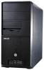
System introduction Chapter 1 This chapter gives a general description of the ASUS Vintage-PE1. The chapter lists the system features including introduction on the front and rear panel, and internal components. ASUS Vintage-PE1 - Asus VINTAGE-PE1 | Vintage-PE1 User''s Manual for English E2012 - Page 12
! The ASUS Vintage-PE1 is an all-in-one barebone system with a versatile home entertainment feature. The system comes in a stylish mini-tower casing and powered by the ASUS motherboard that supports the Intel® Pentium® 4 processor in the 775-land package with 800 MHz FSB and up to 2 GB system memory - Asus VINTAGE-PE1 | Vintage-PE1 User''s Manual for English E2012 - Page 13
t o n. Press this button to reboot the system without turning off the power. 5 . P o w e r b u t t o n. Press this button to turn the system on. 6 . H e a d p h 1394 port provides high-speed connectivity for audio/video devices, storage peripherals, PCs, or portable devices. ASUS Vintage-PE1 1-3 - Asus VINTAGE-PE1 | Vintage-PE1 User''s Manual for English E2012 - Page 14
1.3 Rear panel The system rear panel includes the power connector and several I/O ports that allow . This port connects a mouse, modem, or other devices that conforms with serial specification. 4 . P a r a l l e l p o r t . CD, DVD player, or other audio sources. 1-4 Chapter 1: System introduction - Asus VINTAGE-PE1 | Vintage-PE1 User''s Manual for English E2012 - Page 15
power to the power supply unit. 1 4 . C h a s s i s f a n v e n t . This vent is for the fan that provides ventilation inside the system chassis. 1 5 . I E E E 1 3 9 4 p o r t . This port connects IEEE 1394 devices such as digital still/video when installing expansion cards. ASUS Vintage-PE1 1-5 - Asus VINTAGE-PE1 | Vintage-PE1 User''s Manual for English E2012 - Page 16
Voltage selector The PSU has a 115 V/230 V voltage selector switch located beside the power connector. Use this switch to select the appropriate system input voltage according to the voltage supply in your area. If the voltage supply in your area is 100-127 V, set the switch to 115 V. If the voltage - Asus VINTAGE-PE1 | Vintage-PE1 User''s Manual for English E2012 - Page 17
1. 5.25-inch drive bay 2. Floppy disk drive bay 3. Front panel cover 4. Hard disk drive bay 5. Chassis fan 6. ASUS motherboard 7. DIMM sockets 8. LGA775 socket with PnP cap 9. AGP 8X slot 10. PCI slots 11. Serial ATA connectors 12. Expansion card slots 13. Power supply unit ASUS Vintage-PE1 1-7 - Asus VINTAGE-PE1 | Vintage-PE1 User''s Manual for English E2012 - Page 18
1-8 Chapter 1: System introduction - Asus VINTAGE-PE1 | Vintage-PE1 User''s Manual for English E2012 - Page 19
by adjusting the software settings. 1. Turn on the system and change the necessary BIOS settings, if any. See Chapter 5 for information on BIOS setup. 2. Assign an IRQ to the card. Refer to the tables on the next page. 3. Install the software drivers for the expansion card. ASUS Vintage-PE1 2-15 - Asus VINTAGE-PE1 | Vintage-PE1 User''s Manual for English E2012 - Page 20
this motherboard PCI 2.0 controller Onboard Azalia Audio Onboard IDE Controller Onboard cards on shared slots, ensure that the drivers support "Share IRQ" or that the cards do not need IRQ assignments; otherwise, conflicts will arise between the two PCI groups, making the system unstable and the card - Asus VINTAGE-PE1 | Vintage-PE1 User''s Manual for English E2012 - Page 21
(AGP) slot supports AGP8X/4X cards. When you buy an AGP card, make sure that you ask for one with +1.5V specification. Note the notches on the card golden fingers to ensure that they fit the AGP slot on your motherboard. ® Accelerated Graphics Port (AGP) Keyed for 1.5v ASUS Vintage-PE1 2-17 - Asus VINTAGE-PE1 | Vintage-PE1 User''s Manual for English E2012 - Page 22
2.7 Installing an optical drive The optical drive is an optional item in this desktop system. Refer to the instructions in this section if you acquired a model without an optical drive. Follow these steps to install an optical drive. 1. Place the chassis upright. 2. Insert the - Asus VINTAGE-PE1 | Vintage-PE1 User''s Manual for English E2012 - Page 23
to the secondary IDE connector (labeled SEC_IDE1) on the motherboard. See page 4-5 for the location of this connector. 9. Connect the other end of the audio cable to the black 4-pin connector labeled CD1 on the motherboard. See page 4-9 for the location of this connector. ASUS Vintage-PE1 2-19 - Asus VINTAGE-PE1 | Vintage-PE1 User''s Manual for English E2012 - Page 24
2.8 Installing a hard disk drive The system may have one pre-installed 3.5-inch Serial ATA or IDE hard disk drive, then connect the other end to a Serial ATA connector on the motherboard. See page 5 4-7 for the location of the Serial ATA connectors. 6 2-20 Chapter 2: Basic installation - Asus VINTAGE-PE1 | Vintage-PE1 User''s Manual for English E2012 - Page 25
power adapter plug O R the legacy 4-pin power connector. D O N O T use both to prevent damage to components and to keep the system labeled PRI_IDE1) on the motherboard. See page 4-6 for the power plug from the power supply unit to the power connector at the back of the drive. ASUS Vintage-PE1 2-21 - Asus VINTAGE-PE1 | Vintage-PE1 User''s Manual for English E2012 - Page 26
Vintage-PE1 system comes with one 3.25-inch drive bay for a floppy disk drive. To install a floppy disk drive: 1. Remove the front panel cover. For instructions disk drive connector on the motherboard. 6. Connect a power cable from the power supply unit to the power connector at the back of the - Asus VINTAGE-PE1 | Vintage-PE1 User''s Manual for English E2012 - Page 27
GND ® PLED PWRBTN* F_PANEL1 HDLED+ HDLEDGround Reset System panel connector HDLED RESET Connect the r e s e t b u t t o n , p o w e r s w i t c h, p o w e r L E D , and H D D L E D cables to their respective leads in the system panel connector on the motherboard. ASUS Vintage-PE1 2-23 - Asus VINTAGE-PE1 | Vintage-PE1 User''s Manual for English E2012 - Page 28
front cover After you have installed all the internal components and you have connected all the necessary cables, you are now ready to put the system back together. 1. Hook the hinge-like tabs to the holes on the right side of the front panel to attach the front panel assembly to - Asus VINTAGE-PE1 | Vintage-PE1 User''s Manual for English E2012 - Page 29
plate is in place. 6. Lock the side plate with the screws on the rear panel. 7. Repeat steps 4, 5 and 6 to replace the other side plate cover. ASUS Vintage-PE1 Screw 2-25 - Asus VINTAGE-PE1 | Vintage-PE1 User''s Manual for English E2012 - Page 30
2.12 Connecting external devices The figure below shows the specific connectors and devices that you can connect to the rear panel ports. PS/2 KB Serial VGA RJ-45 AC PS/2 Mouse Parallel IEEE 1394 USB Line Out Line In Mic 2-26 Chapter 2: Basic installation - Asus VINTAGE-PE1 | Vintage-PE1 User''s Manual for English E2012 - Page 31
Chapter 3 This chapter helps you power up the system and install drivers and utilities from the support CD. ASUS Vintage-PE1 Starting up - Asus VINTAGE-PE1 | Vintage-PE1 User''s Manual for English E2012 - Page 32
3.1 Installing an operating system The barebone system supports Windows® 2000/XP operating systems (OS). Always install the latest OS version and corresponding updates so you can maximize the features of your hardware. Because motherboard settings and hardware options vary, use the setup procedures - Asus VINTAGE-PE1 | Vintage-PE1 User''s Manual for English E2012 - Page 33
driver. SIS Onboard Graphics Driver Installs the onboard SIS graphics driver. Realtek ALC655 Audio Driver Executes the wizard to install the Realtek® ALC655 audio driver and application. Realtek RTL8139 Ethernet Device Driver Installs the Realtek® RTL8139 Ethernet device driver. ASUS Vintage-PE1 - Asus VINTAGE-PE1 | Vintage-PE1 User''s Manual for English E2012 - Page 34
supports. ASUS PC Probe This smart utility monitors the fan speed, CPU temperature, and system voltages, and alerts you of any detected problems. This utility helps you keep your computer in healthy operating condition. ASUS Update The ASUS Update utility allows you to update the motherboard BIOS - Asus VINTAGE-PE1 | Vintage-PE1 User''s Manual for English E2012 - Page 35
screen display and utilities option may not be the same for different operating system versions. 3.2.3 ASUS Contact information Click the C o n t a c t tab to display the ASUS contact information. You can also find this information on the inside front cover of this user guide. ASUS Vintage-PE1 3-5 - Asus VINTAGE-PE1 | Vintage-PE1 User''s Manual for English E2012 - Page 36
3-6 Chapter 3: Starting up - Asus VINTAGE-PE1 | Vintage-PE1 User''s Manual for English E2012 - Page 37
Motherboard info Chapter 4 This chapter gives information about the motherboard that comes with the system. This chapter includes the motherboard layout, jumper settings, and connector locations. ASUS Vintage-PE1 - Asus VINTAGE-PE1 | Vintage-PE1 User''s Manual for English E2012 - Page 38
Vintage-PE1 barebone system comes with an ASUS motherboard. This chapter provides technical information about the motherboard for future upgrades or system reconfiguration. 4.2 Motherboard layout PS/2KBMS KBPWR1 T: Mouse B: Keyboard ATX12V1 COM1 LGA775 CPU_FAN1 Super I/O 4Mb BIOS Power - Asus VINTAGE-PE1 | Vintage-PE1 User''s Manual for English E2012 - Page 39
key during the boot process and enter BIOS setup to re-enter data. ® Clear RTC RAM CLRTC1 2 1 Clear CMOS 3 2 Normal (Default) Except when clearing the RTC RAM, never remove the cap on CLRTC jumper default position. Removing the cap will cause system boot failure. ASUS Vintage-PE1 4-3 - Asus VINTAGE-PE1 | Vintage-PE1 User''s Manual for English E2012 - Page 40
not want to wake up the computer when you press a key on the keyboard. This feature requires an ATX power supply that can supply at least 1A on the +5VSB lead, and a corresponding setting in the BIOS. KBPWR1 12 23 +5V +5VSB (Default) ® Keyboard power setting 4-4 Chapter 4: Motherboard info - Asus VINTAGE-PE1 | Vintage-PE1 User''s Manual for English E2012 - Page 41
Ultra DMA 100/66 signal cable has three connectors: a blue connector for the primary IDE connector on the motherboard, a black connector for an Ultra DMA 100/66 IDE slave device (optical drive/hard disk drive), and ) on the IDE ribbon cable to PIN 1. IDE connectors PIN 1 ASUS Vintage-PE1 4-5 - Asus VINTAGE-PE1 | Vintage-PE1 User''s Manual for English E2012 - Page 42
RSATA_RXN2 RSATA_RXP2 GND RSATA_TXN2 RSATA_TXP2 GND ® SATA2 GND RSATA_RXN1 RSATA_RXP1 GND RSATA_TXN1 RSATA_TXP1 GND SATA connectors SATA1 You must install Windows® 2000 Service Pack 4 or the Windows® XP Service Pack1 before using Serial ATA hard disk drives. 4-6 Chapter 4: Motherboard info - Asus VINTAGE-PE1 | Vintage-PE1 User''s Manual for English E2012 - Page 43
damage the motherboard components. These are not jumpers! Do not place jumper caps on the fan connectors! CPU_FAN1 CPU FAN PWM CPU FAN IN CPU FAN PWR GND ® GND +12V Rotation Fan connectors CHA_FAN1 Make sure that your fan power setting is correct. See page 2-8 for details. ASUS Vintage-PE1 4-7 - Asus VINTAGE-PE1 | Vintage-PE1 User''s Manual for English E2012 - Page 44
back of the system chassis. These USB connectors comply with USB 2.0 specification that supports up to 480 motherboard! The USB module is purchased separately. 7 . ATX power connectors (20-pin ATXPWR1, 4-pin ATX12V1) These connectors are for ATX power supply plugs. The plugs from the power supply - Asus VINTAGE-PE1 | Vintage-PE1 User''s Manual for English E2012 - Page 45
) 9 . Front panel audio connector (10-1 pin FP_AUDIO1) This connector is for a chassis-mounted front panel audio I/O module that supports AC'97 audio standard. AGND +5VA BLINE_OUT_R BLINE_OUT_L ® MIC2 MICPWR Line out_R NC Line out_L FP_AUDIO1 Front panel audio connector ASUS Vintage-PE1 4-9 - Asus VINTAGE-PE1 | Vintage-PE1 User''s Manual for English E2012 - Page 46
Chassis intrusion connector (Default) 11. Speaker connector (4-pin SPEAKER1) This 4-pin connector is for the chassis-mounted system warning speaker. The speaker allows you to hear system beeps and warnings. ® ® +5VSB_MB Chassis Signal GND Speaker out connector SPEAKER1 Speak Out GND GND +5V - Asus VINTAGE-PE1 | Vintage-PE1 User''s Manual for English E2012 - Page 47
pin PLED1) This 3-pin connector is for the system power LED. Connect the 3-pin power LED cable from the system chassis to this connector. The LED lights up when you turn on the system power, and blinks when the system is in sleep mode. ® PLED connector PLED1 PLEDNC PLED+ 1 ASUS Vintage-PE1 4-11 - Asus VINTAGE-PE1 | Vintage-PE1 User''s Manual for English E2012 - Page 48
BIOS settings. Pressing the power switch for more than four seconds while the system is ON turns the system OFF. • Reset button (Blue 2-pin RESET) This 2-pin connector is for the chassis-mounted reset button for system reboot without turning off the system power. 4-12 Chapter 4: Motherboard info - Asus VINTAGE-PE1 | Vintage-PE1 User''s Manual for English E2012 - Page 49
Chapter 5 This chapter tells how to change system settings through the BIOS Setup menus and describes the BIOS parameters. BIOS setup ASUS Vintage-PE1 1 - Asus VINTAGE-PE1 | Vintage-PE1 User''s Manual for English E2012 - Page 50
System (BIOS) setup. 1. A S U S A F U D O S (Updates the BIOS in DOS mode using a bootable floppy disk.) 2. A S U S E Z F l a s h (Updates the BIOS using a floppy disk during POST.) 3. A S U S C r a s h F r e e B I O S 2 (Updates the BIOS using a bootable floppy disk or the motherboard support - Asus VINTAGE-PE1 | Vintage-PE1 User''s Manual for English E2012 - Page 51
during the Power-On Self Tests (POST). To update the BIOS using EZ Flash: 1. Visit the ASUS website (www.asus.com) to download the latest BIOS file for the motherboard and rename the same to P 5 S 8 0 0 V M . R O M. 2. Save the BIOS file to a floppy disk, then restart the system. 3. Press - Asus VINTAGE-PE1 | Vintage-PE1 User''s Manual for English E2012 - Page 52
save the file. • The succeeding BIOS screens are for reference only. The actual BIOS screen displays may not be exactly the same as shown. 1. Copy the AFUDOS utility (afudos.exe) from the motherboard support CD to the bootable floppy disk you created earlier. 2. Boot the system in DOS mode, then at - Asus VINTAGE-PE1 | Vintage-PE1 User''s Manual for English E2012 - Page 53
off power during flash BIOS Reading file ..... done Reading flash .... done Search bootblock version Advance Check........ Erasing flash .... done Writing flash .... 0x0008CC00 (9%) Do not shut down or reset the system while updating the BIOS to prevent system boot failure! ASUS Vintage-PE1 5-5 - Asus VINTAGE-PE1 | Vintage-PE1 User''s Manual for English E2012 - Page 54
restart your computer A:\> 5.1.4 ASUS CrashFree BIOS 2 utility The ASUS CrashFree BIOS 2 is an auto recovery tool that allows you to restore the BIOS file when it fails or gets corrupted during the updating process. You can update a corrupted BIOS file using the motherboard support CD or the floppy - Asus VINTAGE-PE1 | Vintage-PE1 User''s Manual for English E2012 - Page 55
drive for the original or updated BIOS file. The utility then updates the corrupted BIOS file. Bad BIOS checksum. Starting BIOS recovery... Checking for floppy... Floppy not found! Checking for CD-ROM... CD-ROM found! Reading file "P5S800VM.ROM". Completed. Start flashing... ASUS Vintage-PE1 5-7 - Asus VINTAGE-PE1 | Vintage-PE1 User''s Manual for English E2012 - Page 56
the BIOS version information. This utility is available in the support CD that comes with the motherboard package. ASUS Update requires an Internet connection either through a network or an Internet Service Provider (ISP). Installing ASUS Update To install ASUS Update: 1. Place the support CD in - Asus VINTAGE-PE1 | Vintage-PE1 User''s Manual for English E2012 - Page 57
d a t e. The ASUS Update main window appears. 2. Select U p d a t e B I O S f r o m 3. Select the ASUS FTP site t h e I n t e r n e t option from the nearest you to avoid network drop-down menu, then click traffic, or click A u t o S e l e c t. N e x t. Click N e x t. ASUS Vintage-PE1 5-9 - Asus VINTAGE-PE1 | Vintage-PE1 User''s Manual for English E2012 - Page 58
the screen instructions to complete the update process. The ASUS Update utility is capable of updating itself through the Internet. Always update the utility to avail all its features. Updating the BIOS through a BIOS file To update the BIOS through a BIOS file: 1. Launch the ASUS Update utility - Asus VINTAGE-PE1 | Vintage-PE1 User''s Manual for English E2012 - Page 59
Exit Menu. See section "5.7 Exit Menu." • The BIOS setup screens shown in this section are for reference purposes only, and may not exactly match what you see on your screen. • Visit the ASUS website (www.asus.com) to download the latest BIOS file for this motherboard and . ASUS Vintage-PE1 5-11 - Asus VINTAGE-PE1 | Vintage-PE1 User''s Manual for English E2012 - Page 60
BIOS menu screen Menu items Menu bar Configuration fields General help System Time System Date Legacy Diskette A Primary IDE Master Primary IDE Slave Secondary IDE Master Secondary IDE Slave OnChip SATA Controller System Information [11:51:19] [Thu 10/07/2004] [1.44M, 3.5 in] : [ST320413A] :[ASUS - Asus VINTAGE-PE1 | Vintage-PE1 User''s Manual for English E2012 - Page 61
specific items for that menu. For example, selecting M a i n shows the Main menu items. The other items (Advanced, Power, Boot, and Exit) on the menu bar have their respective menu items. System Time System cause system to malfunction. Configure DRAM Timing by SPD Memory ASUS Vintage-PE1 5-13 - Asus VINTAGE-PE1 | Vintage-PE1 User''s Manual for English E2012 - Page 62
, the Main menu screen appears, giving you an overview of the basic system information. Refer to section "5.2.1 BIOS menu screen" for information on the menu screen items and how to navigate through them. System Time System Date Legacy Diskette A Primary IDE Master Primary IDE Slave Secondary IDE - Asus VINTAGE-PE1 | Vintage-PE1 User''s Manual for English E2012 - Page 63
set to Auto, the data transfer from and to the device occurs multiple sectors at a time if the device supports multi-sector transfer feature. When set to [Disabled], the data transfer from and to the device occurs one sector at a time. Configuration options: [Disabled] [Auto] ASUS Vintage-PE1 5-15 - Asus VINTAGE-PE1 | Vintage-PE1 User''s Manual for English E2012 - Page 64
04 Processor Type Speed Count : Genuine Intel(R) CPU 3.20GHz : 2800 MHz : 1 System Memory Size : 512MB AMI BIOS Displays the auto-detected BIOS information Processor Displays the auto-detected CPU specification System Memory Displays the auto-detected system memory 5-16 Chapter 5: BIOS setup - Asus VINTAGE-PE1 | Vintage-PE1 User''s Manual for English E2012 - Page 65
this item to [Auto] allows the motherboard to automatically reduce the CPU multiplier value for more flexibility when increasing the external FSB. This item appears only if you installed a CPU with the CPU Lock Free feature. Configuration options: [Auto] [Disabled] [Enabled] ASUS Vintage-PE1 5-17 - Asus VINTAGE-PE1 | Vintage-PE1 User''s Manual for English E2012 - Page 66
Mhz] [Auto] • Refer to the DDR documentation before setting the memory frequency. Setting a very high memory voltage may damage the memory module(s)! • Selecting a DRAM frequency that is not supported by your DIMM module may cause the system to become unstable! If this happens, revert to the default - Asus VINTAGE-PE1 | Vintage-PE1 User''s Manual for English E2012 - Page 67
options: [Disabled] [Enabled] Enhanced C1 Control [Auto] When set to Auto, the BIOS checks if the CPU supports the Intel® Enhanced Halt State mode. In Enhanced Halt State mode, the CPU's power consumption is lower in idle state. Configuration options: [Auto] [Disabled] ASUS Vintage-PE1 5-19 - Asus VINTAGE-PE1 | Vintage-PE1 User''s Manual for English E2012 - Page 68
CPU Internal Thermal Control [Auto] This item allows you to Precharge Delay DRAM RAS# to CAS# Delay DRAM RAS# Precharge Graphic Win Size AGP Fast Write Control Share Memory Size [PCI] [Auto] [By SPD] [Auto] [Auto] [Auto] [ 64MB] [Disabled] [ By SPD] [2T] [2.5T] [3T] 5-20 Chapter 5: BIOS Setup - Asus VINTAGE-PE1 | Vintage-PE1 User''s Manual for English E2012 - Page 69
: [32MB] [64MB] [128MB] AGP Fast Write Control [Disabled] Disables or enables the AGP Fast Write Control function. Configuration options: [Disabled] [Enabled] Share Memory Size [ 32MB] Sets the share memory size. Configuration options: [16MB] [32MB] [64MB] [128MB] [Disabled] ASUS Vintage-PE1 5-21 - Asus VINTAGE-PE1 | Vintage-PE1 User''s Manual for English E2012 - Page 70
Device [Enabled] This item enables or disables the onboard AC'97 audio CODEC device. Configuration options: [Disabled] [Enabled] 5.4.4 Onboard Devices Configuration Configure Win637 Super base address. Configuration options: [Disabled] [2F8/IRQ3] [3E8/IRQ4] [2E8/IRQ3] 5-22 Chapter 5: BIOS Setup - Asus VINTAGE-PE1 | Vintage-PE1 User''s Manual for English E2012 - Page 71
device. Configuration options: [Disabled] [Enabled] OnBoard LAN Boot ROM [Disabled] Allows you to enable or disable the onboard LAN Boot ROM. Configuration options: [Disabled] [Enabled] ASUS Vintage-PE1 5-23 - Asus VINTAGE-PE1 | Vintage-PE1 User''s Manual for English E2012 - Page 72
and setting the memory size block for legacy BIOS does not assign an IRQ to the PCI VGA card even if requested. Configuration options: [No] [Yes] Palette Snooping [Disabled] When set to [Enabled], the pallete snooping feature informs the PCI devices that an ISA graphics device is installed in the system - Asus VINTAGE-PE1 | Vintage-PE1 User''s Manual for English E2012 - Page 73
legacy USB devices. Setting to Auto allows the system to detect the presence of USB devices at startup. If detected, the USB controller legacy mode is enabled. If no USB device is detected, the legacy USB support is disabled. Configuration options: [Disabled] [Enabled] [Auto] ASUS Vintage-PE1 5-25 - Asus VINTAGE-PE1 | Vintage-PE1 User''s Manual for English E2012 - Page 74
handover call. This is needed when installing operating systems that do not support EHCI host controllers. Configuration options: [Disabled] [ Instant Music feature in BIOS. Configuration options: [Disabled] [Enabled] When Instant Music is enabled, the PS/2 keyboard power up feature is automatically - Asus VINTAGE-PE1 | Vintage-PE1 User''s Manual for English E2012 - Page 75
you to enable or disable the Advanced Configuration and Power Interface (ACPI) support in the Application-Specific Integrated Circuit (ASIC). When set to Enabled, the ACPI APIC table pointer is included in the RSDT pointer list. Configuration options: [Disabled] [Enabled] ASUS Vintage-PE1 5-25 - Asus VINTAGE-PE1 | Vintage-PE1 User''s Manual for English E2012 - Page 76
] Power On By PCI Devices [Disabled] When set to [Enabled], this parameter allows you to turn on the system through a PCI LAN or modem card. This feature requires an ATX power supply that provides at least 1A on the +5VSB lead. Configuration options: [Disabled] [Enabled] 5-26 Chapter 5: BIOS setup - Asus VINTAGE-PE1 | Vintage-PE1 User''s Manual for English E2012 - Page 77
Fan Speed [xxxxRPM] or [N/A] The onboard hardware monitor automatically detects and displays the CPU fan speed in rotations per minute (RPM). If the fan is not connected to the motherboard, the field shows N/A. Select Ignored if you do not wish to display the detected fan speed. ASUS Vintage-PE1 - Asus VINTAGE-PE1 | Vintage-PE1 User''s Manual for English E2012 - Page 78
or disable the CPU Q-Fan feature that smartly adjusts the fan speeds for more efficient system operation. Configuration options: [Disabled] [Enabled] The CPU Q-Fan Mode, CPU/Chassis Fan Ratio, and CPU Target Temperature items appear when you enable the CPU Q-Fan Control feature. CPU Q-Fan Mode [PWM - Asus VINTAGE-PE1 | Vintage-PE1 User''s Manual for English E2012 - Page 79
the available hard disk drives. The number of device items that appears on the screen depends on the number of devices installed in the system. This item appears only when you install additional disk drives on your system. Configuration options: [xxxxx Drive] [Disabled] ASUS Vintage-PE1 5-29 - Asus VINTAGE-PE1 | Vintage-PE1 User''s Manual for English E2012 - Page 80
will decrease the time needed to boot the system. Quick Boot [Enabled] Enabling this item allows the BIOS to skip some power on self tests (POST) while booting to decrease the time needed to boot the system. When set to [Disabled], BIOS performs all the POST items. Configuration options: [Disabled - Asus VINTAGE-PE1 | Vintage-PE1 User''s Manual for English E2012 - Page 81
power-on state for the NumLock. Configuration options: [Off] [On] PS/2 Mouse Support [Auto] Allows you to enable or disable support for PS/2 mouse. Configuration options: [Disabled] [Enabled] [Auto] Wait for 'F1' If Error [Enabled] When set to Enabled, the system prompted. ASUS Vintage-PE1 5-31 - Asus VINTAGE-PE1 | Vintage-PE1 User''s Manual for English E2012 - Page 82
. The message "Password Uninstalled" appears. If you forget your BIOS password, you can clear clear it by erasing the CMOS Real Time Clock (RTC) RAM. See section "4.3 Jumpers" for information on how to erase the RTC RAM. After you have set a supervisor password, the other items appear to - Asus VINTAGE-PE1 | Vintage-PE1 User''s Manual for English E2012 - Page 83
clear the user password. Password Check [Setup] When set to [Setup], BIOS checks for user password when accessing the Setup utility. When set to [Always], BIOS checks for user password both when accessing Setup and booting the system. Configuration options: [Setup] [Always] ASUS Vintage-PE1 5-33 - Asus VINTAGE-PE1 | Vintage-PE1 User''s Manual for English E2012 - Page 84
you selected are saved to the CMOS RAM. An onboard backup battery sustains the CMOS RAM so it stays on even when the PC is turned off. When you select . If you made changes to fields other than System Date, System Time, and Password, the BIOS asks for a confirmation before exiting. Discard Changes
-
 1
1 -
 2
2 -
 3
3 -
 4
4 -
 5
5 -
 6
6 -
 7
7 -
8
-
9
-
10
-
11
-
12
-
13
-
14
-
15
-
16
-
17
-
18
-
19
-
20
-
21
-
22
-
23
-
24
-
25
-
26
-
27
-
28
-
29
-
30
-
31
-
32
-
33
-
34
-
35
-
36
-
37
-
38
-
39
-
40
-
41
-
42
-
43
-
44
-
45
-
46
-
47
-
48
-
49
-
50
-
51
-
52
-
53
-
54
-
55
-
56
-
57
-
58
-
59
-
60
-
61
-
62
-
63
-
64
-
65
-
66
-
67
-
68
-
69
-
70
-
71
-
72
-
73
-
74
-
75
-
76
-
77
-
78
-
79
-
80
-
81
-
82
-
83
-
84
 |
 |

Vintage-PE1
Barebone System