Asus Z8NA-D6 User Guide
Asus Z8NA-D6 - Motherboard - ATX Manual
 |
UPC - 610839170524
View all Asus Z8NA-D6 manuals
Add to My Manuals
Save this manual to your list of manuals |
Asus Z8NA-D6 manual content summary:
- Asus Z8NA-D6 | User Guide - Page 1
Motherboard Z8NA-D6 Series Z8NA-D6 Z8NA-D6C - Asus Z8NA-D6 | User Guide - Page 2
express written permission of ASUSTeK COMPUTER INC. ("ASUS"). Product warranty or service will not be extended if: (1) the ASUS HAS BEEN ADVISED OF THE POSSIBILITY OF SUCH DAMAGES ARISING FROM ANY DEFECT OR ERROR IN THIS MANUAL OR PRODUCT. SPECIFICATIONS AND INFORMATION CONTAINED IN THIS MANUAL - Asus Z8NA-D6 | User Guide - Page 3
viii About this guide ix Typography x Z8NA-D6 Series specifications summary xi Chapter 1: Product introduction 1.1 Welcome 1-3 1.2 Package contents 1-3 1.3 Serial number label 1-4 1.4 Special features 1-4 1.4.1 Product highlights 1-4 1.4.2 Innovative ASUS features 1-6 Chapter 2: Hardware - Asus Z8NA-D6 | User Guide - Page 4
the first time 3-3 3.2 Powering off the computer 3-4 3.2.1 Using the OS shut down function 3-4 Chapter 4: BIOS setup 4.1 Managing and updating your BIOS 4-3 4.1.1 AFUDOS utility 4-3 4.1.2 ASUS CrashFree BIOS 3 utility 4-6 4.2 BIOS setup program 4-7 4.2.1 BIOS menu screen 4-8 4.2.2 Menu bar - Asus Z8NA-D6 | User Guide - Page 5
Setup Defaults 4-40 Chapter 5: RAID configuration Chapter summary 5-2 5.1 Setting up RAID 5-3 5.1.1 RAID definitions 5-3 5.1.2 Installing hard disk drives 5-4 5.1.3 Setting the RAID item in BIOS 5-4 5.1.4 RAID configuration utilities 5-4 5.2 LSI Software RAID Configuration Utility (Z8NA-D6 - Asus Z8NA-D6 | User Guide - Page 6
the Intel® Matrix Storage Manager 5-32 5.3.7 Rebuilding the RAID 5-32 5.3.8 Setting the Boot array in the BIOS Setup Utility 5-34 Chapter 6: Driver installation 6.1 RAID driver installation 6-3 6.1.1 6.1.2 6.1.3 Creating a RAID driver disk 6-3 Windows® OS 6-6 Red Hat® Enterprise Linux OS - Asus Z8NA-D6 | User Guide - Page 7
energy and, if not installed and used in accordance with manufacturer' s instructions, may cause harmful interference to radio communications. However, there is no guarantee , we published the chemical substances in our products at ASUS REACH website at http://green.asus.com/english/REACH.htm. vii - Asus Z8NA-D6 | User Guide - Page 8
are using, contact your local power company. • If the power supply is broken, do not try to fix it by yourself. Contact a qualified service technician or your retailer. Operation safety • Before installing the motherboard and adding devices on it, carefully read all the manuals that came with the - Asus Z8NA-D6 | User Guide - Page 9
the power up sequence and ways of shutting down the system. • Chapter 4: BIOS setup This chapter tells how to change system settings through the BIOS Setup menus. Detailed descriptions of the BIOS parameters are also provided. • Chapter 5: RAID configuration This chapter provides instructions for - Asus Z8NA-D6 | User Guide - Page 10
the following symbols used throughout this manual. DANGER/WARNING: Information to prevent injury to yourself when trying to complete a task. CAUTION: Information to prevent damage to the components when trying to complete a task. IMPORTANT: Instructions that you MUST follow to complete - Asus Z8NA-D6 | User Guide - Page 11
Z8NA-D6 Series specifications summary Model Name Z8NA-D6 Z8NA-D6C Processor Support / System Bus 2 * socket 1366 Quad-Core Intel® Xeon® X5500 Series (95W) Quad-Core Intel® Xeon® E5500 Series (80W) Quad-Core Intel® Xeon® L5500 Series (60W/38W) Core Logic QPI 4.8 / 5.86 / 6.4 GT/s Intel® 5500 - Asus Z8NA-D6 | User Guide - Page 12
Z8NA-D6 Series specifications summary Storage RAID card; Asus PIKE 1068E 8-port SAS RAID card; Asus PIKE 1078 8-port SAS HW RAID card; Asus PIKE 6480 8-port SAS RAID card 2 * Intel 82574L Aspeed AST2050 8MB 24-pin ATX power connector + 8-pin ATX 12V (Support Both ATX & SSI Power Supply - Asus Z8NA-D6 | User Guide - Page 13
Z8NA-D6 Series specifications summary Management Solution Environment CPU Temperature FAN RPM V V V Operation temperature: 10 Non condensing) Specifications are subject to change without notice. * Refer to ASUS Server QVL for latest update. ** Minimum requirement of ATX Power supply: 1) 450W - Asus Z8NA-D6 | User Guide - Page 14
xiv - Asus Z8NA-D6 | User Guide - Page 15
This chapter describes the motherboard introPdruoc1dtuiocnt features and the new technologies it supports. - Asus Z8NA-D6 | User Guide - Page 16
Chapter summary 1 1.1 Welcome 1-3 1.2 Package contents 1-3 1.3 Serial number label 1-4 1.4 Special features 1-4 ASUS Z8NA-D6 Series - Asus Z8NA-D6 | User Guide - Page 17
Pack Z8NA-D6 series Z8NA-D6 series 6 -- 1 1 1 1 1 1 1pcs per carton 10pcs per carton If any of the above items is damaged or missing, contact your retailer. Optional items PIKE 1064E PIKE 1068E PIKE 1078 PIKE 6480 ASMB4-iKVM ASUS MIO audio card Description LSI 4 port SAS RAID card - Asus Z8NA-D6 | User Guide - Page 18
problems. Z8NA-D6 xxM0Axxxxxxx Made in China 合格 1.4 Special features 1.4.1 Product highlights Latest processor technology This motherboard supports the latest Intel Xeon 5500 series processors in LGA 1366 package with integrated memory controller to support 3-channel (3 DIMM per CPU) DDR3 memory - Asus Z8NA-D6 | User Guide - Page 19
adjusting the CPU voltage and core frequency depending on the CPU loading and system speed or power requirement. Serial ATA II technology The motherboard supports the Serial ATA II 3 Gb/s technology through the Serial ATA interface and Intel ICH10R chipset. The Serial ATA II specification provides - Asus Z8NA-D6 | User Guide - Page 20
All High-quality Conductive Polymer Capacitors This motherboard uses all high-quality conductive polymer capacitors onboard for durability, improved lifespan, and enhanced thermal capacity. 1.4.2 Innovative ASUS features PIKE (Proprietary I/O Kit Expansion) PIKE is an on-demand upgrade kit for users - Asus Z8NA-D6 | User Guide - Page 21
This chapter lists the hardware setup procedures that you have to perform when installing system components. It includes description of the jumpers and connectors on the motherboard. 2 Hardware information - Asus Z8NA-D6 | User Guide - Page 22
Chapter summary 2 2.1 Before you proceed 2-3 2.2 Motherboard overview 2-6 2.3 Central Processing Unit (CPU 2-11 2.4 System memory 2-16 2.5 Expansion slots 2-19 2.6 Jumpers 2-25 2.7 Connectors 2-30 ASUS Z8NA-D6 Series - Asus Z8NA-D6 | User Guide - Page 23
the system is ON, in sleep mode, or in soft-off mode. This is a reminder that you should shut down the system and unplug the power cable before removing or plugging in any motherboard component. The illustration below shows the location of the onboard LED ASUS Z8NA-D6 Series 2-3 - Asus Z8NA-D6 | User Guide - Page 24
to indicate that an impending failure of the corresponding CPU. The warning LEDs function only when you install the ASUS ASMB4. 3. BMC LED (BMC_LED1) (Z8NA-D6 model only) The green heartbeat LED blinks per second to indicate that the ASMB4 is working normally. The heartbeat LED functions only when - Asus Z8NA-D6 | User Guide - Page 25
chassis as indicated in the image below. 2.2.2 Screw holes Place nine (9) screws into the holes indicated by circles to secure the motherboard to the chassis. DO NOT overtighten the screws! Doing so can damage the motherboard. Place this side towards the rear of the chassis ASUS Z8NA-D6 Series 2-5 - Asus Z8NA-D6 | User Guide - Page 26
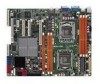
2.2.3 Motherboard layouts Z8NA-D6 2-6 Chapter 2: Hardware information - Asus Z8NA-D6 | User Guide - Page 27
Z8NA-D6C ASUS Z8NA-D6 Series 2-7 - Asus Z8NA-D6 | User Guide - Page 28
1. Clear RTC RAM (CLRTC1) 2. VGA controller setting (3-pin VGA_SW1)) 3. CPU Fan and Chassis Fan control setting (3-pin CPUFAN_SEL1, CHAFAN_SEL1) 4. LAN controller setting (3-pin LAN_SW1, LAN_SW2) 5. Intel® ICH10R SATA port S/W RAID setting (3-pin RAID_SEL1) (Z8NA-D6 model only) 6. iBTN - Asus Z8NA-D6 | User Guide - Page 29
CPU, Power Supply SMBus connector (5-pin PSUSMB1) 12. ATX power connectors (24-pin ATXPWR1, 8-pin ATX12V1) 13. System panel connector (20-1 pin PANEL1) 14. Auxiliary panel connector (20-2 pin AUX_PANEL1) Page 2-30 2-30 2-31 2-32 2-32 2-33 2-33 2-34 2-34 2-35 2-35 2-36 2-37 2-38 ASUS Z8NA-D6 - Asus Z8NA-D6 | User Guide - Page 30
CPU) The motherboard comes with dual surface mount LGA 1366 Socket designed for the Intel® Xeon 5500 series CPU in the Land Grid Array (LGA) package. • Upon purchase of the motherboard the PnP cap/socket contacts/motherboard components. ASUS shoulders the repair cost only if the damage is - Asus Z8NA-D6 | User Guide - Page 31
unless you are installing a CPU. Retention tab A B Load lever 3. Lift the load lever in the direction of the arrow to a 135º angle. 4. Lift the load plate with your thumb and forefinger to a 100º angle. Load plate 4 3 5. Remove the PnP cap from the CPU socket. PnP cap ASUS Z8NA-D6 Series 2-11 - Asus Z8NA-D6 | User Guide - Page 32
notch Alignment key 7. Apply some Thermal Interface Material to the exposed area of the CPU that the heatsink will be in contact with, ensuring that it is spread in an even thin layer. Some heatsinks come with pre-applied Thermal Interface Material. If so, skip this step. Gold triangle mark DO - Asus Z8NA-D6 | User Guide - Page 33
the heatsink on top of the installed CPU, ensuring that the screw holes are matched with the heatsink standoffs. 2. Use a Phillips screwdriver to tighten the four heatsink screws in a diagonal sequence. Ensure that the heatsink is not skewed or tilted, otherwise the CPU will overheat. ASUS Z8NA-D6 - Asus Z8NA-D6 | User Guide - Page 34
to the 4‑pin connector labeled CPU_FAN1 or CPU_FAN2 depending on the CPU socket you install. 3. ���R��e�p�e��a�t�s�t�e�p��s�1��t�o��3��to��i�n�s�t�a�l�l �th��e��o�th��e�r�h��e�a�t�s�in��k�i�f�y�o��u��h�a�v�e��i�n�s�t�a�l�le�d��a��s�e��c�o�n�d� CPU, then connect the fan cable to the other 4‑pin - Asus Z8NA-D6 | User Guide - Page 35
2.4 System memory 2.4.1 Overview The motherboard comes with six (6) Double Data Rate 3 (DDR3) Dual Inline Memory Modules (DIMM) sockets. A DDR3 module for better performance with less power consumption. The figure illustrates the location of the DDR3 DIMM sockets: ASUS Z8NA-D6 Series 2-15 - Asus Z8NA-D6 | User Guide - Page 36
same CAS latency. For optimum compatibility, it is recommended that you obtain memory modules from the same vendor. Memory population table CPU 1 Configuration DIMM_A1 1 DIMMs 2 DIMMs 3 DIMMs CPU 2 Configuration DIMM_D1 1 DIMMs 2 DIMMs 3 DIMMs DIMM_B1 -- DIMM_E1 -- DIMM_C1 --- DIMM_F1 --- 2-16 - Asus Z8NA-D6 | User Guide - Page 37
press the retaining clips outward to unlock the DIMM. 2 DDR3 DIMM notch Support the DIMM lightly with 1 1 your fingers when pressing the retaining clips. The DIMM might get damaged when it flips out with extra force. 2. Remove the DIMM from the socket. ASUS Z8NA-D6 Series 2-17 - Asus Z8NA-D6 | User Guide - Page 38
settings, if any. See Chapter 4 for information on BIOS setup. 2. Assign an IRQ to the card. Refer to the tables on the next page. 3. Install the software drivers for the expansion card. When using PCI cards on shared slots, ensure that the drivers support "Share IRQ" or that the cards do not need - Asus Z8NA-D6 | User Guide - Page 39
Mouse Port 13 8 Numeric Data Processor 14* 9 Primary IDE Channel 15* 10 Secondary IDE Channel * These IRQs are usually available for ISA or PCI devices. ASUS Z8NA-D6 Series 2-19 - Asus Z8NA-D6 | User Guide - Page 40
PCI slot The PCI slot supports cards such as a LAN card, USB card, and other cards that comply with PCI 2.3 specifications. 2.5.8 PIKE slot (Z8NA-D6 model only) The PIKE slot allows you to choose and change your preferred SAS solution easily. Install an optional ASUS PIKE RAID card based on your - Asus Z8NA-D6 | User Guide - Page 41
ASUS RAID card on your motherboard. 1. Locate the PIKE RAID card slot on the motherboard. 2. Align the golden fingers of the RAID card with the PIKE RAID card slot. 3. Insert the RAID card into the PIKE RAID card slot. Ensure that it is completely seated on the PIKE RAID card slot. ASUS Z8NA-D6 - Asus Z8NA-D6 | User Guide - Page 42
using PIKE 1078 functions. 2.5.11 Installing ASMB4 management board (Z8NA-D6 model only) Follow the steps below to install an optional ASMB4 management board on your motherboard. 1. Locate the BMC_FW header on the motherboard. 2. Orient and press the ASMB4 management card in place. 2-22 Chapter - Asus Z8NA-D6 | User Guide - Page 43
thermal sensor cable to the connector on your motherboard. 1. Locate the TR1 or TR2 connector on the motherboard. 2. Connect the thermal sensor cable to the connector. 3. Place the other end of the thermal sensor cable to the device you would like to monitor temperature. ASUS Z8NA-D6 Series 2-23 - Asus Z8NA-D6 | User Guide - Page 44
about 5-10 seconds, then move the cap back to pins 1-2. 3. Plug the power cord and turn ON the computer. 4. Hold down the key during the boot process and enter BIOS setup to re-enter data. Except when clearing the RTC RAM, never remove the cap on CLRTC jumper default position. Removing the cap - Asus Z8NA-D6 | User Guide - Page 45
, CHAFAN_SEL1) These jumpers allow you to switch for fan pin selection. The CPUFAN_SEL1 jumper is for the CPU fans control and the CHAFAN_SEL1 jumper is for the front fans and rear fans control. Set to pins and the fan you installed will always run at full speed. ASUS Z8NA-D6 Series 2-25 - Asus Z8NA-D6 | User Guide - Page 46
setting (3-pin RAID_SEL1) (Z8NA-D6 model only) This jumper allows you to select the Serial ATA RAID configuration utility to use when you create disk arrays. Place the jumper caps on pins 1-2 if you want to use the LSI Logic Embedded SATA RAID Setup Utility (default); otherwise, place the jumper - Asus Z8NA-D6 | User Guide - Page 47
slot and install an optional ASUS PIKE RAID card. 7. DDR3 voltage control setting (4-pin LVDDR3_SEL1; LVDDR3_SEL2) These jumpers allow you to adjust the DIMM voltage. Set to pins 1-2 to select 1.5V BIOS control, pins 2-3 to select 1.2V Force or 3-4 to select 1.35V Force. ASUS Z8NA-D6 Series 2-27 - Asus Z8NA-D6 | User Guide - Page 48
recovery setting (3-pin RECOVERY1) This jumper allows you to quickly update or recover the BIOS settings when it becomes corrupted. To update the BIOS: 1. Prepare a USB flash disk that contains the original or latest BIOS for the motherboard (XXXXXX.ROM) and the AFUDOS.EXE utility. 2. Set the jumper - Asus Z8NA-D6 | User Guide - Page 49
BLINKING Data activity Speed LED Status Description OFF 10 Mbps connection ORANGE 100 Mbps connection GREEN 1 Gbps connection ACT/LINK SPEED LED LED LAN port ASUS Z8NA-D6 Series 2-29 - Asus Z8NA-D6 | User Guide - Page 50
, SATA6; Black) Supported by the Intel® ICH10R chipset, these connectors are for the Serial ATA signal cables for Serial ATA hard disk drives that allows up to 3Gb/s of data transfer rate. If you installed Serial ATA hard disk drives, you can create a RAID 0, RAID 1, RAID 10, or RAID 5 configuration - Asus Z8NA-D6 | User Guide - Page 51
that supports both Serial Attached SCSI (SAS) and Serial ATA (SATA). Each connector supports one device. • These connectors function only when you install a PIKE RAID card. • Connect the SAS hard disk drives to SAS connectors 1-4 (red) when installing a 4-port PIKE RAID card. ASUS Z8NA-D6 Series - Asus Z8NA-D6 | User Guide - Page 52
at the back of the system chassis. These USB connectors comply with USB 2.0 specification that supports up to 480 Mbps connection speed. 5. Serial port connector (10-1 pin COM2) This connector is for a serial (COM) port. Connect the serial port module cable to this connector, then install the - Asus Z8NA-D6 | User Guide - Page 53
. • DO NOT forget to connect the fan cables to the fan connectors. Insufficient air flow inside the system may damage the motherboard components. • These are not jumpers! DO NOT place jumper caps on the fan connectors! • All fans feature the ASUS Smart Fan technology. ASUS Z8NA-D6 Series 2-33 - Asus Z8NA-D6 | User Guide - Page 54
connectors (8-1 pin SGPIO2/3) (Z8NA-D6 model only) These connector is used for the SAS chip SGPIO interface that controls the LED pattern generation, device information and general purpose data. These connectors functions only when you install an ASUS PIKE SAS RAID card. 2-34 Chapter 2: Hardware - Asus Z8NA-D6 | User Guide - Page 55
10. BMC header (BMC_FW1) (Z8NA-D6 model only) The BMC connector on the motherboard supports an ASUS® Server Management Board 4 Series (ASMB4). 11. Power Supply SMBus connector (5-pin PSUSMB1) This connector allows you to connect SMBus (System Management Bus) to the power supply unit to read PSU - Asus Z8NA-D6 | User Guide - Page 56
SSI & ATX power supply plugs. The power supply plugs are designed to fit these connectors in only one orientation. Find the proper orientation and push down firmly until the connectors completely fit. • DO NOT forget to connect the 24+8-pin power plugs; otherwise, the system will not boot up. • Use - Asus Z8NA-D6 | User Guide - Page 57
on the BIOS settings. Pressing the power switch for more than four seconds while the system is ON turns the system OFF. 6. Reset button (2-pin RESET) This 2-pin connector is for the chassis-mounted reset button for system reboot without turning off the system power. ASUS Z8NA-D6 Series 2-37 - Asus Z8NA-D6 | User Guide - Page 58
14. Auxiliary panel connector (20-pin AUX_PANEL1) This connector is for additional front panel features including front panel SMB, locator LED and switch, chassis intrusion, and LAN LEDs. 1. Front panel SMB (6-1 pin FPSMB) These leads connect the front panel SMBus cable. 2. LAN activity LED (2-pin - Asus Z8NA-D6 | User Guide - Page 59
This chapter describes the power up Powerin3g up sequence, and ways of shutting down the system. - Asus Z8NA-D6 | User Guide - Page 60
Chapter summary 3 3.1 Starting up for the first time 3-3 3.2 Turning off the computer 3-4 ASUS Z8NA-D6 Series - Asus Z8NA-D6 | User Guide - Page 61
seconds from the time you turned on the power, the system may have failed a power-on test. Check the jumper settings and connections or call your retailer for assistance. 7. At power on, hold down the key to enter the BIOS Setup. Follow the instructions in Chapter 4. ASUS Z8NA-D6 Series 3-3 - Asus Z8NA-D6 | User Guide - Page 62
3.2 Powering off the computer 3.2.1 Using the OS shut down function If you are using Windows® 2000/2003 Server: 1. Click Start then click Ensure that the Planned check box is checked. 5. Select shutdown from the list box. 6. If necessary, key in comments. 7. Click OK. 3-4 Chapter 3: Powering up - Asus Z8NA-D6 | User Guide - Page 63
This chapter tells how to change the system settings through the BIOS Setup BIOS se4tup menus. Detailed descriptions of the BIOS parameters are also provided. - Asus Z8NA-D6 | User Guide - Page 64
Chapter summary 4 4.1 Managing and updating your BIOS 4-1 4.2 BIOS setup program 4-7 4.3 Main menu 4-10 4.4 Advanced menu 4-17 4.5 Server menu 4-34 4.6 Boot menu 4-36 4.7 Exit menu 4-40 ASUS Z8NA-D6 Series - Asus Z8NA-D6 | User Guide - Page 65
during the updating process. Copying the current BIOS To copy the current BIOS file using the AFUDOS utility: The succeeding BIOS screens are for reference only. The actual BIOS screen displays may not be the same as shown. 1. Copy the AFUDOS utility (afudos.exe) from the motherboard support CD to - Asus Z8NA-D6 | User Guide - Page 66
DOS prompt after copying the current BIOS file. Updating the BIOS file To update the BIOS file using the AFUDOS utility: 1. Visit the ASUS website at www.asus.com and download the latest BIOS file for the motherboard. Save the BIOS file to a bootable�U��S��B��fl�a�s�h��d�i�s�k��d�r�iv��e��. Write - Asus Z8NA-D6 | User Guide - Page 67
Megatrends, Inc. All rights reserved. WARNING!! Do not turn off power during flash BIOS Reading file ....... done Reading flash ...... done Advance Check ...... Erasing flash ...... done Writing flash ...... done Verifying flash .... done Please restart your computer A:\> ASUS Z8NA-D6 Series 4-5 - Asus Z8NA-D6 | User Guide - Page 68
finished. DO NOT shut down or reset the system while recovering the BIOS! Doing so would cause system boot failure! The recovered BIOS may not be the latest BIOS version for this motherboard. Visit the ASUS website at www.asus.com to download the latest BIOS file. 4-6 Chapter 4: BIOS setup - Asus Z8NA-D6 | User Guide - Page 69
the Exit Menu. See section 4.8 Exit Menu. • The BIOS setup screens shown in this section are for reference purposes only, and may not exactly match what you see on your screen. • Visit the ASUS website (www.asus.com) to download the latest BIOS file for this motherboard. ASUS Z8NA-D6 Series 4-7 - Asus Z8NA-D6 | User Guide - Page 70
4.2.1 BIOS menu screen Menu items Menu bar Configuration fields General help Main Advanced BIOS SETUP UTILITY Server Boot Exit System Time [13:44:30] System Date Use [ENTER], [TAB] or [SHIFT-TAB] to select a field. Use [+] or [-] to configure system Date. ←→ Select Screen ↑↓ Select - Asus Z8NA-D6 | User Guide - Page 71
items that do not fit on the screen. Press the Up/Down arrow keys or / keys to display the other items on the screen. 4.2.9 General help Pop-up window Scroll bar At the top right corner of the menu screen is a brief description of the selected item. ASUS Z8NA-D6 Series 4-9 - Asus Z8NA-D6 | User Guide - Page 72
When you enter the BIOS Setup program, the Main menu screen appears, giving you an overview of the basic system information. Refer to section 4.2.1 BIOS menu screen for information on the menu screen items and how to navigate through them. Main Advanced BIOS SETUP UTILITY Server Boot Exit System - Asus Z8NA-D6 | User Guide - Page 73
then press if you wish to configure the item. Main BIOS SETUP UTILITY SATA 1 Device :Hard Disk Vendor :xxxxxxxxx Size :xx.xGB LBA Mode :Supported Block Mode SWDMA0] [SWDMA1] [SWDMA2] [MWDMA0] [MWDMA1] [MWDMA2] [UDMA0] [UDMA1] [UDMA2] [UDMA3] [UDMA4] [UDMA5] ASUS Z8NA-D6 Series 4-11 - Asus Z8NA-D6 | User Guide - Page 74
SMART Monitoring [Auto] Sets the Smart Monitoring, Analysis, and Reporting Technology. Configuration options: [Auto] [Disabled] [Enabled] 32Bit Data Transfer [Enabled] Enables or disables 32-bit data transfer. Configuration options: [Disabled] [Enabled] 4-12 Chapter 4: BIOS setup - Asus Z8NA-D6 | User Guide - Page 75
then press if you wish to configure the item. Main BIOS SETUP UTILITY IDE Configuration SATA Configuration [Enhanced] Configure SATA as [IDE] Hard Disk Write Protect [Disabled] IDE Detect Time Out (Sec) [35] Options Disabled Compatible Enhanced ←→ Select Screen ↑↓ Select Item - Asus Z8NA-D6 | User Guide - Page 76
BIOS SETUP UTILITY AHCI Settings AHCI CD/DVD Boot Time out [35] SATA Port1 [Not Detected] SATA Port2 [Not Detected] SATA Port3 [Not Detected] SATA Port4 [Not Detected] SATA Port5 [Not Detected] SATA Port6 [Not Detected] Some SATA CD/DVD in AHCI mode need to wait ready longer. ←→ Select Screen - Asus Z8NA-D6 | User Guide - Page 77
system memory. System Memory Information Displays system memory information. Main System Memory Information CPU1 Memory Information CPU2 Memory Information BIOS SETUP UTILITY CPU1/2 Memory Configuration Allows you to check information of installed memory (3 DIMMs per CPU). ASUS Z8NA-D6 Series - Asus Z8NA-D6 | User Guide - Page 78
CPU1/2 Memory Configuration Displays the auto-detected memory specification. Main BIOS SETUP UTILITY CPU1 Memory Configuration Speed DDR3 1066 DIMM_A1 DIMM_B1 DIMM_C1 1024 MB, 1R, 1066, 0.254ºC/0.00ºF N/A N/A 4-16 Chapter 4: BIOS setup - Asus Z8NA-D6 | User Guide - Page 79
BIOS SETUP UTILITY Boot Exit CPU Configuration Chipset Configuration Legacy Device Configuration USB Configuration PCIPnP Configuration Power On Configuration Event Log Configuration Hardware Monitor PCI Exppress Configuration ACPI Configuration Configure CPU. ←→ Select Screen ↑↓ Select Item Enter - Asus Z8NA-D6 | User Guide - Page 80
items. Advanced BIOS SETUP UTILITY Execute-Disable Bit Capability [Enabled] Intel(R) HT Technology [Enabled] Active Processor Cores [All] A20M CPU Core Clock and the FSB Frequency. Note:If an invalid ratio is set in CMOS then actual and setpoint values may differ. +F1 F10 ESC Select Screen - Asus Z8NA-D6 | User Guide - Page 81
Technology allows the CPU to save more power under idle mode. Enable this item only when you install a C-State Technology-supported CPU. Configuration options: [Disabled] [Enabled] The following items appear only when you set the Intel(R) C-STATE Tech item to [Enabled]. ASUS Z8NA-D6 Series 4-19 - Asus Z8NA-D6 | User Guide - Page 82
to [Auto] for BIOS to automatically detect the C-State mode supported by your CPU. Configuration options: [Auto ] [C1] [C3] [C6] [C7] C1 Auto Demotion [Enabled] When this item is enabled, the CPU item is enabled, the CPU will conditionally demote C6/ - Asus Z8NA-D6 | User Guide - Page 83
Item Enter Go to Sub Screen F1 General Help F10 Save and Exit ESC Exit v02.61 (C)Copyright 1985-2008, American Megatrends, Inc. CPU Bridge Configuration Advanced BIOS SETUP UTILITY CPU Bridge Chipset Configuration CPU REeVvIiSsIiOoNn :B0 Current CSI Frequency :65.480606GT Current Memory - Asus Z8NA-D6 | User Guide - Page 84
Configuration options: [Disabled] [Enabled] Memory Frequency [Auto] You may allow the system to detect DDR3 memory frequency via SPD or designate a specific frequency. Configuration options: [Auto] ] [Enabled] NUMA Aware [Auto] Configuration options: [Disabled] [Auto] 4-22 Chapter 4: BIOS setup - Asus Z8NA-D6 | User Guide - Page 85
[Disabled] Crystal Beach / DMA configuration. ←→ Select Screen ↑↓ Select Item +- Change Option F1 General Help F10 Save and Exit ESC Exit V02.61 (C)Copyright 1985-2008, American Megatrends, Inc. Crystal Beach / DMA [Disabled] Configuation options: [Disabled] [Enabled] ASUS Z8NA-D6 Series 4-23 - Asus Z8NA-D6 | User Guide - Page 86
South Bridge Configuration Advanced BIOS SETUP UTILITY CPU Bridge Chipset Configuration USB Functions USB Port Configure USB 2.0 Controller HDA Controller [5 USB Ports] [8+4 USB Ports] [Enabled] [Enabled] SLP_S4# Min. Assertion Width [1 to 2 seconds] Options - Asus Z8NA-D6 | User Guide - Page 87
Serial Port2 Address BIOS SETUP UTILITY [Enabled] [3F8/IRQ4] [2F8/IRQ3] Allows BIOS to Enable or Disable Floppy Controller. +F1 F10 ESC Select Screen Select Item Change Option Port2 base address. Configuration options: [Disabled] [2F8/IRQ3] [3E8/IRQ4] [2E8/IRQ3] ASUS Z8NA-D6 Series 4-25 - Asus Z8NA-D6 | User Guide - Page 88
13.4 USB Devices Enabled : None Legacy USB Support USB 2.0 Controller Mode BIOS EHCI Hand-Off [Enabled] [HiSpeed] [Enabled] Enables support for legacy USB. AUTO option disables legacy support if no USB devices are connected. ←→ Select Screen ↑↓ Select Item +- Change Option F1 General - Asus Z8NA-D6 | User Guide - Page 89
field values can cause the system to malfunction. Advanced BIOS SETUP UTILITY Advanced PCI/PnP Settings WARNING: Setting wrong values in ] [High] Onboard LAN1/2 Boot [PXE] Allows you to configure the onboard LAN1/2 boot mode. Configuration: [Disabled] [PXE] [iSCSI] ASUS Z8NA-D6 Series 4-27 - Asus Z8NA-D6 | User Guide - Page 90
BIOS SETUP UTILITY APM Configuration Restore on AC Power Loss [Last State] Resume On Ring [Disabled] Resume On PME#(Wake On LAN) [Disabled] Resume On RTC Alarm [Disabled] Options Power Off Power On Last State ←→ Select Screen Use the , or key to select a - Asus Z8NA-D6 | User Guide - Page 91
Voltage VBAT Voltage [ 1.206 V] [ 1.203 V] [ 1.094 V] [12.456 V] [ 5.196 V] [ 3.240 V] [ 5.132 V] [ 3.228 V] [ 3.132 V] +F1 F10 ESC Select Screen Select Item Change Option General Help Save and Exit Exit v02.61 (C)Copyright 1985-2008, American Megatrends, Inc. ASUS Z8NA-D6 Series 4-29 - Asus Z8NA-D6 | User Guide - Page 92
of CPU fans, front fans, and rear fans in rotations per minute (RPM). If the fan is not connected to the motherboard, the field shows [N/A]. Fan Speed Control [Generic Mode] Allows you to configure the ASUS Smart . Select [Ignored] if you do not want to detect this item. 4-30 Chapter 4: BIOS setup - Asus Z8NA-D6 | User Guide - Page 93
L1 link power states. Configuration options: [Disabled] [Enabled] 4.4.10 ACPI Configuration Advanced ACPI Settings BIOS SETUP UTILITY Advanced Screen ↑↓ Select Item +- Change Option F1 General Help F10 Save and Exit ESC Exit v02.61 (C)Copyright 1985-2008, American Megatrends, Inc. ASUS Z8NA-D6 - Asus Z8NA-D6 | User Guide - Page 94
BIOS SETUP UTILITY Advanced ACPI Configuration ACPI 2.0 Support ACPI APIC support BIOS-->AML ACPI table Headless mode [Enabled] [Enabled] [Enabled] [Disabled] Add additional tables as per ACPI 2.0 specifications. ACPI 2.0 Support [Enabled] Specifies the Advanced Configuration and Power - Asus Z8NA-D6 | User Guide - Page 95
BIOS SETUP UTILITY General WHEA Configuration WHEA Support [Enabled] Enable or disable Windows Hardware Error Architecture. WHEA Support [Enabled] Allows you to enable or disable the Windows Hardware Error Architecture (WHEA) support.Configuration options: [Disabled] [Enabled] ASUS Z8NA-D6 - Asus Z8NA-D6 | User Guide - Page 96
Server menu Main Advanced Server BIOS SETUP UTILITY Boot Exit Remote Access Configuration Configure Remote Access. ←→ Select Screen ↑↓ Select Item +- . Select an item then press to display the configuration options. Server BIOS SETUP UTILITY Configure Remote Access type and - Asus Z8NA-D6 | User Guide - Page 97
mode after the BIOS Power-On Self-Test (POST). Some operating system may not work when set to [Always]. Configuration options: [Disabled] [Boot Loader] [Always] Terminal Type [VT-UTF8] Allows you to select the target terminal type. Configuration options: [ANSI] [VT100] [VT-UTF8] ASUS Z8NA-D6 Series - Asus Z8NA-D6 | User Guide - Page 98
Screen ↑↓ Select Item Enter Go to Sub Screen F1 General Help F10 Save and Exit ESC Exit v02.61 (C)Copyright 1985-2008, American Megatrends, Inc. 4.6.1 Boot Device Priority BIOS SETUP UTILITY Boot Boot Device Priority 1st Boot Device 2nd Boot Device 3rd Boot Device 4th Boot Device 5th Boot - Asus Z8NA-D6 | User Guide - Page 99
4.6.2 Boot Settings Configuration BIOS SETUP UTILITY Boot Boot Settings Configuration Quick Boot Full Screen Logo AddOn ROM Display Mode Bootup Num-Lock Wait For 'F1' If Error Hit 'DEL' Message Display Interrupt 19 Capture [Enabled] [Enabled] [Force BIOS] [On] [Enabled] [Enabled] [ - Asus Z8NA-D6 | User Guide - Page 100
configuration options. BIOS SETUP UTILITY Boot Security Settings Supervisor Password : Not Installed User Password : Not Installed to change password. again to disable password. Change Supervisor Password Change User Password ←→ Select Screen ↑↓ Select Item Enter Change F1 - Asus Z8NA-D6 | User Guide - Page 101
a user password. Password Check [Setup] When set to [Setup], BIOS checks for user password when accessing the Setup utility. When set to [Always], BIOS checks for user password both when accessing Setup and booting the system. Configuration options: [Setup] [Always] ASUS Z8NA-D6 Series 4-39 - Asus Z8NA-D6 | User Guide - Page 102
Advanced Server BIOS SETUP UTILITY Boot Exit Exit Options Exit & Save Changes Exit & Discard Changes Discard Changes Load Setup Defaults Exit system setup after saving the changes. F10 key can be used for this operation. ←→ Select Screen ↑↓ Select Item Enter Go to Sub Screen F1 General Help - Asus Z8NA-D6 | User Guide - Page 103
This chapter provides instructions for setting up, creating, and configuring RAID sets using the available utilities. 5RAID configuration - Asus Z8NA-D6 | User Guide - Page 104
Chapter summary 5 5.1 Setting up RAID 5-3 5.2 LSI Software RAID Configuration Utility 5-5 5.3 Intel® Matrix Storage Manager Option ROM Utility 5-25 ASUS Z8NA-D6 Series - Asus Z8NA-D6 | User Guide - Page 105
of three identical hard disk drives for this setup. If you want to boot the system from a hard disk drive included in a created RAID set, copy first the RAID driver from the support CD to a floppy disk before you install an operating system to the selected hard disk drive. ASUS Z8NA-D6 Series 5-3 - Asus Z8NA-D6 | User Guide - Page 106
connector on the motherboard. 3. Connect a SATA power cable to the power connector on each drive. 5.1.3 Setting the RAID item in BIOS You must set the RAID item in the BIOS Setup before you can create a RAID set from SATA hard disk drives attached to the SATA connectors supported by Intel® ICH10R - Asus Z8NA-D6 | User Guide - Page 107
5.2 LSI Software RAID Configuration Utility (Z8NA-D6 model only) The LSI MegaRAID software RAID configuration utility allows you to create RAID 0, RAID 1, or RAID 10 set(s) from SATA hard disk drives connected to the SATA connectors supported by the motherboard southbridge chip. To enter the LSI - Asus Z8NA-D6 | User Guide - Page 108
, you manually set the virtual drive parameters. Using Easy Configuration To create a RAID set using the Easy Configuration option 1. From the Management Menu, select Configure > Easy Configuration, and then press . LSI Software RAID Configuration Utility Ver A.60 Jul 30, 2008 BIOS Version - Asus Z8NA-D6 | User Guide - Page 109
ENTER-EndArray,F10-Configure,F2-Drive Info,F3-Virtual Drives,F4-HSP • The information of the selected hard disk drive displays at the bottom of the screen. • You need at least two identical hard disk drives when creating a RAID F2-ChIdInfo F3-SlotInfo F10-Configure Esc-Quit ASUS Z8NA-D6 Series 5-7 - Asus Z8NA-D6 | User Guide - Page 110
Virtual Drive sub-menu, and then press . 7. Select the RAID level from the menu, and then press . LSI Software RAID Configuration Utility Ver A.60 Jul 30, 2008 BIOS VVierrtsuailonDrivAe.(0s8).0C9on1f6ig1u3r4e4dR LD RAIEDasy CoSnifizgeuratio#nSt-riApReRsAY SELSEtCrTiIpOSNzMENUStatus - Asus Z8NA-D6 | User Guide - Page 111
0 DNLIN A00-00 Objects Rebuild 1 DNLIN A00-01 Check Consistency Virtual Drive 0 RAID = 1 Size = 77247MB DWC = Off RA = On Accept SPAN = NO Accept This VD Configuration And Go To Next VD Cursor Keys, SPACE-(De)Select F2-ChIdInfo F3-SlotInfo F10-Configure Esc-Quit ASUS Z8NA-D6 Series 5-9 - Asus Z8NA-D6 | User Guide - Page 112
Configuration option 1. From the Management Menu, select Configure > New Configuration, and then press . LSI Software RAID Configuration Utility Ver A.60 Jul 30, 2008 BIOS Version A.08.09161344R Configuration Menu Easy Configuration Management MNeenwu Configuration Configure View/Add - Asus Z8NA-D6 | User Guide - Page 113
(MDBr)i:ve770247 RAID = 1 Size = 77247MB DWC = Off RA = On Accept SPAN = NO Enter VD Size (MB): Use Cursor Keys to Navigate Between Items And Press Enter To Select An Option 5. Follow step 8 to 12 of the previous section: Using Easy Configuration to create the RAID set. ASUS Z8NA-D6 Series - Asus Z8NA-D6 | User Guide - Page 114
# 2 DISK 77247MB HDS728080PLA380 PF20A60A SPACE-Sel,ENTER-EndArray,F10-Configure,F2-Drive Info,F3-Virtual Drives,F4-HSP The information of the selected hard disk drive displays at the bottom of the screen. 3. Follow step 3 to 12 of section 5.2.1 Creating a RAID set: Using Easy Configuration to add - Asus Z8NA-D6 | User Guide - Page 115
BIOS Version A.08.09161344R Virtual Drive(s) Configured Management Menu LD RAID Size #Stripes StripSz Status Configure Initialize 0 1 151634MB 2 64 KB ONLINE Objects Rebuild Check Consistency Virtual Drives Virtual Drive 0 Select VD SPACE-(De)Select, F10-Initialize ASUS Z8NA-D6 Series - Asus Z8NA-D6 | User Guide - Page 116
all data on the drive. 4. A progress bar appears on screen. If desired, press to abort initialization. When initialization is completed, press . LSI Software RAID Configuration Utility Ver A.60 Jul 30, 2008 BIOS Version A.08.09161344R Virtual Drive(s) Configured Management Menu LD - Asus Z8NA-D6 | User Guide - Page 117
Utility Ver A.60 Jul 30, 2008 BIOS Version A.08.09161344R Vitual Drive(1) Virtual Drive 0 Objects Management MAednaupter Configure Virtual Drive Initialize Physical Drive Objects Rebuild Check Consistency Select VD Press ENTER To Select A VD, To Delete A VD ASUS Z8NA-D6 Series 5-15 - Asus Z8NA-D6 | User Guide - Page 118
View/Update Parameters Initilize VD Use Cursor Keys To Navigate Between Items And Press Enter To Select An Option 4. When prompted, press the to select Yes from the Initialize? dialog box, and then press . LSI Software RAID Configuration Utility Ver A.60 Jul 30, 2008 BIOS Version - Asus Z8NA-D6 | User Guide - Page 119
manually rebuild failed hard disk drives using the Rebuild command in the Management Menu. To rebuild a failed hard disk drive 1. From the Management Menu, select Rebuild, and then press . LSI Software RAID Configuration Utility Ver A.60 Jul 30, 2008 BIOS Drives ASUS Z8NA-D6 Series 5-17 - Asus Z8NA-D6 | User Guide - Page 120
3. After selecting the drive to rebuild, press . When prompted, press to rebuild the drive. LSI Software RAID Configuration Utility Ver A.60 Jul 30, 2008 BIOS Version A.08.09161344R REBUILD - PHYSICAL DRIVES SELECTION MENU Management Menu PORT # Configure Initialize 0 ONLIN A00-00 - Asus Z8NA-D6 | User Guide - Page 121
BIOS Version A.08.09161344R Virtual Drive(s) Configured Management Menu LD RAID Size #Stripes StripSz Status Configure 0 10 154494MB 4 64 KB ONLINE Initialize Objects Rebuild Check Consistency Virtual Drives Virtual Drive 0 Select VD SPACE-(De)Select, F10-Check Consistency ASUS Z8NA-D6 - Asus Z8NA-D6 | User Guide - Page 122
-(De)Select, F10-Check Consistency A progress bar appears on screen. LSI Software RAID Configuration Utility Ver A.60 Jul 30, 2008 BIOS Version A.08.09161344R Virtual Drive(s) Configured Management Menu LD RAID Size #Stripes StripSz Configure Initialize 0 1C0C Un1d5e4r49P4rMoBcess 4 64 KB - Asus Z8NA-D6 | User Guide - Page 123
drive you want to check, and then press . 3. Select Check Consistency from the pop-up menu, and then press . 4. When prompted, use the arrow keys to select Yes from the dialog box to check the drive. 5. When checking is complete, press any key to continue. ASUS Z8NA-D6 Series 5-21 - Asus Z8NA-D6 | User Guide - Page 124
Select Boot Drive Rebuild Check Consistency Clear Existing Configuration Use Cursor Keys To Navigate Between Items And Press Enter To Select ? dialog box, and then press . LSI Software RAID Configuration Utility Ver A.60 Jul 30, 2008 BIOS Version A.08.09161344R Configuration Menu Easy - Asus Z8NA-D6 | User Guide - Page 125
Configuration Initialize Clear Configuration Objects Select Boot Drive Rebuild Check Consistency Select A Boot VD Use Cursor Keys To Navigate Between Items And Press Enter To Select An Option 3. The virtual drive is selected as boot drive. Press any key to continue. ASUS Z8NA-D6 Series 5-23 - Asus Z8NA-D6 | User Guide - Page 126
5.2.8 Enabling WriteCache You may manually enable the RAID controller's WriteCache option after creating a RAID set to improve the data transmission performance. When you enable WriteCache, you may lose data when a power interruption occurs while transmitting or exchanging data among the drives. The - Asus Z8NA-D6 | User Guide - Page 127
[ESC]-Exit [ENTER]-Select Menu The navigation keys at the bottom of the screen allow you to move through the menus and select the menu options. The RAID BIOS setup screens shown in this section are for reference only and may not exactly match the items on your screen. ASUS Z8NA-D6 Series 5-25 - Asus Z8NA-D6 | User Guide - Page 128
, press the up/down arrow key to select a RAID level to create, and then press . 4. When the Disks item is selected, press to select the hard disk drives you want to include in the RAID set. The SELECT DISKS screen appears. Port Drive Model 0 ST3160812AS 1 ST3160812AS 2 ST3160812AS - Asus Z8NA-D6 | User Guide - Page 129
Name: RAID Level: Disks: Strip Size: Capacity: Sync: Volume0 RAID0(Stripe) Select Disks 128KB 0.0 GB N/A Create Volume [ HELP ] Enter a unique volume name that has no special characters and is 16 characters or less. [↑↓]Change [TAB]-Next [ESC]-Previous Menu [ENTER]-Select ASUS Z8NA-D6 Series - Asus Z8NA-D6 | User Guide - Page 130
set and press . 3. When the RAID Level item is selected, press the up/down arrow key to select Recovery, and then press . 4. When the Disks item is selected, press to select the hard disk drives you want to include in the recovery set. The SELECT DISKS screen appears. Port - Asus Z8NA-D6 | User Guide - Page 131
delete a RAID set. To delete a RAID set 1. From the utility main menu, select 2. Delete RAID Volume and press . The following screen appears. Press to delete the RAID set and return to the utility main menu, or press to return to the DELETE VOLUME menu. ASUS Z8NA-D6 Series 5-29 - Asus Z8NA-D6 | User Guide - Page 132
disk drive 1. From the utility main menu, select 3. Reset Disks to Non-RAID and press . The following screen appears. [ RESET RAID DATA ] Resetting RAID disk will remove its RAID structures and revert it to a non-RAID disk. WARNING: Resetting a disk causes all data on the disk to be lost - Asus Z8NA-D6 | User Guide - Page 133
Options and press . The following screen appears. Intel(R) ENTER]-Done 3. Use the up/down arrow key to select a drive, and then press to select. A small triangle marks the selected drive. Press after completing your selection and return to the utility main menu. ASUS Z8NA-D6 - Asus Z8NA-D6 | User Guide - Page 134
failed, the system displays the status of the RAID volume as "Degraded" during POST. You can rebuild the RAID array with other installed non-RAID disks. To rebuild the RAID with other non-RAID disk: 1. At the prompt, press + to enter the Intel Matrix Storage Manager option ROM utility - Asus Z8NA-D6 | User Guide - Page 135
and install a new SATA hard disk of the same specification into the same SATA Port. Select a destination disk with the same size as the original hard disk. 2. Reboot the system and then follow the steps in section Rebuilding the RAID with other non-RAID disk on page 5-32. ASUS Z8NA-D6 Series 5-33 - Asus Z8NA-D6 | User Guide - Page 136
the boot priority sequence in the BIOS for your RAID arrays when creating multi-RAID using the Intel® Matrix Storage Manager. To set the boot array in the BIOS: Set at least one of the arrays bootable to boot from the hard disk. 1. Reboot the system and press to enter the BIOS setup utility - Asus Z8NA-D6 | User Guide - Page 137
This chapter provides instructions for installing the necessary drivers for different system components. 6Driver installation - Asus Z8NA-D6 | User Guide - Page 138
Chapter summary 6 6.1 RAID driver installation 6-3 6.2 Intel chipset device software installation 6-15 6.3 LAN driver installation 6-19 6.4 Display driver installation 6-23 6.5 Management application and utilities installation 6-26 ASUS Z8NA-D6 Series - Asus Z8NA-D6 | User Guide - Page 139
the Makedisk application in the support DVD). To create a RAID driver disk in DOS environment: 1. Place the motherboard support DVD in the optical drive. 2. Restart the computer, then enter the BIOS Setup. 3. Select the optical drive as the first boot priority to boot from the support DVD. Save your - Asus Z8NA-D6 | User Guide - Page 140
ICH10R Intel RAID Driver ICH10R INTEL RAID Driver Windows 32 bit Windows 64 bit Back Exit ICH10R LSI RAID Driver ICH10R LSI RAID Driver Windows XP 32 bit Windows XP 64 bit Windows Server 2003 32 bit Windows bit SLES 10 SP2 32 bit SLES 10 SP2 64 bit Back Exit 6-4 Chapter 6: Driver installation - Asus Z8NA-D6 | User Guide - Page 141
bit SLES 9 SP3 32 bit SLES 9 SP3 64 bit SLES 10 32 bit SLES 10 64 bit FreeBSD 7 32/64 bit Back Exit 6. Locate the RAID driver and place a blank, high-density floppy disk to the floppy disk drive. 7. Press . 8. Follow onscreen instructions to create the driver disk. ASUS Z8NA-D6 6-5 - Asus Z8NA-D6 | User Guide - Page 142
SCSI or RAID driver... 3. The next screen appears. Press to specify an additional device. Windows Setup Setup could not determine the type of one or more mass storage devices installed in your system, or you have chosen to manually specify an adapter. Currently, Setup will load support for the - Asus Z8NA-D6 | User Guide - Page 143
you need from the list, then press . 6. The Windows® Setup loads the RAID controller drivers from the RAID driver disk. When next screen appears, press to continue installation. 7. Setup then proceeds with the OS installation. Follow screen instructions to continue. ASUS Z8NA-D6 6-7 - Asus Z8NA-D6 | User Guide - Page 144
devices installed in the system. 5. Right-click the RAID controller item, then select Properties. 6. Click the Driver tab, then click the Update Driver button. 7. The Upgrade Device Driver Wizard window appears. Click Next. 8. Insert the RAID driver disk you created earlier to the floppy disk drive - Asus Z8NA-D6 | User Guide - Page 145
4. Select fd0 using the key when asked to select the driver disk source. Press to move the cursor to OK, then press . Driver Disk Source You have multiple devices which could serve as sources for a driver disk. Which would you like to use? fd0 scd0 OK Cancel ASUS Z8NA-D6 6-9 - Asus Z8NA-D6 | User Guide - Page 146
installed to the system. 6. When asked if you will load additional RAID controller drivers, select No, then press . More Driver Disks? Do you wish to load any more driver disks? Yes No 7. Follow the onscreen instructions to finish the OS installation. 8. When the installation is completed - Asus Z8NA-D6 | User Guide - Page 147
Type the following commands when using a USB floppy. cat /proc/partitions Write down the Major and Minor number before sdb for later use. mknod /dev/sdb b [major number] [minor number] mkdir /mnt/driver mount /dev/sdb /mnt/driver cd /mnt/driver sh replace_ahci.sh reboot ASUS Z8NA-D6 6-11 - Asus Z8NA-D6 | User Guide - Page 148
Installation--Local APIC Disabled Installation--Safe Settings Rescue System Memory Test Boot Options | F1 Help F2 Language F3 1280 x 1024 F4 DVD F5 Driver 4. Press , then select Yes from the menu. Press . Boot from Hard Disk Installation Installation--ACPI Disabled Installation--Local - Asus Z8NA-D6 | User Guide - Page 149
the driver update medium. Select OK, then press . Please choose the Driver Update medium. fd0: Floppy sr0: CD-ROM, TEAC DV-516E sda: Disk, SEAGATE ST336754SS sdb: Disk, SEAGATE ST336754SS Other device OK Back The drivers for the RAID controller are installed to the system. ASUS Z8NA-D6 - Asus Z8NA-D6 | User Guide - Page 150
to the command-line interface from graphic user interface. 8. Type the following commands when using a Legacy floppy. mkdir /mnt/driver mount /dev/fd0 /mnt/driver cd /mnt/driver sh replace_ahci.sh reboot Type the following commands when using a USB floppy. cat /proc/partitions Write down the Major - Asus Z8NA-D6 | User Guide - Page 151
computer, then log on with Administrator privileges. 2. Insert the motherboard/system support DVD to the optical drive. The support DVD automatically displays the Drivers menu if Autorun is enabled in your computer. 3. Click the item Intel Chipset Device Software from the menu. ASUS Z8NA-D6 6-15 - Asus Z8NA-D6 | User Guide - Page 152
4. The Intel(R) Chipset Device Software window appears. Click Next to start the installation. 5. Select Yes to accept the terms of the License Agreement and continue the process. 6-16 Chapter 6: Driver installation - Asus Z8NA-D6 | User Guide - Page 153
6. Read the Readme File Information and click Next to activate the installation. 7. After completing the installation, click Next to continue. ASUS Z8NA-D6 6-17 - Asus Z8NA-D6 | User Guide - Page 154
8. Click Yes, I want to restart this computer now and click Finish to restart the computer. 6-18 Chapter 6: Driver installation - Asus Z8NA-D6 | User Guide - Page 155
if Autorun is enabled in your computer. If Autorun is NOT enabled in your computer, browse the contents of the support DVD to locate the file AUTORUN.EXE and double-click the AUTORUN.EXE and follow step 4 to run the installation. 3. Click Intel® PRO/1000 Gigabit Adapters Driver. ASUS Z8NA-D6 6-19 - Asus Z8NA-D6 | User Guide - Page 156
4. When the Intel® PRO Network Connections - InstallShield Wizard window appears, click Next to start the installation. 5. Click I accept the terms in the license agreement and then click Next to continue. 6-20 Chapter 6: Driver installation - Asus Z8NA-D6 | User Guide - Page 157
6. Select the programs you want to install and click Next to continue. 7. Click Install to start the installation. ASUS Z8NA-D6 6-21 - Asus Z8NA-D6 | User Guide - Page 158
8. The programs you select are being installed. 9. Click Finish to finish the installation. 6-22 Chapter 6: Driver installation - Asus Z8NA-D6 | User Guide - Page 159
motherboard/system support DVD to the optical drive. The support DVD automatically displays the Drivers menu if Autorun is enabled in your computer. The Drivers menu if Autorun is enabled in your computer. 3. When the ASPEED InstallShield Wizard window appears, click Next to continue. ASUS Z8NA-D6 - Asus Z8NA-D6 | User Guide - Page 160
4. Click Install to start the installation. 5. The system installs the driver automatically. 6-24 Chapter 6: Driver installation - Asus Z8NA-D6 | User Guide - Page 161
6. When the installation completes, click Finish to exit the wizard. 7. Click Yes to restart the computer. ASUS Z8NA-D6 6-25 - Asus Z8NA-D6 | User Guide - Page 162
package contains the drivers, management applications, and utilities that you can install to avail all motherboard features. The contents of the support DVD are subject to change at any time without notice. Visit the ASUS website at www.asus.com for updates. 6.5.1 Running the support DVD Place the - Asus Z8NA-D6 | User Guide - Page 163
disk menu contains items to create the Intel Matrix Storage Manager and LSI Embedded MegaRAID driver disk. 6.5.5 Contact information Click the Contact tab to display the ASUS contact information. You can also find this information on the inside front cover of this user guide. ASUS Z8NA-D6 6-27 - Asus Z8NA-D6 | User Guide - Page 164
6-28 Chapter 6: Driver installation - Asus Z8NA-D6 | User Guide - Page 165
This appendix includes additional Reference informaAtion information that you may refer to when configuring the motherboard. - Asus Z8NA-D6 | User Guide - Page 166
Appendix summary A A.1 Z8NA-D6 block diagram A-3 A.2 Z8NA-D6C block diagram A-4 ASUS Z8NA-D6 Series - Asus Z8NA-D6 | User Guide - Page 167
A.1 Z8NA-D6 block diagram ASUS Z8NA-D6 Series A-3 - Asus Z8NA-D6 | User Guide - Page 168
A.2 Z8NA-D6C block diagram A-4 Appendix A: Reference information
-
 1
1 -
 2
2 -
 3
3 -
 4
4 -
 5
5 -
 6
6 -
 7
7 -
8
-
9
-
10
-
11
-
12
-
13
-
14
-
15
-
16
-
17
-
18
-
19
-
20
-
21
-
22
-
23
-
24
-
25
-
26
-
27
-
28
-
29
-
30
-
31
-
32
-
33
-
34
-
35
-
36
-
37
-
38
-
39
-
40
-
41
-
42
-
43
-
44
-
45
-
46
-
47
-
48
-
49
-
50
-
51
-
52
-
53
-
54
-
55
-
56
-
57
-
58
-
59
-
60
-
61
-
62
-
63
-
64
-
65
-
66
-
67
-
68
-
69
-
70
-
71
-
72
-
73
-
74
-
75
-
76
-
77
-
78
-
79
-
80
-
81
-
82
-
83
-
84
-
85
-
86
-
87
-
88
-
89
-
90
-
91
-
92
-
93
-
94
-
95
-
96
-
97
-
98
-
99
-
100
-
101
-
102
-
103
-
104
-
105
-
106
-
107
-
108
-
109
-
110
-
111
-
112
-
113
-
114
-
115
-
116
-
117
-
118
-
119
-
120
-
121
-
122
-
123
-
124
-
125
-
126
-
127
-
128
-
129
-
130
-
131
-
132
-
133
-
134
-
135
-
136
-
137
-
138
-
139
-
140
-
141
-
142
-
143
-
144
-
145
-
146
-
147
-
148
-
149
-
150
-
151
-
152
-
153
-
154
-
155
-
156
-
157
-
158
-
159
-
160
-
161
-
162
-
163
-
164
-
165
-
166
-
167
-
168
 |
 |

Motherboard
Z8NA-D6 Series
Z8NA-D6
Z8NA-D6C