Asus Z8PE-D12 User Manual
Asus Z8PE-D12 - Motherboard - SSI EEB 3.61 Manual
 |
UPC - 610839170050
View all Asus Z8PE-D12 manuals
Add to My Manuals
Save this manual to your list of manuals |
Asus Z8PE-D12 manual content summary:
- Asus Z8PE-D12 | User Manual - Page 1
Motherboard Z8PE-D12 Series Z8PE-D12X Z8PE-D12 - Asus Z8PE-D12 | User Manual - Page 2
the express written permission of ASUSTeK COMPUTER INC. ("ASUS"). Product warranty or service will not be extended if: (1) the product is BY ASUS. ASUS ASSUMES NO RESPONSIBILITY OR LIABILITY FOR ANY ERRORS OR INACCURACIES THAT MAY APPEAR IN THIS MANUAL, INCLUDING THE PRODUCTS AND SOFTWARE DESCRIBED - Asus Z8PE-D12 | User Manual - Page 3
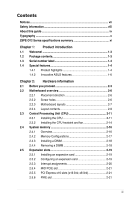
viii About this guide ix Typography x Z8PE-D12 Series specifications summary xi Chapter 1: Product introduction 1.1 Welcome 1-3 1.2 Package contents 1-3 1.3 Serial number label 1-4 1.4 Special features 1-4 1.4.1 Product highlights 1-4 1.4.2 Innovative ASUS features 1-6 Chapter 2: Hardware - Asus Z8PE-D12 | User Manual - Page 4
OS shut down function 3-4 3.2.2 Using the dual function power switch 3-4 Chapter 4: BIOS setup 4.1 Managing and updating your BIOS 4-3 4.1.1 AFUDOS utility 4-3 4.1.2 ASUS CrashFree BIOS 3 utility 4-6 4.2 BIOS setup program 4-7 4.2.1 BIOS menu screen 4-8 4.2.2 Menu bar 4-8 4.2.3 Navigation - Asus Z8PE-D12 | User Manual - Page 5
PCIPnP 4-26 4.4.6 Power On Configuration 4-27 4.4.7 Event Log Configuration 4-28 4.4.8 Hardware Monitor 4-28 4.4.9 PCI Express Configuration 4-30 4.4.10 ACPI Configuration 4-30 4.5 Server menu 4-33 4.5.1 Remote Access Configuration 4-33 4.6 Boot menu 4-35 4.6.1 Boot Device Priority 4-35 - Asus Z8PE-D12 | User Manual - Page 6
6-20 6.4.1 Windows® Server 2003 6-20 6.5 Management applications and utilities installation 6-23 6.5.1 Running the support CD 6-23 6.5.2 Drivers menu 6-23 6.5.3 Utilities menu 6-24 6.5.4 Make disk menu 6-24 6.5.5 Contact information 6-24 Appendix: Reference information A.1 Z8PE-D12 block - Asus Z8PE-D12 | User Manual - Page 7
and used in accordance with manufacturer' s instructions, may cause harmful interference to radio communications. be determined by turning the equipment off and on, the user is encouraged to try to correct the interference by one ASUS REACH website at http://green.asus.com/english/REACH.htm. vii - Asus Z8PE-D12 | User Manual - Page 8
are using, contact your local power company. • If the power supply is broken, do not try to fix it by yourself. Contact a qualified service technician or your retailer. Operation safety • Before installing the motherboard and adding devices on it, carefully read all the manuals that came with the - Asus Z8PE-D12 | User Manual - Page 9
configuring the motherboard. Where to find more information Refer to the following sources for additional information and for product and software updates. 1. ASUS websites The ASUS website provides updated information on ASUS hardware and software products. Refer to the ASUS contact information - Asus Z8PE-D12 | User Manual - Page 10
manual. DANGER/WARNING: Information to prevent injury to yourself when trying to complete a task. CAUTION: Information to prevent damage to the components when trying to complete a task. IMPORTANT: Instructions as shown, then supply the required item or value enclosed in brackets. - Asus Z8PE-D12 | User Manual - Page 11
Z8PE-D12X Z8PE-D12 Processor Support / System Bus 2 * socket 1366 Quad-Core Intel® Xeon® 2 * socket 1366 Quad-Core Intel® Xeon® W5500 Series (130W) Quad-Core Intel® Xeon® W5500 Series (130W) Quad-Core Intel® Xeon® X5500 Series (95W) Quad-Core Intel® Xeon® X5500 Series (95W) Quad-Core Intel - Asus Z8PE-D12 | User Manual - Page 12
300MB/s ports Intel Matrix Storage (for Intel Matrix Storage (for Windows only) Windows only) (Support software RAID 0, (Support software RAID 0, 1, 10 & 5) 1, 10 & 5) LSI® MegaRAID (for Linux/ LSI® MegaRAID (for Linux/ Windows) Windows) (Support software RAID 0, (Support software RAID - Asus Z8PE-D12 | User Manual - Page 13
Port VGA Port 1 1 RJ-45 3 (one for iKVM) 3 (one for iKVM) PS/2 KB/Mouse 1 1 Software ASWM ASWM Out of Band Remote Management Optional ASMB4-iKVM for Optional ASMB4-iKVM for KVM-over-IP support KVM-over-IP support CPU V V Temperature FAN RPM V V Operation temperature: Operation - Asus Z8PE-D12 | User Manual - Page 14
xiv - Asus Z8PE-D12 | User Manual - Page 15
This chapter describes the motherboard introPdruoc1dtuiocnt features and the new technologies it supports. - Asus Z8PE-D12 | User Manual - Page 16
Chapter summary 1 1.1 Welcome 1-3 1.2 Package contents 1-3 1.3 Serial number label 1-4 1.4 Special features 1-4 ASUS Z8PE-D12 Series - Asus Z8PE-D12 | User Manual - Page 17
Pack Standard Bulk Pack Z8PE-D12 series Z8PE-D12 series SATA data cable 6 -- Cables IDE cable 1 -- FDD cable 1 (Z8PE-D12X only) -- Accessories IO shield 1 1 Support CD 1 1 Application CD CA eTrust Anti-virus software CD 1 1 Documentation User Guide 1 1 Packing Qty. 1pcs per - Asus Z8PE-D12 | User Manual - Page 18
problems. Z8PE-D12 xxM0Axxxxxxx Made in China 合格 1.4 Special features 1.4.1 Product highlights Latest processor technology This motherboard supports the latest Intel Xeon 5500 series processors in LGA 1366 package with integrated memory controller to support 3-channel (6 DIMM per CPU) DDR3 memory - Asus Z8PE-D12 | User Manual - Page 19
to 32GB/s. Furthermore, the supply voltage for the memory is reduced from 1.8 V for DDR2 to just 1.5V for DDR3. This voltage reduction limits the power consumption and heat generation of DDR3 which makes it an ideal memory solution. PCIe 2.0 This motherboard supports the latest PCIe 2.0 device for - Asus Z8PE-D12 | User Manual - Page 20
Polymer Capacitors This motherboard uses all high-quality conductive polymer capacitors (5000hrs) onboard for durability, improved lifespan, and enhanced thermal capacity. 1.4.2 Innovative ASUS features ASUS EPU With current trends leaning towards power efficiency, the Z8PE-D12X is equipped with - Asus Z8PE-D12 | User Manual - Page 21
This chapter lists the hardware setup procedures that you have to perform when installing system components. It includes description of the jumpers and connectors on the motherboard. 2 Hardware information - Asus Z8PE-D12 | User Manual - Page 22
Chapter summary 2 2.1 Before you proceed 2-3 2.2 Motherboard overview 2-6 2.3 Central Processing Unit (CPU 2-11 2.4 System memory 2-16 2.5 Expansion slots 2-19 2.6 Jumpers 2-25 2.7 Connectors 2-31 ASUS Z8PE-D12 Series - Asus Z8PE-D12 | User Manual - Page 23
the system is ON, in sleep mode, or in soft-off mode. This is a reminder that you should shut down the system and unplug the power cable before removing or plugging in any motherboard component. The illustration below shows the location of the onboard LED ASUS Z8PE-D12 Series 2-3 - Asus Z8PE-D12 | User Manual - Page 24
warning LEDs light up to indicate that an impending failure of the corresponding CPU. The warning LEDs function only when you install the ASUS ASMB4. 3. DIMM warning LED (ERR_DIMMA1/2; ERR_DIMMB1/2; ERR_DIMMC1/2; ERR_DIMMD1/2; ERR_DIMME1/2; ERR_DIMMF1/2) The DIMM warning LEDs light up to indicate - Asus Z8PE-D12 | User Manual - Page 25
4. BMC LED (BMC_LED1) The green heartbeat LED blinks per second to indicate that the ASMB4 is working normally. The heartbeat LED functions only when you install the ASUS ASMB4. ASUS Z8PE-D12 Series 2-5 - Asus Z8PE-D12 | User Manual - Page 26
EEB 1.1 compliant chassis. Ensure to unplug the chassis power cord before installing or removing the motherboard. Failure to do so can cause you physical injury and damage motherboard components! 2.2.1 Placement direction When installing the motherboard, ensure that you place it into the chassis in - Asus Z8PE-D12 | User Manual - Page 27
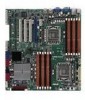
2.2.3 Motherboard layouts Z8PE-D12X ASUS Z8PE-D12 Series 2-7 - Asus Z8PE-D12 | User Manual - Page 28
Z8PE-D12 Z8PE-D12 Intel® 5520 IOH SATA6 SATA5 SATA4 SATA3 SATA2 SATA1 2-8 Chapter 2: Hardware information - Asus Z8PE-D12 | User Manual - Page 29
slot Jumpers 1. Clear RTC RAM (CLRTC1) 2. VGA controller setting (3-pin VGA_SW1)) 3. CPU Fan and Chassis Fan . Force BIOS recovery setting (3-pin RECOVERY1) Rear panel connectors 1. PS/2 mouse port (green) 2. RJ-45 port for iKVM 3. PS 2-31 2-31 2-31 2-31 2-31 ASUS Z8PE-D12 Series 2-9 - Asus Z8PE-D12 | User Manual - Page 30
drive connector (34-1 pin FLOPPY1) (Z8PE-D12X only) 2. Serial ATA connectors (7-pin sensor cable connectors (3-pin TR1, TR2) 8. CPU, front and rear fan connectors (4-pin CPU_FAN1 header (BMC_FW1) 14. Power Supply SMBus connector (5-pin PSUSMB1) 14. ATX power connectors (24-pin ATXPWR1, - Asus Z8PE-D12 | User Manual - Page 31
2.3 Central Processing Unit (CPU) The motherboard comes with dual surface mount LGA 1366 Socket designed for the Intel® Xeon 5500 series CPU in the Land Grid Array (LGA) package. • Upon purchase of the motherboard, ensure that the PnP cap is on the socket and the socket contacts are not bent. - Asus Z8PE-D12 | User Manual - Page 32
(B) until it is released from the retention tab. To prevent damage to the socket pins, do not remove the PnP cap unless you are installing a CPU. Retention tab A B Load lever 3. Lift the load lever in the direction of the arrow to a 135º angle. 4. Lift the load plate with your thumb and - Asus Z8PE-D12 | User Manual - Page 33
off immediately and seek professional medical help. To prevent contaminating the Thermal Interface Material, DO NOT spread the Thermal Interface Material with your finger directly. ASUS Z8PE-D12 Series 2-13 - Asus Z8PE-D12 | User Manual - Page 34
heatsink and fan The Intel Xeon 5500 series processors require a specially designed heatsink to ensure optimum thermal condition and performance. • Ensure to use qualified heatsink assembly only. • Ensure that you have applied the thermal grease to the top of the CPU before installing the heatsink - Asus Z8PE-D12 | User Manual - Page 35
or CPU_FAN2 depending on the CPU socket you install. 3. ���R��e�p�e��a�t�s�t�e�p��s�1��t�o��3��to��i�n�s�t�a�l�l �th��e��o�th��e�r�h��e�a�t�s�in��k�i�f�y�o��u��h�a�v�e��i�n�s�t�a�l�le�d��a��s�e��c�o�n�d� CPU, then connect the fan cable to the other 4‑pin connector. ASUS Z8PE-D12 Series 2-15 - Asus Z8PE-D12 | User Manual - Page 36
2.4 System memory 2.4.1 Overview The motherboard comes with twelve (12) Double Data Rate 3 (DDR3) Dual Inline Memory Modules (DIMM) sockets. A DDR3 module has the same physical dimensions as a DDR2 DIMM but is notched differently to prevent installation on a DDR2 DIMM socket. DDR3 - Asus Z8PE-D12 | User Manual - Page 37
1 DIMMs -- 2 DIMMs -- 3 DIMMs -- 4 DIMMs 6 DIMMs CPU 2 Configuration DIMM_D2 1 DIMMs -- 2 DIMMs -- 3 DIMMs -- 4 DIMMs 6 DIMMs DIMM_A1 DIMM_D1 DIMM_B2 ----- DIMM_E2 ----- DIMM_B1 -- DIMM_E1 -- DIMM_C2 ----- DIMM_F2 ----- DIMM_C1 --- DIMM_F1 --- ASUS Z8PE-D12 Series 2-17 - Asus Z8PE-D12 | User Manual - Page 38
the power supply before adding or removing DIMMs or other system components. Failure to do so can cause severe damage to both the motherboard and into a socket to avoid damaging the DIMM. • The DDR3 DIMM sockets do not support DDR and DDR2 DIMMs. DO NOT install DDR or DDR2 DIMMs to the DDR3 DIMM - Asus Z8PE-D12 | User Manual - Page 39
the software drivers for the expansion card. When using PCI cards on shared slots, ensure that the drivers support "Share IRQ" or that the cards do not need IRQ assignments. Otherwise, conflicts will arise between the two PCI groups, making the system unstable and the card inoperable. ASUS Z8PE-D12 - Asus Z8PE-D12 | User Manual - Page 40
2.5.3 Interrupt assignments Standard Interrupt assignments IRQ Priority Standard function 0 1 System Timer 1 2 Keyboard Controller 2 - Programmable Interrupt 3* 11 Communications Port (COM2) 4* 12 Communications Port (COM1) 5* 13 -- 6 14 Floppy Disk Controller 7* 15 -- 8 - Asus Z8PE-D12 | User Manual - Page 41
great sound quality to complement the robust video power. This slot does not support PCI-E x1 cards. 2.5.5 PCI Express x16 slots (x16 link; x8 link) The onboard PCI Express x16 slots provides one x16 link and three x8 links to Intel 5520 IOH chipset. These slots support VGA cards and various server - Asus Z8PE-D12 | User Manual - Page 42
RAID card Follow the steps below to install an optional ASUS RAID card on your motherboard. 1. Locate the PIKE RAID card slot on the motherboard. 2. Align the golden fingers of the RAID card with the PIKE RAID card slot. 3. Insert the RAID card into the PIKE RAID card slot. Ensure - Asus Z8PE-D12 | User Manual - Page 43
ASMB4 management board Follow the steps below to install an optional ASMB4 management board on your motherboard. 1. Locate the BMC_FW header on the motherboard. 2. Orient and press the ASMB4 management card in place. You need to install I Button before using PIKE 1078 functions. ASUS Z8PE-D12 - Asus Z8PE-D12 | User Manual - Page 44
thermal sensor cable to the connector on your motherboard. 1. Locate the TR1 or TR2 connector on the motherboard. 2. Connect the thermal sensor cable to the Installing the audio card 1. Locate the audio slot on the motherboard. 2. Align the card connector with the slot and press firmly until the card - Asus Z8PE-D12 | User Manual - Page 45
RTC RAM, never remove the cap on CLRTC jumper default position. Removing the cap will cause system boot failure! If the steps above do not help, remove the onboard battery and move the jumper again to clear the CMOS RTC RAM data. After the CMOS clearance, reinstall the battery. ASUS Z8PE-D12 Series - Asus Z8PE-D12 | User Manual - Page 46
and Chassis Fan control setting (3-pin CPUFAN_SEL1, CHAFAN_SEL1) These jumpers allow you to switch for fan pin selection. The CPUFAN_SEL1 jumper is for the CPU fans control and the CHAFAN_SEL1 jumper is for the front fans and rear fans control. Set to pins 1-2 when using 4-pin fans or pins 2-3 when - Asus Z8PE-D12 | User Manual - Page 47
Intel® Intel 82574LGigabit LAN controllers. Set to pins 1-2 to activate the Gigabit LAN feature. 5. IDE control setting (3-pin IDE_SW1) This jumper allows you to enable or disable the IDE connector. Set to pins 1-2 to enable the IDE connector or pins 2-3 disable the IDE connector. ASUS Z8PE-D12 - Asus Z8PE-D12 | User Manual - Page 48
the system unstable. 7. DDR3 voltage control setting (4-pin LVDDR3_SEL1; LVDDR3_SEL2) These jumpers allow you to adjust the DIMM voltage. Set to pins 1-2 to select 1.5V BIOS control, pins 2-3 to select 1.2V Force or 3-4 to select 1.35V Force. 2-28 Chapter 2: Hardware information - Asus Z8PE-D12 | User Manual - Page 49
pins 1-2 if you install a PIKE RAID card to the motherboard and want to use the LSI Logic MPT Setup Utility (default pins 2-3 to create the LSI Mega RAID 5 by supported Intel® ICH10R SATA controller. 9. RAID configuration utility selection (3- Intel® Matrix Storage Manager. ASUS Z8PE-D12 Series 2-29 - Asus Z8PE-D12 | User Manual - Page 50
recovery setting (3-pin RECOVERY1) This jumper allows you to quickly update or recover the BIOS settings when it becomes corrupted. To update the BIOS: 1. Prepare a USB flash disk that contains the original or latest BIOS for the motherboard (XXXXXX.ROM) and the AFUDOS.EXE utility. 2. Set the jumper - Asus Z8PE-D12 | User Manual - Page 51
/2 mouse port (green). This port is for a PS/2 mouse. 2. RJ-45 port for iKVM. This RJ-45 port functions only when you install ASMB4 management card. 3. PS/2 keyboard port (purple). This port is for a PS/2 keyboard. 4. 1 Gbps connection ACT/LINK SPEED LED LED LAN port ASUS Z8PE-D12 Series 2-31 - Asus Z8PE-D12 | User Manual - Page 52
Floppy disk drive connector (34-1 pin FLOPPY1) (Z8PE-D12X only) This connector is for the provided floppy connectors (7-pin SATA1, SATA2, SATA3, SATA4; RED) (7-pin SATA5, SATA6; Black) Supported by the Intel® ICH10R chipset, these connectors are for the Serial ATA signal cables for Serial ATA hard - Asus Z8PE-D12 | User Manual - Page 53
DMA 133/100/66 signal cable has three connectors: a blue connector for the primary IDE connector on the motherboard, a black connector for an Ultra DMA 133/100/66 IDE slave device (optical drive/hard disk drive), ensure that all other device jumpers have the same setting. ASUS Z8PE-D12 Series 2-33 - Asus Z8PE-D12 | User Manual - Page 54
(7-pin SAS5, SAS6, SAS7, SAS8; Blue) This motherboard comes with eight (8) Serial Attached SCSI (SAS) connectors, the next-generation storage technology that supports both Serial Attached SCSI (SAS) and Serial ATA (SATA). Each connector supports one device. • These connectors function only when you - Asus Z8PE-D12 | User Manual - Page 55
that supports up to 480 Mbps connection speed. 7. Thermal sensor cable connectors (3-pin TR1, TR2) These connectors are for temperature monitoring. Connect the thermal sensor cables to these connectors and place the other ends to the devices, which you want to monitor temperature. ASUS Z8PE-D12 - Asus Z8PE-D12 | User Manual - Page 56
support cooling fans of 350 mA-740 mA (8.88 W max.) or a total of 3.15 A-6.66 A (53.28 W max.) at +12V. Connect the fan cables to the fan connectors on the motherboard motherboard components. • These are not jumpers! DO NOT place jumper caps on the fan connectors! • All fans feature the ASUS Smart - Asus Z8PE-D12 | User Manual - Page 57
pin SGPIO1) This connector is used for the SGPIO peripherals for the LSI MegaRAID and Intel Matrix RAID SATA LED. 11. Serial General Purpose Input/Output connectors (8-1 pin SGPIO2/3) These . These connectors functions only when you install an ASUS PIKE SAS RAID card. ASUS Z8PE-D12 Series 2-37 - Asus Z8PE-D12 | User Manual - Page 58
this connector, then install the module to a slot opening at the back of the system chassis. 13. BMC header (BMC_FW1) The BMC connector on the motherboard supports an ASUS® Server Management Board 4 Series (ASMB4). 2-38 Chapter 2: Hardware information - Asus Z8PE-D12 | User Manual - Page 59
power output is recommended when configuring a system with more power-consuming devices. The system may become unstable or may not boot up if the power is inadequate. • Ensure that your power supply unit (PSU) can provide at least the minimum power required by your system. ASUS Z8PE-D12 Series - Asus Z8PE-D12 | User Manual - Page 60
supports several chassis-mounted functions. 1. System power LED (3-pin PLED) This 3-pin connector is for the system power LED. Connect the chassis power LED cable to this connector. The system power soft-off mode depending on the BIOS settings. Pressing the power switch for more than four seconds - Asus Z8PE-D12 | User Manual - Page 61
. 5. Locator Button/Swich (2-pin LOCATORBTN) These leads are for the locator button on the front panel. This button queries the state of the system locator. ASUS Z8PE-D12 Series 2-41 - Asus Z8PE-D12 | User Manual - Page 62
2-42 Chapter 2: Hardware information - Asus Z8PE-D12 | User Manual - Page 63
This chapter describes the power up Powerin3g up sequence, and ways of shutting down the system. - Asus Z8PE-D12 | User Manual - Page 64
Chapter summary 3 3.1 Starting up for the first time 3-3 3.2 Turning off the computer 3-4 ASUS Z8PE-D12 Series - Asus Z8PE-D12 | User Manual - Page 65
from the time you turned on the power, the system may have failed a power-on test. Check the jumper settings and connections or call your retailer for assistance. 7. At power on, hold down the key to enter the BIOS Setup. Follow the instructions in Chapter 4. ASUS Z8PE-D12 Series Series 3-3 - Asus Z8PE-D12 | User Manual - Page 66
3.2 Powering off the computer 3.2.1 Using the OS shut down function If you are using Windows® 2000/2003 Server: 1. Click the Start key in comments. 7. Click OK. 3.2.2 Using the dual function power switch While the system is ON, pressing the power switch for less than four seconds puts the system to - Asus Z8PE-D12 | User Manual - Page 67
This chapter tells how to change the system settings through the BIOS Setup BIOS se4tup menus. Detailed descriptions of the BIOS parameters are also provided. - Asus Z8PE-D12 | User Manual - Page 68
Chapter summary 4 4.1 Managing and updating your BIOS 4-1 4.2 BIOS setup program 4-8 4.3 Main menu 4-11 4.4 Advanced menu 4-17 4.5 Server menu 4-35 4.6 Boot menu 4-37 4.7 Exit menu 4-42 ASUS Z8PE-D12 Series - Asus Z8PE-D12 | User Manual - Page 69
for details on these utilities. Save a copy of the original motherboard BIOS file to a bootable USB flash disk drive in case you need to restore the BIOS in the future. Copy the original motherboard BIOS using the ASUS Update or AFUDOS utilities. 4.1.1 AFUDOS utility The AFUDOS utility allows you - Asus Z8PE-D12 | User Manual - Page 70
DOS prompt after copying the current BIOS file. Updating the BIOS file To update the BIOS file using the AFUDOS utility: 1. Visit the ASUS website at www.asus.com and download the latest BIOS file for the motherboard. Save the BIOS file to a bootable�U��S��B��fl�a�s�h��d�i�s�k��d�r�iv��e��. Write - Asus Z8PE-D12 | User Manual - Page 71
Megatrends, Inc. All rights reserved. WARNING!! Do not turn off power during flash BIOS Reading file ....... done Reading flash ...... done Advance Check ...... Erasing flash ...... done Writing flash ...... done Verifying flash .... done Please restart your computer A:\> ASUS Z8PE-D12 Series 4-5 - Asus Z8PE-D12 | User Manual - Page 72
BIOS recovery finished. DO NOT shut down or reset the system while recovering the BIOS! Doing so would cause system boot failure! The recovered BIOS may not be the latest BIOS version for this motherboard. Visit the ASUS website at www.asus.com to download the latest BIOS file. 4-6 Chapter 4: BIOS - Asus Z8PE-D12 | User Manual - Page 73
the Exit Menu. See section 4.8 Exit Menu. • The BIOS setup screens shown in this section are for reference purposes only, and may not exactly match what you see on your screen. • Visit the ASUS website (www.asus.com) to download the latest BIOS file for this motherboard. ASUS Z8PE-D12 Series 4-7 - Asus Z8PE-D12 | User Manual - Page 74
items Menu bar Configuration fields General help Main Advanced BIOS SETUP UTILITY Server Boot Exit System Time [13:44:30] System Date : [Not Detected] : [Not Detected] : [Not Detected] IDE Configuration AHCI Configuration System Information Use [ENTER], [TAB] or [SHIFT-TAB] to select - Asus Z8PE-D12 | User Manual - Page 75
menu items. The other items (Advanced, Power, Boot, and Exit) on the menu bar cannot select an item that is not user-configurable. A configurable field is enclosed in window Scroll bar At the top right corner of the menu screen is a brief description of the selected item. ASUS Z8PE-D12 Series 4-9 - Asus Z8PE-D12 | User Manual - Page 76
menu screen items and how to navigate through them. Main Advanced BIOS SETUP UTILITY Server Boot Exit System Time [13:44:30] System Date [Wed, [Not Detected] : [Not Detected] : [Not Detected] IDE Configuration AHCI Configuration System Information Use [ENTER], [TAB] or [SHIFT-TAB] to - Asus Z8PE-D12 | User Manual - Page 77
BIOS SETUP UTILITY Primary IDE Master Device :Hard Disk Vendor :xxxxxxxxx Size :xx.xGB LBA Mode :Supported Ultra DMA, and S.M.A.R.T. monitoring). These values are not user-configurable. These items show N/A if no IDE device ] [UDMA1] [UDMA2] [UDMA3] [UDMA4] [UDMA5] ASUS Z8PE-D12 Series 4-11 - Asus Z8PE-D12 | User Manual - Page 78
Main BIOS SETUP AHCI]. The AHCI allows the onboard storage driver to enable advanced Serial ATA features that increases storage performance on random workloads by allowing the drive to internally optimize the order of commands. • If you want to create RAID sets with LSI MegaRAID utility, or Intel - Asus Z8PE-D12 | User Manual - Page 79
20] [25] [30] [35] 4.3.6 AHCI Configuration This menu is the section for AHCI configuration. Main BIOS SETUP UTILITY AHCI Settings AHCI CD/DVD Boot Time out [35] SATA Port1 [Not , Analysis and Reporting Technology. Configuration options: [Disabled] [Enabled] ASUS Z8PE-D12 Series 4-13 - Asus Z8PE-D12 | User Manual - Page 80
the auto-detected CPU specification. System Memory Displays the auto-detected system memory. System Memory Information Displays system memory information. Main System Memory Information CPU1 Memory Information CPU2 Memory Information BIOS SETUP UTILITY CPU1/2 Memory Configuration Allows you - Asus Z8PE-D12 | User Manual - Page 81
CPU1/2 Memory Configuration Displays the auto-detected memory specification. Main CPU1 Memory Configuration Speed N/A DIMM_A1 N/A DIMM_A2 N/A DIMM_A3 N/A DIMM_B1 N/A DIMM_B2 N/A DIMM_B3 N/A DIMM_C1 N/A DIMM_C2 N/A DIMM_C3 N/A BIOS SETUP UTILITY ASUS Z8PE-D12 Series 4-15 - Asus Z8PE-D12 | User Manual - Page 82
Server BIOS SETUP UTILITY Boot Exit CPU Configuration Chipset Configuration Legacy Device Configuration USB Configuration PCIPnP Configuration Power Ratio CMOS Setting: C1E Support Hardware Prefetcher Adjacent Cache Line Prefetch Intel(R) Virtualization Tech CPU TM Function [Auto] [ - Asus Z8PE-D12 | User Manual - Page 83
[19.0] [20.0] C1E Support [Enabled] Allows you to enable or disable Enhanced Halt State support. Configuration options: [Disabled] CPU TM Function [Enabled] This function enables the overheated CPU to throttle the clock speed to cool down. Configuration options: [Disabled] [Enabled] ASUS Z8PE-D12 - Asus Z8PE-D12 | User Manual - Page 84
Technology allows the CPU to save more power under idle mode. Enable this item only when you install a C-State Technology-supported CPU. Configuration options: [Disabled] [Enabled] The following items appear only when you set the Intel(R) C-STATE Tech item to [Enabled]. 4-18 Chapter 4: BIOS setup - Asus Z8PE-D12 | User Manual - Page 85
that you set this item to [Auto] for BIOS to automatically detect the C-State mode supported by your CPU. Configuration options: [Auto] [C1] [C3] CPU will conditionally demote C6/C7 requests to C3 based on the uncore auto-demote information. Configuration options: [Disabled] [Enabled] ASUS Z8PE-D12 - Asus Z8PE-D12 | User Manual - Page 86
ESC Exit v02.61 (C)Copyright 1985-2008, American Megatrends, Inc. CPU Bridge Configuration Advanced BIOS SETUP UTILITY CPU Bridge Chipset Configuration CPU REeVvIiSsIiOoNn :B0 Current CSI Frequency :64.4800GT Current Memory Frequency :1066 Mhz To transition the CSI links to full-speed - Asus Z8PE-D12 | User Manual - Page 87
[Disabled] Configuration options: [Disabled] [Enabled] Memory Frequency [Auto] You may allow the system to detect DDR3 memory frequency via SPD or designate a specific frequency. : [Disabled] [Enabled] NUMA Aware [Auto] Configuration options: [Disabled] [Enabled] ASUS Z8PE-D12 Series 4-21 - Asus Z8PE-D12 | User Manual - Page 88
options: [1:1] [2:1] [4:1] North Bridge Configuration The North Bridge Configuration menu shows the auto-detected Northbridge values. Advanced BIOS SETUP UTILITY NorthBridge Chipset Configuration NB Revision Current CSI Frequency Crystal Beach / DMA :B2 :4.800GT [Disabled] ←→ Select - Asus Z8PE-D12 | User Manual - Page 89
South Bridge Configuration Advanced BIOS SETUP UTILITY CPU Bridge Chipset Configuration USB Functions USB Port Configure USB 2.0 Controller HDA Controller [12 2 seconds] Configuration options: [4 to 5 seconds] [3 to 4 seconds] [2 to 3 seconds] [1 to 2 seconds] ASUS Z8PE-D12 Series 4-23 - Asus Z8PE-D12 | User Manual - Page 90
Intel VT-d Configuration Advanced BIOS SETUP UTILITY Inel VT-d [Disabled] Options Disabled Enabled +F1 F10 Floppy Controller Serial Port1 Address Serial Port2 Address BIOS SETUP UTILITY [Enabled] [3F8/IRQ4] [2F8/IRQ3] Allows BIOS to Enable or Disable Floppy Controller. ←→ Select - Asus Z8PE-D12 | User Manual - Page 91
] [HiSpeed] BIOS EHCI Hand-Off [Enabled] Enables or disables the BIOS EHCI hand-off support. Configuration options: [Disabled] [Enabled] Hotplug USB FDD Support [Auto] Allows you to configure the Hotplug USB FDD support. Configuration options: [Disabled] [Enabled] [Auto] ASUS Z8PE-D12 Series 4-25 - Asus Z8PE-D12 | User Manual - Page 92
malfunction. Plug And Play O/S [No] PCI Option ROM Scan Order [Bus 0 First] Onboard Option ROM Priority [High] Onboard LAN1 Boot [PXE] Onboard LAN2 Boot [PXE] NO: lets the BIOS configure all the devices in the system. YES: lets the operating system configure Plug and Play (PnP) devices not - Asus Z8PE-D12 | User Manual - Page 93
BIOS SETUP UTILITY Power On Configuration Restore on AC Power Loss [Last State] Resume On PCIE Wake# [Disabled] Resume On Ring [Disabled] Resume On RTC Alarm [Disabled] Options Power Off Power key to select a field. Use the or key to configure alarm time. ASUS Z8PE-D12 Series 4-27 - Asus Z8PE-D12 | User Manual - Page 94
Press to clear all events on the event log. 4.4.8 Hardware Monitor Advanced BIOS SETUP UTILITY Hardware Monitor CPU1 Temperature CPU2 Temperature TR1 Temperature TR2 Temperature CPU Fan1 Speed CPU Fan2 Speed Front Fan1 Speed Front Fan2 Speed Front Fan3 Speed Front Fan4 - Asus Z8PE-D12 | User Manual - Page 95
(RPM). If the fan is not connected to the motherboard, the field shows [N/A]. Smart Fan Control [Generic Mode] Allows you to configure the ASUS Smart Fan feature that smartly adjusts the fan speeds for regulators. Select [Ignored] if you do not want to detect this item. ASUS Z8PE-D12 Series 4-29 - Asus Z8PE-D12 | User Manual - Page 96
-Management [Disabled] Enables or disables the PCI Express L0s and L1 link power states. Configuration options: [Disabled] [Enabled] 4.4.10 ACPI Configuration Advanced ACPI Settings BIOS SETUP UTILITY General ACPI Configuration Advanced ACPI Configuration Chipset ACPI Configuration General WHEA - Asus Z8PE-D12 | User Manual - Page 97
] Allows you to include the BIOS-->AML exchange table pointer to (X)RSDT pointer list.Configuration options: [Disabled] [Enabled] Headless mode [Disabled] Allows you to enable or disable the Headless operation mode through ACPI. Configuration options: [Disabled] [Enabled] ASUS Z8PE-D12 Series 4-31 - Asus Z8PE-D12 | User Manual - Page 98
] HPET Memory Address [FED00000h] Configuration options: [FED00000h] [FED01000h] [FED02000h] [FED03000h] General WHEA Configuration Advanced BIOS SETUP UTILITY General WHEA Configuration WHEA Support [Enabled] Enable or disable Windows Hardware Error Architecture. WHEA Support [Enabled - Asus Z8PE-D12 | User Manual - Page 99
menu Main Advanced Server BIOS SETUP UTILITY Boot Exit Remote Access Configuration Configure Remote Access. ←→ Select Screen ↑↓ Select Item +- Change Option F1 options: [Disabled] [Enabled] The following items appear only when Remote Access is set to [Enabled]. ASUS Z8PE-D12 Series 4-33 - Asus Z8PE-D12 | User Manual - Page 100
, 3] This item is not user-configurable and changes with the configuration Software] Redirection After BIOS POST [Disabled] Sets the redirection mode after the BIOS Power -On Self-Test (POST). Some operating system may not work when set to [Always]. Configuration options: [Disabled] [Boot - Asus Z8PE-D12 | User Manual - Page 101
~ xxth Boot Device [XXXXXXX] These items specify the boot device priority sequence from the available devices. The number of device items that appears on the screen depends on the number of devices installed in the system. Configuration options: [xxxxx Drive] [Disabled] ASUS Z8PE-D12 Series 4-35 - Asus Z8PE-D12 | User Manual - Page 102
(C)Copyright 1985-2008, American Megatrends, Inc. Quick Boot [Enabled] Enabling this item allows the BIOS to skip some power on self tests (POST) while booting to decrease the time needed to boot the system. When set to [Disabled], BIOS performs all the POST items. Configuration options: [Disabled - Asus Z8PE-D12 | User Manual - Page 103
set the display mode for Options ROM. Configuration options: [Force BIOS] [Keep Current] Bootup Num-Lock [On] Allows you to select the power-on state for the NumLock. Configuration options: [Off] [On] ROMs to trap Interrupt 19. Configuration options: [Disabled] [Enabled] ASUS Z8PE-D12 Series 4-37 - Asus Z8PE-D12 | User Manual - Page 104
to display the configuration options. BIOS SETUP UTILITY Boot Security Settings Supervisor Password : Not Installed User Password : Not Installed < " appears. If you forget your BIOS password, you can clear it by erasing the CMOS Real Time Clock (RTC) RAM. See section 4.2 Jumper for information - Asus Z8PE-D12 | User Manual - Page 105
in setting a user password. Password Check [Setup] When set to [Setup], BIOS checks for user password when accessing the Setup utility. When set to [Always], BIOS checks for user password both when accessing Setup and booting the system. Configuration options: [Setup] [Always] ASUS Z8PE-D12 Series - Asus Z8PE-D12 | User Manual - Page 106
values for the BIOS items, and save or discard your changes to the BIOS items. Main Advanced Server BIOS SETUP UTILITY Boot Exit Exit Options RAM. An onboard backup battery sustains the CMOS RAM so it stays on even when the PC is turned off. When you select this option, a confirmation window - Asus Z8PE-D12 | User Manual - Page 107
This chapter provides instructions for setting up, creating, and configuring RAID sets using the available utilities. 5RAID configuration - Asus Z8PE-D12 | User Manual - Page 108
Chapter summary 5 5.1 Setting up RAID 5-1 5.2 LSI Software RAID Configuration Utility 5-5 5.3 Intel® Matrix Storage Manager Option ROM Utility 5-25 ASUS Z8PE-D12 Series - Asus Z8PE-D12 | User Manual - Page 109
of three identical hard disk drives for this setup. If you want to boot the system from a hard disk drive included in a created RAID set, copy first the RAID driver from the support CD to a floppy disk before you install an operating system to the selected hard disk drive. ASUS Z8PE-D12 Series 5-3 - Asus Z8PE-D12 | User Manual - Page 110
bays following the instructions in the system user guide. 2. Connect a SATA signal cable to the signal connector at the back of each drive and to the SATA connector on the motherboard. 3. Connect a SATA power cable to the power connector on each drive. 5.1.3 Setting the RAID item in BIOS You must - Asus Z8PE-D12 | User Manual - Page 111
the menu level. LSI Software RAID Configuration Utility Ver A.60 Jul 30, 2008 BIOS Version A.08.09161344R Management Menu Configure Initialize Objects Rebuild Check Consistency Configure VD(s) Use Cursor Keys to Navigate Between Items And Press Enter To Select An Option ASUS Z8PE-D12 Series 5-5 - Asus Z8PE-D12 | User Manual - Page 112
, add, or clear RAID configurations or select the boot drive Initialize Allows you to initialize the virtual drives are set automatically. In New Configuration, you manually set the virtual drive parameters. Using Easy LSI Software RAID Configuration Utility Ver A.60 Jul 30, 2008 BIOS Version - Asus Z8PE-D12 | User Manual - Page 113
the array number, and Y is the drive number. LSI Software RAID Configuration Utility Ver A.60 Jul 30, 2008 BIOS Version A.08.09161344R Easy Configuration - ARRAY SELECTION MENU Management -01 Cursor Keys, SPACE-(De)Select F2-ChIdInfo F3-SlotInfo F10-Configure Esc-Quit ASUS Z8PE-D12 Series 5-7 - Asus Z8PE-D12 | User Manual - Page 114
Enter>. 7. Select the RAID level from the menu, and then press . LSI Software RAID Configuration Utility Ver A.60 Jul 30, 2008 BIOS VVierrtsuailonDrivAe.(0s8).0C9on1f6ig1u3r4e4dR LD RAIEDasy CoSnifizgeuratio#nSt-riApReRsAY SELSEtCrTiIpOSNzMENUStatus 0 1 77247MB 2 64 KB ONLINE Management - Asus Z8PE-D12 | User Manual - Page 115
configuration, select Accept from the menu, and then press . LSI Software RAID Configuration Utility Ver A.60 Jul 30, 2008 BIOSVViretrusailonDrivAe.(0s8).C0o9n1f6ig1u3r4e4dR LD To Next VD Cursor Keys, SPACE-(De)Select F2-ChIdInfo F3-SlotInfo F10-Configure Esc-Quit ASUS Z8PE-D12 Series 5-9 - Asus Z8PE-D12 | User Manual - Page 116
press . LSI Software RAID Configuration Utility Ver A.60 Jul 30, 2008 BIOS Version A.08.09161344R BIOS Version A.08.09161344R Configuration Menu Easy Configuration Management MNeenwu Configuration Configure View/Add Configuration Initialize Clear Configuration Objects Select Boot - Asus Z8PE-D12 | User Manual - Page 117
Key-in the desired virtual drive size, and then press . LSI Software RAID Configuration Utility Ver A.60 Jul 30, 2008 BIOSVViretrusailonDrivAe.(0s8).C0o9n1f6ig1u3r4e4dR LD 0 step 8 to 12 of the previous section: Using Easy Configuration to create the RAID set. ASUS Z8PE-D12 Series 5-11 - Asus Z8PE-D12 | User Manual - Page 118
BIOS Version A.08.09161344R Configuration Menu Easy Configuration Management MNeenwu Configuration Configure View/Add Configuration Initialize Clear Configuration Objects Select Boot drive number. LSI Software RAID Configuration Utility Ver A.60 Jul 30, 2008 BIOS Version A.08.09161344R - Asus Z8PE-D12 | User Manual - Page 119
BIOS Version A.08.09161344R Virtual Drive(s) Configured Management Menu LD RAID Size #Stripes StripSz Status Configure Initialize 0 1 151634MB 2 64 KB ONLINE Objects Rebuild Check Consistency Virtual Drives Virtual Drive 0 Select VD SPACE-(De)Select, F10-Initialize ASUS Z8PE-D12 Series - Asus Z8PE-D12 | User Manual - Page 120
to start initialization. When prompted, select Yes from the Initialize? dialog box, and then press . LSI Software RAID Configuration Utility Ver A.60 Jul 30, 2008 BIOS Version A.08.09161344R Virtual Drive(s) Configured Management Menu LD RAID Size #Stripes StripSz Status Configure 0 10 - Asus Z8PE-D12 | User Manual - Page 121
Ver A.60 Jul 30, 2008 BIOS Version A.08.09161344R Vitual Drive(1) Virtual Drive 0 Objects Management MAednaupter Configure Virtual Drive Initialize Physical Drive Objects Rebuild Check Consistency Select VD Press ENTER To Select A VD, To Delete A VD ASUS Z8PE-D12 Series 5-15 - Asus Z8PE-D12 | User Manual - Page 122
View/Update Parameters Initilize VD Use Cursor Keys To Navigate Between Items And Press Enter To Select An Option 4. When prompted, press the to select Yes from the Initialize? dialog box, and then press . LSI Software RAID Configuration Utility Ver A.60 Jul 30, 2008 BIOS Version - Asus Z8PE-D12 | User Manual - Page 123
manually rebuild failed hard disk drives using the Rebuild command in the Management Menu. To rebuild a failed hard disk drive 1. From the Management Menu, select Rebuild, and then press . LSI Software RAID Configuration Utility Ver A.60 Jul 30, 2008 BIOS Drives ASUS Z8PE-D12 Series 5-17 - Asus Z8PE-D12 | User Manual - Page 124
3. After selecting the drive to rebuild, press . When prompted, press to rebuild the drive. LSI Software RAID Configuration Utility Ver A.60 Jul 30, 2008 BIOS Version A.08.09161344R REBUILD - PHYSICAL DRIVES SELECTION MENU Management Menu PORT # Configure Initialize 0 ONLIN A00-00 - Asus Z8PE-D12 | User Manual - Page 125
BIOS Version A.08.09161344R Virtual Drive(s) Configured Management Menu LD RAID Size #Stripes StripSz Status Configure 0 10 154494MB 4 64 KB ONLINE Initialize Objects Rebuild Check Consistency Virtual Drives Virtual Drive 0 Select VD SPACE-(De)Select, F10-Check Consistency ASUS Z8PE-D12 - Asus Z8PE-D12 | User Manual - Page 126
, use the arrow keys to select Yes from the Consistency Check? dialog box, and then press . LSI Software RAID Configuration Utility Ver A.60 Jul 30, 2008 BIOS Version A.08.09161344R Virtual Drive(s) Configured Management Menu LD RAID Size #Stripes StripSz Status Configure 0 10 154494MB - Asus Z8PE-D12 | User Manual - Page 127
prompted, use the arrow keys to select Yes from the dialog box to check the drive. 5. When checking is complete, press any key to continue. ASUS Z8PE-D12 Series 5-21 - Asus Z8PE-D12 | User Manual - Page 128
BIOS Version A.08.09161344R Configuration Menu Easy Configuration Management MNeenwu Configuration Configure View/Add Configuration Initialize Clear Configuration Objects Select Boot press . LSI Software RAID Configuration Utility Ver A.60 Jul 30, 2008 BIOS Version A.08.09161344R - Asus Z8PE-D12 | User Manual - Page 129
Configuration Initialize Clear Configuration Objects Select Boot Drive Rebuild Check Consistency Select A Boot VD Use Cursor Keys To Navigate Between Items And Press Enter To Select An Option 3. The virtual drive is selected as boot drive. Press any key to continue. ASUS Z8PE-D12 Series 5-23 - Asus Z8PE-D12 | User Manual - Page 130
manually enable the RAID controller's WriteCache option after creating a RAID set to improve the data transmission performance. When you enable WriteCache, you may lose data when a power option. LSI Software RAID Configuration Utility Ver A.60 Jul 30, 2008 BIOS Version A.08.09161344R Adapter 0 Rebuild Rate - Asus Z8PE-D12 | User Manual - Page 131
allow you to move through the menus and select the menu options. The RAID BIOS setup screens shown in this section are for reference only and may not exactly match the items on your screen. The utility supports maximum four hard disk drives for RAID configuration. ASUS Z8PE-D12 Series 5-25 - Asus Z8PE-D12 | User Manual - Page 132
From the utility main menu, select 1. Create RAID Volume and press . The following screen appears. Intel(R) Matrix Storage Manager option ROM v8.5.0.1030 ICH10R/DO wRAID5 Copyright(C) 2003-08 Intel Corporation. All Rights Reserved. [ CREATE VOLUME MENU ] Name: RAID Level: Disks: Strip Size - Asus Z8PE-D12 | User Manual - Page 133
typical values: RAID 0: 128KB RAID 10: 64KB RAID 5: 64KB We recommend a lower stripe size for server systems, and a higher stripe size for multimedia computer systems used mainly for audio and video editing. less. [↑↓]Change [TAB]-Next [ESC]-Previous Menu [ENTER]-Select ASUS Z8PE-D12 Series 5-27 - Asus Z8PE-D12 | User Manual - Page 134
2. Enter a name for the recovery set and press . 3. When the RAID Level item is selected, press the up/down arrow key to select Recovery, and then press . 4. When the Disks item is selected, press to select the hard disk drives you want to include in the recovery set. The - Asus Z8PE-D12 | User Manual - Page 135
and press . The following screen appears. Intel(R) Matrix Storage Manager option ROM v8.5.0.1030 ICH10R/DO wRAID5 Copyright(C) 2003-08 Intel Corporation. All Rights Reserved. Name Volume0 [ the utility main menu, or press to return to the DELETE VOLUME menu. ASUS Z8PE-D12 Series 5-29 - Asus Z8PE-D12 | User Manual - Page 136
5.3.4 Resetting disks to Non-RAID Take caution before you reset a RAID volume hard disk drive to non-RAID. Resetting a RAID volume hard disk drive deletes all internal RAID structure on the drive. To reset a RAID set hard disk drive 1. From the utility main menu, select 3. Reset Disks to Non-RAID - Asus Z8PE-D12 | User Manual - Page 137
enables master disk if available and disables recovery disk. Actions will result in change from Continuous Update mode to On-Request. [↑↓]-Select [ESC]-Previous Menu [ENTER]-Select 2. Use the up/down after completing your selection and return to the utility main menu. ASUS Z8PE-D12 Series 5-31 - Asus Z8PE-D12 | User Manual - Page 138
array with other installed non-RAID disks. To rebuild the RAID with other non-RAID disk: 1. At the prompt, press + to enter the Intel Matrix Storage Manager option ROM utility. 2. If there is a non-RAID SATA Hard Disk available, the utility will prompt to rebuild the RAID. Press - Asus Z8PE-D12 | User Manual - Page 139
Manager utility. 6. From the View menu, select Advanced Mode to display the details of the Intel Matrix Storage Console. 7. From the Volumes view option, select RAID volume to view the rebuilding in section Rebuilding the RAID with other non-RAID disk on page 6-38. ASUS Z8PE-D12 Series 5-33 - Asus Z8PE-D12 | User Manual - Page 140
5.3.8 Setting the Boot array in the BIOS Setup Utility You can set the boot priority sequence in the BIOS for your RAID arrays when creating multi-RAID using the Intel® Matrix Storage Manager. To set the boot array in the BIOS: Set at least one of the arrays bootable to boot from the hard disk. 1. - Asus Z8PE-D12 | User Manual - Page 141
This chapter provides instructions for installing the necessary drivers for different system components. 6Driver installation - Asus Z8PE-D12 | User Manual - Page 142
Chapter summary 6 6.1 RAID driver installation 6-1 6.2 Intel chipset device software installation 6-12 6.3 LAN driver installation 6-16 6.4 Display driver installation 6-20 6.5 Management application and utilities installation 6-23 ASUS Z8PE-D12 Series - Asus Z8PE-D12 | User Manual - Page 143
the Makedisk application in the support CD). To create a RAID driver disk in DOS environment: 1. Place the motherboard support CD in the optical drive. 2. Restart the computer, then enter the BIOS Setup. 3. Select the optical drive as the first boot priority to boot from the support CD. Save your - Asus Z8PE-D12 | User Manual - Page 144
ICH10R RAID Driver ICH10R INTEL RAID Driver Windows 32 bit Windows 64 bit Back Exit Intel ICH10R RAID Driver ICH10R INTEL RAID Driver Windows XP/ Windows Server 2003 32 bit Windows XP/ Windows Server 2003 64 bit Windows Vista/ Windows Server 2008 32 bit Windows Vista/ Windows Server 2008 64 bit - Asus Z8PE-D12 | User Manual - Page 145
SLES 9 SP3 32 bit SLES 9 SP3 64 bit SLES 10 32 bit SLES 10 64 bit FreeBSD 7 32/64 bit Back Exit 7. Locate the RAID driver and place a blank, high-density floppy disk to the floppy disk drive. 8. Press . 9. Follow screen instructions to create the driver disk. ASUS Z8PE-D12 Series 6-5 - Asus Z8PE-D12 | User Manual - Page 146
6.1.2 Installing the RAID controller driver Windows® 2003 Server OS During Windows® 2003 Server OS installation To install the RAID controller driver when installing Windows® 2003 Server OS: 1. Boot the computer using the Windows® 2003 Server installation CD. The Windows® 2003 Server OS Setup starts - Asus Z8PE-D12 | User Manual - Page 147
displays a New Hardware Found window. Click Cancel. 3. Right-click the My Computer icon on the Windows® desktop , then select Properties from the menu. 4. Click the Hardware tab, then click the Device Manager button to display the list of devices installed in the system. ASUS Z8PE-D12 Series 6-7 - Asus Z8PE-D12 | User Manual - Page 148
5. Right-click the RAID controller item, then select Properties. 6. Click the Driver tab, then click the Update Driver button. 7. The Upgrade Device Driver Wizard window appears. Click Next. 8. Insert the RAID driver disk you created earlier to the floppy disk drive. 9. Select the option Search for - Asus Z8PE-D12 | User Manual - Page 149
OS: 1. Boot the system from the Red Hat® Installation CD. 2. At the boot:, type linux dd , then press . When installing a Red Hat 2.4 kernel with a Driver Update Disk (DUD) to a disk drive attached to a LSI HBA, use the command below at the install prompt: linux dd. ASUS Z8PE-D12 Series - Asus Z8PE-D12 | User Manual - Page 150
3. Select Yes using the key when asked if you have the driver disk. Press 4. Select fd0 using the key when asked to select the driver disk source. Press to move the cursor to OK, then press . 6-10 Chapter 6: Driver installation - Asus Z8PE-D12 | User Manual - Page 151
5. When prompted, insert the Red Hat® Enterprise RAID driver disk to the floppy disk drive, select OK, then press . The drivers for the RAID controller are installed to the system. 6. Follow screen instructions to continue the OS installation. ASUS Z8PE-D12 Series 6-11 - Asus Z8PE-D12 | User Manual - Page 152
on the system. You need to manually install the Intel® chipset software on a Windows 2000 / Server 2003 operating system. To install the Intel® chipset software: 1. Restart the computer, then log on with Administrator privileges. 2. Insert the motherboard/system support CD to the optical drive. The - Asus Z8PE-D12 | User Manual - Page 153
4. The Intel(R) Chipset Device Software window appears. Click Next to start the installation. 5. Select Yes to accept the terms of the License Agreement and continue the process. ASUS Z8PE-D12 Series 6-13 - Asus Z8PE-D12 | User Manual - Page 154
6. Read the Readme File Information and click Next to activate the installation. 7. After completing the installation, click Next to continue. 6-14 Chapter 6: Driver installation - Asus Z8PE-D12 | User Manual - Page 155
8. Click Yes, I want to restart this computer now and click Finish to restart the computer. ASUS Z8PE-D12 Series 6-15 - Asus Z8PE-D12 | User Manual - Page 156
instructions on how to install Intel® Gigabit LAN controller drivers. 6.3.1 Windows XP/Server 2003 To install the Intel® Gigabit LAN controller driver on a Windows® XP/ Server 2003 OS: 1. Restart the computer, and then log on with Administrator privileges. 2. Insert the motherboard/system support - Asus Z8PE-D12 | User Manual - Page 157
4. When the Intel® PRO Network Connections - InstallShield Wizard window appears, click Next to start the installation. 5. Click I accept the terms in the license agreement and then click Next to continue. ASUS Z8PE-D12 Series 6-17 - Asus Z8PE-D12 | User Manual - Page 158
6. Select the programs you want to install and click Next to continue. 7. Click Install to start the installation. 6-18 Chapter 6: Driver installation - Asus Z8PE-D12 | User Manual - Page 159
8. The programs you select are being installed. 9. Click Finish to finish the installation. ASUS Z8PE-D12 Series 6-19 - Asus Z8PE-D12 | User Manual - Page 160
ASPEED display driver. 6.4.1 Windows® Server 2003 You need to manually install the ASPEED display driver on a Windows® Server 2003 operating system. To install the ASPEED display driver 1. Restart the computer, then log on with Administrator privileges. 2. Insert the motherboard/system support CD to - Asus Z8PE-D12 | User Manual - Page 161
4. Click Install to start the installation. 5. The system installs the driver automatically. ASUS Z8PE-D12 Series 6-21 - Asus Z8PE-D12 | User Manual - Page 162
6. When the installation completes, click Finish to exit the wizard. 7. Click Yes to restart the computer. 6-22 Chapter 6: Driver installation - Asus Z8PE-D12 | User Manual - Page 163
to avail all motherboard features. The contents of the support CD are subject to change at any time without notice. Visit the ASUS website (www.asus.com) for updates. 6.5.1 Running the support CD Place the support CD to the optical drive. The CD automatically displays the Drivers menu if Autorun - Asus Z8PE-D12 | User Manual - Page 164
software applications and utilities that the motherboard supports. Click an item to install. 6.5.4 Make disk menu The Make disk menu contains items to create the Intel Matrix Storage Manager and LSI Embedded MegaRAID driver disk. 6.5.5 Contact information Click the Contact tab to display the ASUS - Asus Z8PE-D12 | User Manual - Page 165
This appendix includes additional Reference informaAtion information that you may refer to when configuring the motherboard. - Asus Z8PE-D12 | User Manual - Page 166
Appendix summary A A.1 Z8PE-D12 block diagram A-3 A.2 Z8PE-D12X block diagram A-4 ASUS Z8PE-D12 Series - Asus Z8PE-D12 | User Manual - Page 167
A.1 Z8PE-D12 block diagram ASUS Z8PE-D12 Series A-3 - Asus Z8PE-D12 | User Manual - Page 168
A.2 Z8PE-D12X block diagram A-4 Appendix A: Reference information
-
 1
1 -
 2
2 -
 3
3 -
 4
4 -
 5
5 -
 6
6 -
 7
7 -
8
-
9
-
10
-
11
-
12
-
13
-
14
-
15
-
16
-
17
-
18
-
19
-
20
-
21
-
22
-
23
-
24
-
25
-
26
-
27
-
28
-
29
-
30
-
31
-
32
-
33
-
34
-
35
-
36
-
37
-
38
-
39
-
40
-
41
-
42
-
43
-
44
-
45
-
46
-
47
-
48
-
49
-
50
-
51
-
52
-
53
-
54
-
55
-
56
-
57
-
58
-
59
-
60
-
61
-
62
-
63
-
64
-
65
-
66
-
67
-
68
-
69
-
70
-
71
-
72
-
73
-
74
-
75
-
76
-
77
-
78
-
79
-
80
-
81
-
82
-
83
-
84
-
85
-
86
-
87
-
88
-
89
-
90
-
91
-
92
-
93
-
94
-
95
-
96
-
97
-
98
-
99
-
100
-
101
-
102
-
103
-
104
-
105
-
106
-
107
-
108
-
109
-
110
-
111
-
112
-
113
-
114
-
115
-
116
-
117
-
118
-
119
-
120
-
121
-
122
-
123
-
124
-
125
-
126
-
127
-
128
-
129
-
130
-
131
-
132
-
133
-
134
-
135
-
136
-
137
-
138
-
139
-
140
-
141
-
142
-
143
-
144
-
145
-
146
-
147
-
148
-
149
-
150
-
151
-
152
-
153
-
154
-
155
-
156
-
157
-
158
-
159
-
160
-
161
-
162
-
163
-
164
-
165
-
166
-
167
-
168
 |
 |

Motherboard
Z8PE-D12 Series
Z8PE-D12X
Z8PE-D12