Axis Communications P1214 P12 Network Camera Series - Installation Guide
Axis Communications P1214 Manual
 |
View all Axis Communications P1214 manuals
Add to My Manuals
Save this manual to your list of manuals |
Axis Communications P1214 manual content summary:
- Axis Communications P1214 | P12 Network Camera Series - Installation Guide - Page 1
INSTALLATION GUIDE AXIS P12 Network Camera Series AXIS P1204 Network Camera AXIS P1214 Network Camera AXIS P1214-E Network Camera AXIS P1224-E Network Camera ENGLISH FRANÇAIS DEUTSCH ITALIANO ESPAÑOL - Axis Communications P1214 | P12 Network Camera Series - Installation Guide - Page 2
instructions for installing AXIS P12 Network Camera series on your network. Previous experience of networking will be beneficial when installing and firmware updates • find answers to resolved problems in the FAQ database. Search by product, category, or phrases • report problems to Axis support by - Axis Communications P1214 | P12 Network Camera Series - Installation Guide - Page 3
ENGLISH Safeguards Please read through this Installation Guide carefully before installing the Axis product. Keep the Installation Guide for further reference. • Store the Axis product in a dry and ventilated environment. • Avoid exposing the Axis product to vibration, shocks or heavy pressure. Do - Axis Communications P1214 | P12 Network Camera Series - Installation Guide - Page 4
to reset at every power-up. A log message will appear when the battery needs replacing. The battery should not be replaced unless required! If the battery does need replacing, please contact www.axis.com/techsup for assistance. • Dispose of used batteries according to the manufacturer's instructions - Axis Communications P1214 | P12 Network Camera Series - Installation Guide - Page 5
P12 Series Installation Guide Page 5 AXIS P12 Network Camera Series Installation Guide This Installation Guide provides instructions for installing AXIS P12 Network Camera on your network. For all other aspects of using the product, please see the User Manual, available at www.axis.com ENGLISH - Axis Communications P1214 | P12 Network Camera Series - Installation Guide - Page 6
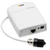
6 Hardware Overview 1 23 AXIS P12 Series Installation Guide 8 9 10 4 5 67 11 1 Power indicator LED 7 Main unit 2 Status indicator LED 8 Network connector see page 9 3 Network indicator LED 9 Control button 4 MicroSD card slot 10 Power connector see page 9 5 Camera connector, see page - Axis Communications P1214 | P12 Network Camera Series - Installation Guide - Page 7
P12 Series Installation Guide Page 7 AXIS P1204 sensor unit and included accessories AXIS P1214 sensor unit and included accessories AXIS P1214-E sensor unit and included accessories 16 18 17 17 12 13 14 15 19 ENGLISH 12 AXIS P1204 sensor unit 13 Cover 14 Straight mounting bracket - Axis Communications P1214 | P12 Network Camera Series - Installation Guide - Page 8
Page 8 AXIS P1224-E sensor unit and included accessories 20 17 AXIS P12 Series Installation Guide 17 Mounting bracket 20 AXIS P1224-E sensor unit - Axis Communications P1214 | P12 Network Camera Series - Installation Guide - Page 9
AXIS P12 Series Installation Guide Connectors Network - RJ45 Ethernet connector. Supports PoE (Power over Ethernet, class 2). Page 9 ENGLISH Due to local regulations or the environmental and electrical conditions in which the product is to be used, a shielded network W 12 Camera connector - - Axis Communications P1214 | P12 Network Camera Series - Installation Guide - Page 10
Page 10 Connection diagram 1 3.3 V max 50 mA 2 3 4 AXIS P12 Series Installation Guide SD card slot - A standard or high-capacity microSD card (not included) can be used for local recording with removable storage. Note: Before removal, the SD - Axis Communications P1214 | P12 Network Camera Series - Installation Guide - Page 11
AXIS P12 Series Installation Guide Page 11 Camera LED Indicators LED Color Indication Network Status Power Green Amber Unlit Green Amber Red Unlit Green Amber Steady for connection to a 100 MBit/s network. Flashes for network activity. Steady for connection to a 10 MBit/s network. Flashes - Axis Communications P1214 | P12 Network Camera Series - Installation Guide - Page 12
AXIS P12 Series Installation Guide Install the hardware ! IMPORTANT! - The casing of the main unit is not approved for outdoor use - the product may only be installed during installation. The main unit for the AXIS P1204/P1214/P1214-E/P1224-E can instructions for the appropriate camera model below. - Axis Communications P1214 | P12 Network Camera Series - Installation Guide - Page 13
P12 Series Installation Guide Page 13 AXIS P1204 Sensor Unit ! IMPORTANT! - The casing of the AXIS P1204 sensor unit is not approved for outdoor use - the product may only be installed in indoor environments. ENGLISH The AXIS P1204 can be mounted in three different ways: • flat on any surface - Axis Communications P1214 | P12 Network Camera Series - Installation Guide - Page 14
Page 14 AXIS P12 Series Installation Guide Angled Surface Installation 1. Fasten the angled mounting bracket to the wall or ceiling and align it so the arrows are vertical or horizontal. 3. Fasten the camera to the plate with the two screws. 4. Snap on the cover. 5. Proceed to Connect the cables, on - Axis Communications P1214 | P12 Network Camera Series - Installation Guide - Page 15
AXIS P12 Series Installation Guide Page 15 Covert Installation 1. Drill a hole with 3mm diameter in the straight mounting bracket to the wall. 3. Insert the camera into the bracket, and fasten with the stop screw. Ensure that the cone of the camera is flush with the wall. 4. Proceed to Connect - Axis Communications P1214 | P12 Network Camera Series - Installation Guide - Page 16
Page 16 AXIS P12 Series Installation Guide AXIS P1214/AXIS P1224-E Sensor Unit ! IMPORTANT! - The casing of the AXIS P1214 sensor unit is not approved for outdoor use - the product may only be installed in indoor environments. The AXIS P1214/AXIS P1224-E can be mounted behind any wall, with - Axis Communications P1214 | P12 Network Camera Series - Installation Guide - Page 17
P12 Series Installation Guide Page 17 AXIS P1214-E Sensor Unit The AXIS P1214-E can be mounted like the AXIS P1214/AXIS P1224-E, see instructions above. The AXIS P1214-E can also be mounted in the supplied outdoor housing. The cables can be routed through the wall directly into the housing, or - Axis Communications P1214 | P12 Network Camera Series - Installation Guide - Page 18
Page 18 AXIS P12 Series Installation Guide 3. Drill a hole through the wall or remove one of the punch-outs in the cover. 4. Fasten the plate to the wall using screws and plugs appropriate for the wall material. Ensure that the camera bracket is pointing towards the area to be monitored. If - Axis Communications P1214 | P12 Network Camera Series - Installation Guide - Page 19
AXIS P12 Series Installation Guide Page 19 Connect the cables 1. Optionally connect external input/output devices, e.g. alarm devices. See page 9 for information on the terminal connector pins. 2. Connect the main unit to the network using a shielded network cable. 3. Connect the sensor unit to - Axis Communications P1214 | P12 Network Camera Series - Installation Guide - Page 20
Page 20 AXIS P12 Series Installation Guide Access the Axis Product Use the software provided on the Installation and Management Software CD to assign an IP address, set the password and access the video stream. The Live View Page The product's Live View page appears in your browser. Click Setup to - Axis Communications P1214 | P12 Network Camera Series - Installation Guide - Page 21
has been reset to the factory default settings. Further Information The User Manual is available from the Axis Web site at www.axis.com Tip! Visit www.axis.com/techsup to check if there is updated firmware available for your network camera. To see the currently installed firmware version, see - Axis Communications P1214 | P12 Network Camera Series - Installation Guide - Page 22
- Axis Communications P1214 | P12 Network Camera Series - Installation Guide - Page 23
d'installer le produit Axis. Conservez le Guide d'installation pour une utilisation ultérieure. • Conservez le produit Axis dans un environnement sec et aéré. • Évitez d'exposer le produit Axis aux vibrations, aux chocs ou à une forte pression. N'installez pas le produit sur un support instable - Axis Communications P1214 | P12 Network Camera Series - Installation Guide - Page 24
ît lorsque la pile doit être remplacée. Ne remplacez la pile qu'en cas de nécessité ! Si la pile doit être remplacée, veuillez contacter www.axis.com/techsup pour obtenir de l'aide. • Jetez les piles usagées conformément aux consignes du fabricant. • Le remplacement incorrect de la pile peut entra - Axis Communications P1214 | P12 Network Camera Series - Installation Guide - Page 25
fixation oblique, couvercle AXIS P1214/AXIS P1224-E: Support de fixation AXIS P1214-E: Support de fixation, boîtier externe Le CD d'installation et de gestion du logiciel, y compris les outils d'installation et au autre logiciel Documentation imprimée Guide d'installation de la série AXIS P12 (le - Axis Communications P1214 | P12 Network Camera Series - Installation Guide - Page 26
Page 26 Vue d'ensemble du matériel 1 23 Séríe AXIS P12 Guide d'installation 8 9 10 4 5 67 11 1 Voyant DEL d'alimentation 7 Unité principale 2 Voyant DEL d'état 8 Connecteur réseau, voir page 29 3 Voyant DEL réseau 9 Bouton de commande 4 Emplacement carte SD ( - Axis Communications P1214 | P12 Network Camera Series - Installation Guide - Page 27
Séríe AXIS P12 Guide d'installation Page 27 Unité optique AXIS P1204 et accessoires inclus Unité optique AXIS P1214 et accessoires inclus Unité optique AXIS P1214-E et accessoires inclus 16 18 17 17 12 13 14 15 19 FRANÇAIS 12 Unité optique AXIS P1204 13 Cache de protection 14 Support - Axis Communications P1214 | P12 Network Camera Series - Installation Guide - Page 28
Page 28 Unité optique AXIS P1224-E et accessoires inclus 20 17 Séríe AXIS P12 Guide d'installation 17 Support de fixation 20 Unité optique AXIS P1224-E - Axis Communications P1214 | P12 Network Camera Series - Installation Guide - Page 29
Séríe AXIS P12 Guide d'installation Page 29 Connecteurs Réseau - Connecteur Ethernet RJ45. Prend en charge PoE (alimentation par Ethernet, classe 2). Conformément à la règlementation locale et étant donné les conditions é - Axis Communications P1214 | P12 Network Camera Series - Installation Guide - Page 30
Page 30 Séríe AXIS P12 Guide d'installation Connecteur pour terminaux d'E/S - À utiliser dans les applications pour, par exemple, la détection de mouvement, le déclenchement d'évènement, l'enregistrement image par image et les notifications d'alarmes. - Axis Communications P1214 | P12 Network Camera Series - Installation Guide - Page 31
Séríe AXIS P12 Guide d'installation Schéma de connexion 1 3.3 V max 50 mA 2 3 4 Page 31 FRANÇAIS Logement de la carte SD - Une carte SD standard ou de grande capacité (pas - Axis Communications P1214 | P12 Network Camera Series - Installation Guide - Page 32
Page 32 Séríe AXIS P12 Guide d'installation Voyant DEL de caméra DEL Couleur Indication Réseau Vert Orange État Alimentation Éteint Vert Orange Rouge Éteint Vert Orange Continu en cas de connexion à - Axis Communications P1214 | P12 Network Camera Series - Installation Guide - Page 33
AXIS P12 Guide d'installation Page 33 Installation du matériel ! IMPORTANT ! - Le boîtier de votre unité principale n'est pas approuvé pour une utilisation extérieure. Le produit doit être uniquement install 3. Continuez avec les instructions ci-après pour le modèle de caméra approprié. FRANÇAIS - Axis Communications P1214 | P12 Network Camera Series - Installation Guide - Page 34
pas approuvé pour une utilisation extérieure. Le produit doit être uniquement installé en intérieur. L'AXIS P1204 peut être installée de trois manières différentes : • à plat sur toute surface • en oblique sur toute surface, à l'aide du support de fixation oblique • caché derrière un matériau mince - Axis Communications P1214 | P12 Network Camera Series - Installation Guide - Page 35
Séríe AXIS P12 Guide d'installation Page 35 Installation sur surface oblique 1. Fixez le support de montage au mur ou au plafond à l'aide de vis ou de prises appropriées pour le mur ou le plafond. Assurez-vous que le support est orienté vers la zone à surveiller. 2. Assemblez la plaque et la vis - Axis Communications P1214 | P12 Network Camera Series - Installation Guide - Page 36
Séríe AXIS P12 Guide d'installation Installation cachée 1. Percez un trou de 3 mm de diamètre dans le mur ou le plafond Si la largeur du matériel est supérieure à 1 mm, il pourrait être nécessaire d'élargir le trou à l'aide d'une fraise. 2. Enlevez la protection de l'adhésif et fixez le support de - Axis Communications P1214 | P12 Network Camera Series - Installation Guide - Page 37
Séríe AXIS P12 Guide d'installation Page 37 Unité optique AXIS P1214/AXIS P1224-E ! IMPORTANT ! - Le boîtier de l'unité optique de l'AXIS P1214 n'est pas approuvé pour une utilisation extérieure. Le produit doit être uniquement installé en intérieur. L'AXIS P1214 peut être montée derrière tout - Axis Communications P1214 | P12 Network Camera Series - Installation Guide - Page 38
Page 38 Séríe AXIS P12 Guide d'installation Unité optique AXIS P1214-E L'AXIS P1214-E peut être installée de la même manière que l'AXIS P1214/AXIS P1224-E, voir les instructions mentionnées plus haut. L'AXIS P1214-E peut également être installé dans le boîtier d'installation en extérieur fourni. - Axis Communications P1214 | P12 Network Camera Series - Installation Guide - Page 39
Séríe AXIS P12 Guide d'installation Page 39 3. Percez un trou dans le mur ou enlevez une des ouvertures sur le couvercle. 4. Fixez la plaque au mur à l'aide de vis ou de prises appropriées pour le mur. Assurez-vous que le support de la caméra est orienté vers la zone à surveiller. Si le câble est - Axis Communications P1214 | P12 Network Camera Series - Installation Guide - Page 40
Page 40 Séríe AXIS P12 Guide d'installation Branchement des câbles 1. Si vous le souhaitez, connectez des dispositifs d'entrée/sortie externes, par exemple des systèmes d'alarme. Reportez-vous à la page 29 pour - Axis Communications P1214 | P12 Network Camera Series - Installation Guide - Page 41
Séríe AXIS P12 Guide d'installation Page 41 Accès au produit Axis Utilisez le logiciel fourni sur le CD d'installation et de gestion du logiciel pour attribuer une adresse IP, configurez le mot de passe et accédez au flux vidéo. La page Live View (Vidéo en direct) La page de vidéo en direct s' - Axis Communications P1214 | P12 Network Camera Series - Installation Guide - Page 42
Page 42 Séríe AXIS P12 Guide d'installation Rétablissement des paramètres d'usine par défaut Si vous devez rétablir le produit aux paramètres d'usine par défaut, procédez comme suit : 1. Débranchez l'alimentation 2. - Axis Communications P1214 | P12 Network Camera Series - Installation Guide - Page 43
instabilen oder vibrierenden Oberflächen oder Mauern, da dadurch das Produkt beschädigt werden könnte. • Verwenden Sie bei der Installation des Axis Produkts nur geeignetes Werkzeug; zu hoher Kraftaufwand kann das Produkt beschädigen. • Verwenden Sie keine chemischen, ätzenden oder aerosolhaltigen - Axis Communications P1214 | P12 Network Camera Series - Installation Guide - Page 44
Batteriewechsel Dieses Axis-Produkt ist mit einer 3,0 V BR2032 oder CR2032 Lithium-Batterie als Stromversorgung für Batteriewechsel erforderlich ist. Die Batterie sollte erst bei Bedarf gewechselt werden. Unter www.axis.com/techsup finden Sie Informationen darüber, was Sie beim Austausch der Batterie - Axis Communications P1214 | P12 Network Camera Series - Installation Guide - Page 45
P1214/AXIS P1214-E/AXIS P1224-E 2-polige Netzklemmleiste 4-polige E/A Anschlussklemmleiste Alle Varianten: Montageschiene AXIS P1204: Gerade Montagekonsole, Winkelkonsole, Abdeckung AXIS P1214/AXIS P1224-E: Montagekonsole AXIS P1214-E: Montagekonsole, Gehäuse für Montage im Freien CD Installations - Axis Communications P1214 | P12 Network Camera Series - Installation Guide - Page 46
Seite 46 Die Serie AXIS P12 Installationsanleitung Übersicht über die Hardware 1 23 8 9 10 4 5 67 11 1 Betriebsanzeige LED 7 Hauptgerät 2 Statusanzeige LED 8 Für den Netzwerkanschluss siehe Seite 49 3 Netzwerkanzeige LED 9 Steuertaste 4 Einschub für SD - Axis Communications P1214 | P12 Network Camera Series - Installation Guide - Page 47
Einheit und beigefügtes Zubehör beigefügtes Zubehör 16 18 17 17 12 13 14 15 19 DEUTSCH 12 AXIS P1204 Optische Einheit 13 Abdeckung 14 Gerade Montagekonsole 15 Winkelkonsole 16 AXIS P1214 Optische Einheit 17 Montagekonsole 18 AXIS P1214-E Optische Einheit 19 Gehäuse für Montage im Freien - Axis Communications P1214 | P12 Network Camera Series - Installation Guide - Page 48
Seite 48 AXIS P1224-E Optische Einheit und beigefügtes Zubehör 20 17 Die Serie AXIS P12 Installationsanleitung 17 Montagekonsole 20 AXIS P1224-E Optische Einheit - Axis Communications P1214 | P12 Network Camera Series - Installation Guide - Page 49
Die Serie AXIS P12 Installationsanleitung Seite 49 Anschlüsse Netzwerk - RJ45-Ethernetanschluss. Unterstützt PoE (Power over Ethernet, Klasse 2). DEUTSCH Aufgrund der örtlichen Bestimmungen oder der Umgebungs- oder - Axis Communications P1214 | P12 Network Camera Series - Installation Guide - Page 50
Seite 50 Die Serie AXIS P12 Installationsanleitung Funktion Eingang Anschlussnummer 3 Ausgang 4 Anschlussplan Hinweise Digitaleingang - Zum Aktivieren mit dem Massekontakt verbinden; zum Deaktivieren schweben lassen (oder nicht anschließen). Digitalausgang - Interne - Axis Communications P1214 | P12 Network Camera Series - Installation Guide - Page 51
Die Serie AXIS P12 Installationsanleitung Seite 51 Kamera LED Anzeigen LED Farbe Anzeige Netzwerk Status Keine Verbindung zwischen Optische Einheit und Hauptgerät. Normaler Betrieb. Blinkt während der Firmware-Aktualisierung grün/gelb. Hinweis: Die Status- und Netzwerk-LEDs können so - Axis Communications P1214 | P12 Network Camera Series - Installation Guide - Page 52
nur im geschlossenen Raum installiert werden. Notieren Sie die Seriennummer (S/N) auf dem Typenschild. Diese kann für die Installation notwendig sein. Das Hauptgerät für die AXIS P1204/P1214/P1214-E kann auf eine DIN Schiene montiert werden oder es wird die mitgelieferte Montageschiene verwendet - Axis Communications P1214 | P12 Network Camera Series - Installation Guide - Page 53
das Produkt darf nur im geschlossenen Raum installiert werden. Das Gerät AXIS P1204 kann auf drei verschiedene Arten montiert werden: • flach auf einer hinter einem Metallblech im Türpfosten oder der Front eines Geldautomaten. Installation auf ebener Oberfläche 1 Befestigen Sie die Kamera an der - Axis Communications P1214 | P12 Network Camera Series - Installation Guide - Page 54
Seite 54 Die Serie AXIS P12 Installationsanleitung Installation auf Oberfläche im Winkel 1 Befestigen Sie die Winkelkonsole an der Wand oder Decke mittels Schrauben und Verschlüssen, die für das Wand-/Deckenmaterial geeignet sind. - Axis Communications P1214 | P12 Network Camera Series - Installation Guide - Page 55
Die Serie AXIS P12 Installationsanleitung Seite 55 Verdeckte Installation 1 Bohren Sie ein Loch von 3 mm in Wand oder Decke. Ist das Material stärker als 1 mm, dann muss das Loch eventuell mit einem Halssenker - Axis Communications P1214 | P12 Network Camera Series - Installation Guide - Page 56
Seite 56 Die Serie AXIS P12 Installationsanleitung AXIS P1214/AXIS P1224-E Optische Einheit ! WICHTIG! - Das Gehäuse der optischen Einheit der AXIS P1214 ist nicht für den Einsatz im Freien zugelassen - das Produkt darf nur im geschlossenen Raum installiert werden. Die AXIS P1214 kann hinter - Axis Communications P1214 | P12 Network Camera Series - Installation Guide - Page 57
Die Serie AXIS P12 Installationsanleitung Seite 57 AXIS P1214-E Optische Einheit Die AXIS P1214-E kann ebenso montiert werden wie die AXIS P1214/AXIS P1224-E, siehe Anweisungen oben. Die AXIS P1214-E kann auch im mitgelieferten Gehäuse für Einsätze im Freien montiert werden. Die Kabel können durch - Axis Communications P1214 | P12 Network Camera Series - Installation Guide - Page 58
Seite 58 Die Serie AXIS P12 Installationsanleitung 3. Bohren Sie ein Loch durch die Wand oder entfernen Sie eine der Ausstanzungen in der Abdeckung. 4. Befestigen Sie die Platte an der Wand - Axis Communications P1214 | P12 Network Camera Series - Installation Guide - Page 59
Die Serie AXIS P12 Installationsanleitung Seite 59 Schließen Sie die Kabel an 1 Sie können zusätzlich externe E/A-Geräte, wie z. B. Alarmanlagen, anschließen. Siehe Seite 49 bezü - Axis Communications P1214 | P12 Network Camera Series - Installation Guide - Page 60
Seite 60 Die Serie AXIS P12 Installationsanleitung Ihr Axis Produkt Verwenden Sie die Software von der Installations- und Verwaltungs-Software CD, zum Einrichten des Produkts zu öffnen. Nun können Sie Ihr Axis Produkt entsprechend einstellen. Einrichten - Bietet alle Tools für die Konfiguration - Axis Communications P1214 | P12 Network Camera Series - Installation Guide - Page 61
. Weitere Informationen Das Benutzerhandbuch kann auf der Axis Website unter www.axis.com abgerufen werden. Tipp! Unter „www.axis.com/techsup" finden Sie Firmware-Aktualisierungen für Ihre NetzwerkKamera. Für die aktuell installierte Firmware-Version siehe Einrichten > Über . Erfahren Sie mehr - Axis Communications P1214 | P12 Network Camera Series - Installation Guide - Page 62
- Axis Communications P1214 | P12 Network Camera Series - Installation Guide - Page 63
o pareti instabili o vibranti, poiché ciò potrebbe danneggiare il prodotto. • Utilizzare solo strumenti idonei quando si installa il prodotto Axis. Una forza eccessiva potrebbe danneggiare il prodotto. • Non utilizzare sostanze chimiche, agenti caustici o detergenti spray. Utilizzare un panno umido - Axis Communications P1214 | P12 Network Camera Series - Installation Guide - Page 64
à essere sostituita. La batteria non deve essere sostituita a meno che non sia necessario. Se la batteria non deve essere sostituita, contattare www.axis.com/techsup per assistenza. • Smaltire le batterie usate secondo le istruzioni del produttore. • Rischio di esplosione se la batteria non viene - Axis Communications P1214 | P12 Network Camera Series - Installation Guide - Page 65
Telecamera di rete Connettori Accessori di montaggio CD Materiali stampati Modelli/varianti/note Unità principale Unità Sensore AXIS P1204/AXIS P1214/AXIS P1214-E/AXIS P1224-E Morsettiera per l'alimentazione a 2 pin Morsettiera connettore I/O a 4 pin Tutte le varianti: Barra per il montaggio - Axis Communications P1214 | P12 Network Camera Series - Installation Guide - Page 66
Pagina 66 Panoramica dell'hardware 1 23 Serie AXIS P12 Guida all'installazione 8 9 10 4 5 67 11 1 Indicatore di alimentazione (LED) 2 LED di stato 3 Indicatore di rete (LED) 4 Slot per scheda SD (scheda microSD) 5 Connettore - Axis Communications P1214 | P12 Network Camera Series - Installation Guide - Page 67
e accessori inclusi inclusi 16 18 17 17 12 13 14 15 19 ITALIANO 12 AXIS P1204 Unità Sensore 16 AXIS P1214 Unità Sensore 13 Copertura 17 Staffa di montaggio 14 Staffa di montaggio dritta 18 AXIS P1214-E Unità Sensore 15 Staffa di montaggio ad angolo 19 Alloggiamento per esterni - Axis Communications P1214 | P12 Network Camera Series - Installation Guide - Page 68
Pagina 68 AXIS P1224-E Unità Sensore e accessori inclusi 20 17 Serie AXIS P12 Guida all'installazione 17 Staffa di montaggio 20 AXIS P1224-E Unità Sensore - Axis Communications P1214 | P12 Network Camera Series - Installation Guide - Page 69
Guida all'installazione della videocamera Serie AXIS P12 Pagina 69 Connettori Rete - Connettore Ethernet RJ45. Supporto per PoE (Power over Ethernet, classe 2). A causa delle disposizioni locali e delle condizioni ambientali ed elettriche in - Axis Communications P1214 | P12 Network Camera Series - Installation Guide - Page 70
Pagina 70 Serie AXIS P12 Guida all'installazione Funzione Ingresso Uscita Numero pin 3 4 Note Ingresso digitale - connettere a GND per l'attivazione o lasciarlo isolato (o scollegato) per disattivarlo. Uscita digitale - connessione interna - Axis Communications P1214 | P12 Network Camera Series - Installation Guide - Page 71
Guida all'installazione della videocamera Serie AXIS P12 Pagina 71 Indicatori LED della telecamera LED Colore à Sensore e l'unità principale. Normale utilizzo. Luce lampeggiante verde/gialla: aggiornamento firmware. Nota: I LED di stato e della rete possono essere configurati per rimanere - Axis Communications P1214 | P12 Network Camera Series - Installation Guide - Page 72
interni. Prendere nota del numero seriale (S/N) situato sull'etichetta del prodotto. Il numero è talvolta richiesto durante l'installazione. L'unità principale per la AXIS P1204/P1214/P1214-E può essere montata su una barra DIN o utilizzando la barra di montaggio fornita. 1. Se si utilizza la barra - Axis Communications P1214 | P12 Network Camera Series - Installation Guide - Page 73
non è approvato per l'utilizzo in ambienti esterni. Il prodotto può essere installato soltanto in ambienti interni. La AXIS P1204 può essere montata in tre modi differenti: • piatta su qualsiasi superficie • ad angolo su qualsiasi superficie, utilizzando la staffa di fissaggio ad angolo • nascosta - Axis Communications P1214 | P12 Network Camera Series - Installation Guide - Page 74
Pagina 74 Serie AXIS P12 Guida all'installazione Installazione su superficie ad angolo 1. Assicurare la staffa di montaggio ad angolo a muro o al soffitto, utilizzando viti e tasselli appropriati per il - Axis Communications P1214 | P12 Network Camera Series - Installation Guide - Page 75
Guida all'installazione della videocamera Serie AXIS P12 Pagina 75 Installazione nascosta 1. Fare un foro di 3 mm di diametro nel muro o nel soffitto. Se il materiale è più spesso di 1 mm, potrebbe essere - Axis Communications P1214 | P12 Network Camera Series - Installation Guide - Page 76
Unità sensore della telecamera AXIS P1214/AXIS P1224-E ! IMPORTANTE! - L'alloggiamento dell'unità sensore della telecamera AXIS P1214 non è approvato per l'utilizzo in ambienti esterni. Il prodotto può essere installato soltanto in ambienti interni. La AXIS P1214 può essere montata - Axis Communications P1214 | P12 Network Camera Series - Installation Guide - Page 77
Guida all'installazione della videocamera Serie AXIS P12 Pagina 77 Unità sensore della telecamera AXIS P1214-E La AXIS P1214-E può essere montata come la AXIS P1214/AXIS P1224-E, vedere le istruzione precedenti. La AXIS P1214-E può essere montata anche nell'alloggiamento per esterni fornito. I - Axis Communications P1214 | P12 Network Camera Series - Installation Guide - Page 78
Pagina 78 Serie AXIS P12 Guida all'installazione 3. Effettuare un foro nel muro o rimuovere una delle forature nella copertura. 4. Fissare la piastra al muro utilizzando viti e tasselli appropriati per - Axis Communications P1214 | P12 Network Camera Series - Installation Guide - Page 79
Guida all'installazione della videocamera Serie AXIS P12 Pagina 79 Collegamento dei cavi 1. Opzionalmente, è . Se necessario, è possibile accorciare il cavo. Per ulteriori informazioni, vedere il Manuale per l'utente. 4. Collegare l'alimentazione mediante uno dei metodi elencati di seguito: - Axis Communications P1214 | P12 Network Camera Series - Installation Guide - Page 80
P12 Guida all'installazione Accesso al prodotto Axis Utilizzare il software fornito nel CD di installazione e gestione per assegnare un indirizzo IP, impostare la password e accedere al flusso video. La pagina Live View La pagina Live View del prodotto viene visualizzata nel browser. Fare clic su - Axis Communications P1214 | P12 Network Camera Series - Installation Guide - Page 81
Per conoscere la versione installata del firmware, vedere Setup > About (Impostazioni > informazioni). Ulteriori informazioni Per utili corsi di formazione, webinar, tutorial e guide, visitare il centro di apprendimento di Axis all'indirizzo www.axis.com/academy. ITALIANO Garanzia Per informazioni - Axis Communications P1214 | P12 Network Camera Series - Installation Guide - Page 82
- Axis Communications P1214 | P12 Network Camera Series - Installation Guide - Page 83
la Guía deinstalación para poder consultarla en el futuro. • Guarde el producto Axis en un entorno seco y ventilado. • Evite exponer el producto Axis a vibraciones, golpes o presiones excesivas. No instale el producto en soportes inestables ni en superficies o paredes inestables o con vibraciones - Axis Communications P1214 | P12 Network Camera Series - Installation Guide - Page 84
necesario sustituir la batería. No se debe sustituir la batería a menos que sea necesario. Si necesita sustituir la batería, visite la página www.axis.com/techsup para recibir asistencia. • Deseche las baterías usadas según las instrucciones del fabricante. • Existe peligro de explosión si la bater - Axis Communications P1214 | P12 Network Camera Series - Installation Guide - Page 85
otra cuestión relativa al uso del producto, consulte el Manual del usuario, disponible en www.axis.com. Pasos para la instalación 1. Comprobación del CD Modelos/variantes/notas Unidad principal Unidad óptica AXIS P1204/AXIS P1214/AXIS P1214-E/AXIS P1224-E Bloque de terminales de alimentación de 2 - Axis Communications P1214 | P12 Network Camera Series - Installation Guide - Page 86
Página 86 Presentación del hardware 1 23 Serie AXIS P12 Guía de instalación 8 9 10 4 5 67 11 1 LED indicador de alimentación 7 Unidad principal 2 LED indicador de estado 8 Conector de red; consulte la página 89 3 LED - Axis Communications P1214 | P12 Network Camera Series - Installation Guide - Page 87
incluidos accesorios incluidos 16 18 17 17 12 13 14 15 19 ESPAÑOL 12 Unidad óptica AXIS P1204 16 Unidad óptica AXIS P1214 13 Cubierta 17 Escuadra de montaje 14 Escuadra de montaje recto 18 Unidad óptica AXIS P1214-E 15 Escuadra de montaje inclinado 19 Carcasa para exteriores - Axis Communications P1214 | P12 Network Camera Series - Installation Guide - Page 88
Página 88 Unidad óptica AXIS P1214-E y accesorios incluidos 20 17 Serie AXIS P12 Guía de instalación 17 Escuadra de montaje 20 Unidad óptica AXIS P1224-E - Axis Communications P1214 | P12 Network Camera Series - Installation Guide - Page 89
Serie AXIS P12 Guía de instalación Página 89 Conectores Red - Conector Ethernet RJ45. Admite PoE (alimentación a través de Ethernet, clase 2). Debido a la normativa local o a las condiciones ambientales y - Axis Communications P1214 | P12 Network Camera Series - Installation Guide - Page 90
Página 90 Serie AXIS P12 Guía de instalación Función Entrada Salida Número de pines 3 4 Notas Entrada digital: conéctela a TIERRA para activarla o déjela suelta (o desconectada) para desactivarla. Salida digital: - Axis Communications P1214 | P12 Network Camera Series - Installation Guide - Page 91
Serie AXIS P12 Guía de instalación Página 91 Indicadores LED de cámara LED Color Indicación óptica y la unidad principal. Funcionamiento normal. Parpadea en verde/ámbar durante la actualización del firmware. Nota: Los LED de estado y red se pueden configurar para que se queden apagados durante - Axis Communications P1214 | P12 Network Camera Series - Installation Guide - Page 92
. Anote el número de serie (S/N) que aparece en la etiqueta del producto. Es posible que lo necesite durante la instalación. La unidad principal de la AXIS P1204/P1214/P1214-E se puede montar en un carril DIN o mediante el carril de montaje proporcionado. 1. Si usa el carril de montaje, fíjelo a la - Axis Communications P1214 | P12 Network Camera Series - Installation Guide - Page 93
P1204 no está aprobada para su uso en exteriores; el producto solo se puede instalar en interiores. La AXIS P1204 se puede montar de tres formas distintas: • plana sobre cualquier superficie • inclinada sobre cualquier superficie mediante la escuadra de montaje inclinado • de forma encubierta - Axis Communications P1214 | P12 Network Camera Series - Installation Guide - Page 94
Página 94 Serie AXIS P12 Guía de instalación Instalación en una superficie inclinada 1. Fije la escuadra de montaje inclinado a la pared o al techo con los tornillos y tacos adecuados para - Axis Communications P1214 | P12 Network Camera Series - Installation Guide - Page 95
Serie AXIS P12 Guía de instalación Página 95 Instalación encubierta 1. Perfore un orificio de 3 mm de diámetro en la pared o el techo. Si el material tiene - Axis Communications P1214 | P12 Network Camera Series - Installation Guide - Page 96
P12 Guía de instalación Unidad óptica AXIS P1214/AXIS P1224-E ! IMPORTANTE: la carcasa de la unidad óptica AXIS P1214 no está aprobada para su uso en exteriores; el producto solo se puede instalar en interiores. La AXIS P1214 puede montarse tras cualquier pared con solo una pequeña apertura para - Axis Communications P1214 | P12 Network Camera Series - Installation Guide - Page 97
P12 Guía de instalación Página 97 Unidad óptica AXIS P1214-E La AXIS P1214-E puede montarse igual que la AXIS P1214/AXIS P1224-E; consulte las instrucciones proporcionadas previamente. La AXIS P1214-E también puede montarse en la carcasa para exteriores proporcionada. Los cables se pueden pasar - Axis Communications P1214 | P12 Network Camera Series - Installation Guide - Page 98
Página 98 Serie AXIS P12 Guía de instalación 3. Perfore un orificio a través de la pared o extraiga el material de uno de los orificios troquelados de la cubierta. 4. Fije la - Axis Communications P1214 | P12 Network Camera Series - Installation Guide - Page 99
Serie AXIS P12 Guía de instalación Página 99 Conexión de los cables 1. También unidad principal. Si fuese necesario, el cable se puede acortar. Para obtener más información, consulte el Manual del usuario. 4. Conecte la alimentación mediante uno de los métodos especificados a continuación: • PoE - Axis Communications P1214 | P12 Network Camera Series - Installation Guide - Page 100
Guía de instalación Acceso al producto Axis Utilice el software suministrado en el CD del software de instalación y gestión para asignar una dirección IP, establecer la contraseña y acceder a la transmisión de vídeo. La página Visualización en directo La página Visualización en directo del producto - Axis Communications P1214 | P12 Network Camera Series - Installation Guide - Page 101
ha restablecido la configuración predeterminada de fábrica del producto. Más información El Manual del usuario está disponible en el sitio web de Axis en www.axis.com. Consejo: Visite www.axis.com/techsup para comprobar si hay disponible firmware actualizado para su cámara de red. Para ver la versi - Axis Communications P1214 | P12 Network Camera Series - Installation Guide - Page 102
- Axis Communications P1214 | P12 Network Camera Series - Installation Guide - Page 103
- Axis Communications P1214 | P12 Network Camera Series - Installation Guide - Page 104
Installation Guide AXIS P12 Network Camera Series © Axis Communications AB, 2010-2014 Ver.2.1 Printed: May 2014 Part No. 57678
-
 1
1 -
 2
2 -
 3
3 -
 4
4 -
 5
5 -
 6
6 -
 7
7 -
8
-
9
-
10
-
11
-
12
-
13
-
14
-
15
-
16
-
17
-
18
-
19
-
20
-
21
-
22
-
23
-
24
-
25
-
26
-
27
-
28
-
29
-
30
-
31
-
32
-
33
-
34
-
35
-
36
-
37
-
38
-
39
-
40
-
41
-
42
-
43
-
44
-
45
-
46
-
47
-
48
-
49
-
50
-
51
-
52
-
53
-
54
-
55
-
56
-
57
-
58
-
59
-
60
-
61
-
62
-
63
-
64
-
65
-
66
-
67
-
68
-
69
-
70
-
71
-
72
-
73
-
74
-
75
-
76
-
77
-
78
-
79
-
80
-
81
-
82
-
83
-
84
-
85
-
86
-
87
-
88
-
89
-
90
-
91
-
92
-
93
-
94
-
95
-
96
-
97
-
98
-
99
-
100
-
101
-
102
-
103
-
104
 |
 |

ENGLISH
DEUTSCH
ITALIANO
ESPAÑOL
INSTALLATION GUIDE
FRAN
Ç
AIS
AXIS P12 Network Camera Series
AXIS P1204 Network Camera
AXIS P1214 Network Camera
AXIS P1214-E Network Camera
AXIS P1224-E Network Camera