Behringer 110 VCO/VCF/VCA Quick Start Guide
Behringer 110 VCO/VCF/VCA Manual
 |
View all Behringer 110 VCO/VCF/VCA manuals
Add to My Manuals
Save this manual to your list of manuals |
Behringer 110 VCO/VCF/VCA manual content summary:
- Behringer 110 VCO/VCF/VCA | Quick Start Guide - Page 1
Guide 110 VCO/VCF/VCA Legendary Analog VCO/VCF/VCA Module for Eurorack Controls (1) (2) (9) (3) (4) (5) (6) (7) (9) VCF/VCA SIG IN - Connect incoming signals via 3.5 mm TS cables. (10) SIG LEVEL - Adjust the level of the signals connected to the inputs. (11) VCA OUT - Sends the VCA MANUAL - Behringer 110 VCO/VCF/VCA | Quick Start Guide - Page 2
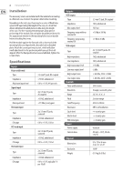
2 110 VCO/VCF/VCA Installation The necessary screws are included with the module for mounting High output noise Low output noise Controls Pulse width manual Waveform Range Pitch Cutoff frequency Resonance Sig in level Mod in level VCA initial gain Power Power supply Current draw Physical Dimensions - Behringer 110 VCO/VCF/VCA | Quick Start Guide - Page 3
Quick Start Guide 3 LEGAL DISCLAIMER Music Tribe accepts no liability for any loss which may be suffered by any person who relies either wholly or in part upon
-
 1
1 -
 2
2 -
 3
3
 |
 |
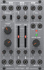
Quick Start Guide
110 VCO/VCF/VCA
Legendary Analog VCO/VCF/VCA
Module for Eurorack
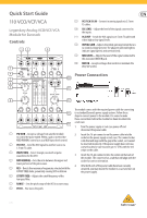
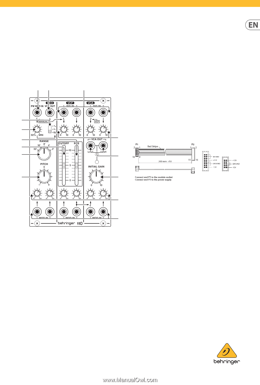
Controls
(1)
PW MOD
– Accepts a voltage from another module
to control the pulse width. When a jack is inserted the
MOD MANUAL control acts as a MOD input level control.
(2)
VCO OUT
– Send the VCO signal to another source via
3.5 mm TS cable.
(3)
WAVEFORM
– Select triangle, sawtooth or pulse
waveforms for the VCO.
(4)
MOD MANUAL
– Sets the ratio between the upper and
lower portions of the pulse wave.
(5)
RES
– Boosts the resonance frequencies selected with the
CUTOFF FREQ slider, potentially causing VCF oscillation.
(6)
CUTOFF FREQ
– Adjusts the cutoff frequency of the
low-pass filter.
(7)
RANGE
– Sets the pitch range of the VCO in octave steps.
(8)
PITCH
– Fine tunes the pitch.
(9)
VCF/VCA SIG IN
– Connect incoming signals via 3.5 mm
TS cables.
(10)
SIG LEVEL
– Adjust the level of the signals connected to
the inputs.
(11)
VCA OUT
– Sends the VCA signal via 3.5 mm TS cable with
either high or low signal levels.
(12)
INITIAL GAIN
– Adjusts the initial gain level when there is
no control voltage present. The adjacent LEDs will light to
indicate signal (green) and overload (red).
(13)
MOD LEVEL
– Adjusts the level of the signal connected to
the associated MOD IN jack.
(14)
MOD IN
– Accepts voltages that control or modulate the
VCO, VCF or VCA.
Power Connection
The module comes with the required power cable for connecting
to a standard Eurorack power supply system. Follow these
steps to connect power to the module. It is easier to make
these connections before the module has been mounted into
a rack case.
1.
Turn the power supply or rack case power off and
disconnect the power cable.
2.
Insert the 16-pin connector on the power cable into the
socket on the power supply or rack case. The connector has
a tab that will align with the gap in the socket, so it cannot
be inserted incorrectly. If the power supply does not have
a keyed socket, be sure to orient pin 1 (-12 V) with the red
stripe on the cable.
3.
Insert the 10-pin connector into the socket on the back of
the module. The connector has a tab that will align with the
socket for correct orientation.
4.
After both ends of the power cable have been securely
attached, you may mount the module in a case and turn on
the power supply.
(2)
(9)
(1)
(3)
(4)
(5)
(6)
(7)
(8)
(10)
(11)
(12)
(13)
(14)
V 1.0