Behringer 140 DUAL ENVELOPE/LFO Quick Start Guide
Behringer 140 DUAL ENVELOPE/LFO Manual
 |
View all Behringer 140 DUAL ENVELOPE/LFO manuals
Add to My Manuals
Save this manual to your list of manuals |
Behringer 140 DUAL ENVELOPE/LFO manual content summary:
- Behringer 140 DUAL ENVELOPE/LFO | Quick Start Guide - Page 1
Start Guide 140 DUAL ENVELOPE/ LFO Legendary Analog Dual Envelope/LFO Module for Eurorack Controls (3) (4) (5) (6) (1) (7) (2) (11) (14) (12) (15) (8) (8) FREQ RANGE - Sets the oscillating frequency range of the LFO in 3 steps. (9) FREQ - Manually sets the oscillating frequency of the LFO. (10 - Behringer 140 DUAL ENVELOPE/LFO | Quick Start Guide - Page 2
Max input level Outputs Envelope 1/2 out Impedance Max output level LFO output Impedance Max output level Controls Attack Decay Sustain Release Manual gate switch Frequency range switch 3.5 mm jack, DC coupled 50 kΩ +3 V +10 V 3.5 mm jack, DC coupled 100 kΩ +/-10 V 1 V / octave 3.5 mm jack
-
 1
1 -
 2
2
 |
 |

Quick Start Guide
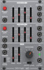
140 DUAL ENVELOPE/ LFO
Legendary Analog Dual Envelope/LFO
Module for Eurorack
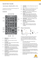
Controls
(1)
MANUAL GATE
– Press and hold to start the
envelope cycle.
(2)
EXT GATE
– Connect a gate signal to control the
envelope cycle.
(3)
ATTACK TIME
– Adjusts the rate at which the envelope
reaches its peak voltage.
(4)
DECAY TIME
– Adjusts the rate at which the envelope
decays from its peak level to its designated sustain level.
(5)
SUSTAIN LEVEL
– Controls the level at which the
envelope remains after its peak but before release,
sustaining as long as the input signal is present or the
manual gate switch is held down.
(6)
RELEASE TIME
– Controls how quickly the envelope
falls after the input signal stops or the manual gate
switch is released.
(7)
ENV OUTPUTS
– Send up to 2 positive waveforms
and a negative waveform to other modules via these
output connectors.
(8)
FREQ RANGE
– Sets the oscillating frequency range of the
LFO in 3 steps.
(9)
FREQ
– Manually sets the oscillating frequency of the LFO.
(10)
DELAY
– Sets the time from when a trigger signal is
received until the LFO begins operating again.
(11)
FREQ CV IN
– Accepts voltage for controlling the LFO
frequency with an external source.
(12)
TRIGGER
- Connect a trigger signal to turn the LFO
off
until the end of the trigger cycle. This works along
with the Delay slider, and the LFO recovery takes about
20 seconds. The rear panel features a jumper that can be
removed if you don’t want the LFO to be re-triggered.
(13)
OUTPUT LEVEL
– Selects between standard or 1/10th
output level for the LFO OUT jacks.
(14)
WAVEFORM
– Select between sine, triangle,
pulse, sawtooth or reverse sawtooth for the LFO
waveform output.
(15)
LFO OUT
– Sends the LFO output to other modules.
The upper jack is non-inverting and the lower jacks
is inverting.
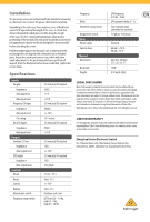
Power Connection
The 140 comes with the required power cable for connecting
to a standard Eurorack power supply system. Follow these
steps to connect power to the module. It is easier to make
these connections before the module has been mounted into
a rack case.
1.
Turn the power supply or rack case power off
and
disconnect the power cable.
2.
Insert the 16-pin connector on the power cable into the
socket on the power supply or rack case. The connector has
a tab that will align with the gap in the socket, so it cannot
be inserted incorrectly. If the power supply does not have
a keyed socket, be sure to orient pin 1 (-12 V) with the red
stripe on the cable.
3.
Insert the 10-pin connector into the socket on the back of
the module. The connector has a tab that will align with the
socket for correct orientation.
4.
After both ends of the power cable have been securely
attached, you may mount the module in a case and turn on
the power supply.
(1)
(3) (4) (5) (6)
(2)
(7)
(8)
(9)
(10)
(13)
(15)
(14)
(11)
(12)