Behringer 921 VOLTAGE CONTROLLED OSCILLATOR Quick Start Guide
Behringer 921 VOLTAGE CONTROLLED OSCILLATOR Manual
 |
View all Behringer 921 VOLTAGE CONTROLLED OSCILLATOR manuals
Add to My Manuals
Save this manual to your list of manuals |
Behringer 921 VOLTAGE CONTROLLED OSCILLATOR manual content summary:
- Behringer 921 VOLTAGE CONTROLLED OSCILLATOR | Quick Start Guide - Page 1
Quick Start Guide 921 VOLTAGE CONTROLLED OSCILLATOR Legendary Analog VCO Module for Eurorack Controls (1) (3) (2) (4) (5) (6) (9) (7) (8) (10) (12) (11) (13) (6) CNTRL IN - These summed jacks allow control voltage and modulation signals for the rectangular waveform to be routed in via - Behringer 921 VOLTAGE CONTROLLED OSCILLATOR | Quick Start Guide - Page 2
921 VOLTAGE CONTROLLED OSCILLATOR module's "octave scaling" to an exact 1 V/oct. calibration to facilitate precise control. 1. Power up the 921 V), 50 mA (-12 V) Quick Start Guide 3 LEGAL DISCLAIMER Music Tribe accepts no liability TC Electronic, TC Helicon, Behringer, Bugera, Auratone and Coolaudio - Behringer 921 VOLTAGE CONTROLLED OSCILLATOR | Quick Start Guide - Page 3
We Hear You
-
 1
1 -
 2
2 -
 3
3
 |
 |
Quick Start Guide
921 VOLTAGE
CONTROLLED OSCILLATOR
Legendary Analog VCO Module
for Eurorack
Controls
(4)
(5)
(6)
(3)
(8)
(7)
(2)
(9)
(10)
(11)
(1)
(13)
(12)
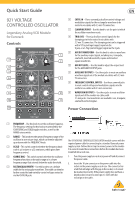
(1)
FREQUENCY
– Use this knob to set the oscillator frequency.
The frequency settings for this knob are controlled by the
COARSE RNG and SCALE toggle switches, as well as the
RANGE rotary switch.
(2)
RANGE
– This knob sets the general frequency range of the
oscillator in one-octave steps, which can then be adjusted
up or down with the FREQUENCY knob.
(3)
SCALE
– This switch controls whether the frequency knob
scale is ±6 octaves or ±12 semitones, which gives finer
frequency control.
(4)
COARSE RNG
– This switch controls whether the oscillator
frequency functions in the audio range or in a lower
frequency range that extends below the audio threshold.
(5)
RECTANGULAR WIDTH
– Use this knob to set a default
width for the rectangular waveform. The width can then be
further controlled and varied by control voltages routed in
via the CNTRL IN jacks.
(6)
CNTRL IN
– These summed jacks allow control voltage and
modulation signals for the rectangular waveform to be
routed in via cables with 3.5 mm TS connectors.
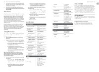
(7)
CLAMPING POINT
– Use this knob to set the point at which
the oscillator waveform resets.
(8)
TRIG (V/S)
– These jacks allow control signals for the
clamping point to be routed in via cables with
3.5 mm TS connectors. The clamping point can be triggered
with a V-Trig (voltage trigger) signal via the
V jack, or a S-Trig (switch trigger) signal via the S jack.
(9)
AUX OUT WAVEFORM
– Use this knob to select a waveform
for the auxiliary output signal, including sine, triangular,
sawtooth, inverted sawtooth, square and inverted
square waveforms.
(10)
AUX OUT LEVEL
– Use this knob to adjust the output level
for the AUXILIARY OUTPUT jacks.
(11)
AUXILIARY OUTPUTS
– Use these jacks to route an auxiliary
waveform signal out of the module via cables with 3.5 mm
TS connectors.
(12)
FREQUENCY CONTROL INPUTS
– Use these summed jacks
to route control voltage and modulation signals into the
oscillator via cables with 3.5 mm connectors.
(13)
WAVEFORM OUTPUTS
– Use these jacks to route oscillator
signals out of the module via cables with
3.5 mm jacks. Four waveforms are available: sine, triangular,
sawtooth and rectangular.
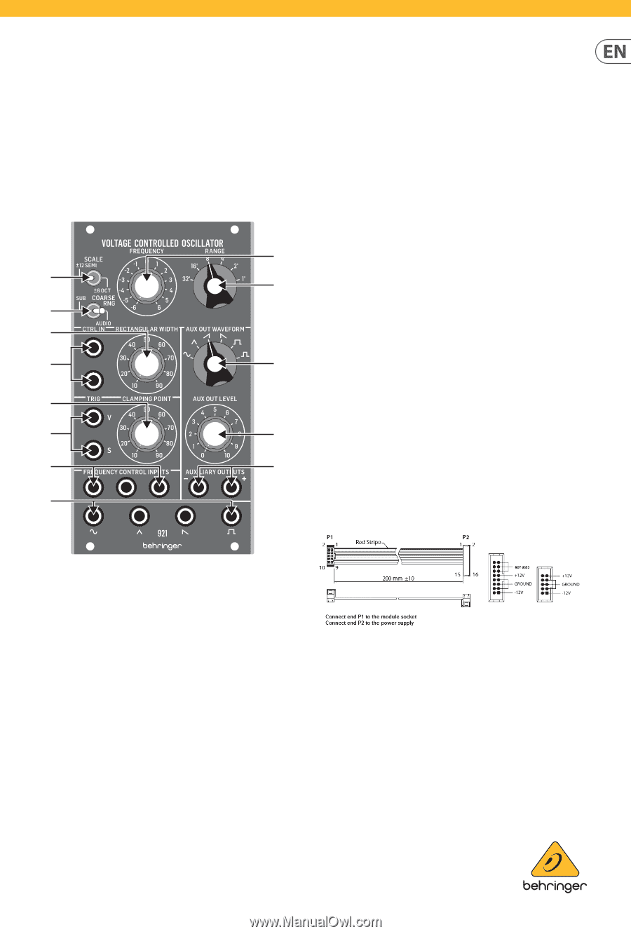
Power Connection
The 921 VOLTAGE CONTROLLED OSCILLATOR module comes with the
required power cable for connecting to a standard Eurorack power
supply system. Follow these steps to connect power to the module.
It is easier to make these connections before the module has been
mounted into a rack case.
1.
Turn the power supply or rack case power off and disconnect
the power cable.
2.
Insert the 16-pin connector on the power cable into the
socket on the power supply or rack case. The connector has
a tab that will align with the gap in the socket, so it cannot
be inserted incorrectly. If the power supply does not have a
keyed socket, be sure to orient pin 1 (-12 V) with the
red stripe on the cable.