Behringer 923 FILTERS Quick Start Guide
Behringer 923 FILTERS Manual
 |
View all Behringer 923 FILTERS manuals
Add to My Manuals
Save this manual to your list of manuals |
Behringer 923 FILTERS manual content summary:
- Behringer 923 FILTERS | Quick Start Guide - Page 1
Quick Start Guide 923 FILTERS Legendary Analog Dual Filter Module for Eurorack Controls Power Connection The 923 FILTERS module comes with the required power cable for connecting to a standard Eurorack power supply system. Follow these steps to connect power to the module. It - Behringer 923 FILTERS | Quick Start Guide - Page 2
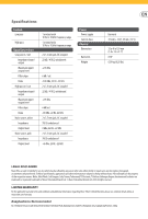
High pass Signal Connections Low pass in / out Impedance input / output Maximum input / output level Filter slope Noise High pass in / out Impedance input / output Maximum input / output level Filter slope Noise Noise source, white Impedance Output level Noise source, pink Impedance Output level
-
 1
1 -
 2
2
 |
 |
Quick Start Guide
923 FILTERS
Legendary Analog Dual Filter Module
for Eurorack
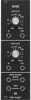
Controls
(1)
LOW PASS
– This knob controls the threshold or “cutoff”
frequency for the low pass filter. The low pass filter will
roll off all frequencies above this threshold frequency.
(2)
LOW PASS IN/OUT
– Route the incoming signal into the
low pass filter via the IN jack, and then send the outgoing,
filtered signal back out via the OUT jack. Connect the
incoming and outgoing signals by using cables with
3.5 mm TS connectors.
(3)
HIGH PASS
– This knob controls the threshold or “cutoff”
frequency for the high pass filter. The high pass filter will
roll off all frequencies below this threshold frequency.
(4)
HIGH PASS IN/OUT
– Route the incoming signal into the
high pass filter via the IN jack, and then send the outgoing,
filtered signal back out via the OUT jack. Connect the
incoming and outgoing signals by using cables with
3.5 mm TS connectors.
(5)
NOISE SOURCE/WHITE
– Use these parallel jacks to
send out a white noise signal via cables with 3.5 mm
TS connectors.
(6)
NOISE SOURCE/PINK
– Use these parallel jacks to
send out a pink noise signal via cables with 3.5 mm
TS connectors.
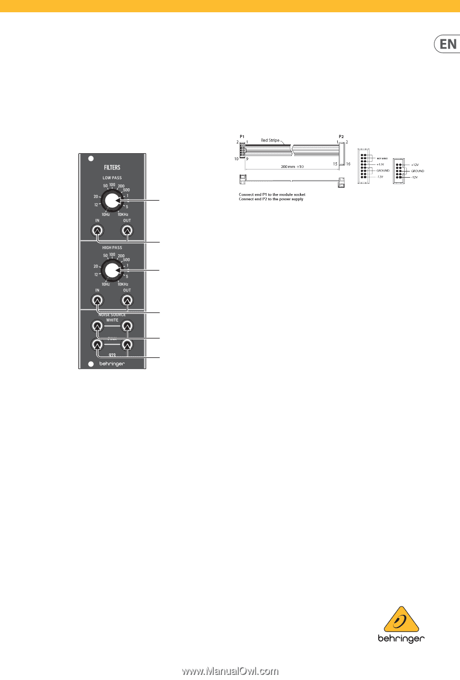
Power Connection
The 923 FILTERS module comes with the required power cable
for connecting to a standard Eurorack power supply system.
Follow these steps to connect power to the module. It is easier to
make these connections before the module has been mounted
into a rack case.
1.
Turn the power supply or rack case power off and
disconnect the power cable.
2.
Insert the 16-pin connector on the power cable into the
socket on the power supply or rack case. The connector has
a tab that will align with the gap in the socket, so it cannot
be inserted incorrectly. If the power supply does not have
a keyed socket, be sure to orient pin 1 (-12 V) with the red
stripe on the cable.
3.
Insert the 10-pin connector into the socket on the back of
the module. The connector has a tab that will align with the
socket for correct orientation.
4.
After both ends of the power cable have been
securely attached, you may mount the module in a case and
turn on the power supply.
Installation
The necessary screws are included with the module for mounting
in a Eurorack case. Connect the power cable before mounting.
Depending on the rack case, there may be a series of fixed holes
spaced 2 HP apart along the length of the case, or a track that
allows individual threaded plates to slide along the length
of the case. The free-moving threaded plates allow precise
positioning of the module, but each plate should be positioned
in the approximate relation to the mounting holes in your module
before attaching the screws.
Hold the module against the Eurorack rails so that each of the
mounting holes are aligned with a threaded rail or threaded plate.
Attach the screws part way to start, which will allow small
adjustments to the positioning while you get them all aligned.
After the final position has been established, tighten the
screws down.
(1)
(2)
(3)
(4)
(5)
(6)