Behringer 992 CONTROL VOLTAGES Quick Start Guide
Behringer 992 CONTROL VOLTAGES Manual
 |
View all Behringer 992 CONTROL VOLTAGES manuals
Add to My Manuals
Save this manual to your list of manuals |
Behringer 992 CONTROL VOLTAGES manual content summary:
- Behringer 992 CONTROL VOLTAGES | Quick Start Guide - Page 1
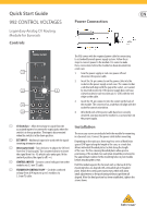
Quick Start Guide 992 CONTROL VOLTAGES Legendary Analog CV Routing Module for Eurorack Controls Power Connection The 992 comes with the required power cable for connecting to a standard Eurorack power supply system. Follow these steps to connect power to the module. It is - Behringer 992 CONTROL VOLTAGES | Quick Start Guide - Page 2
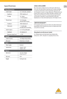
Impedance CV range External input Impedance Attenuation Control outputs Impedance Maximum output level Controls Control selectors Attenuator Power Power supply Current draw Physical Dimensions Rack units Weight 3 x 3.5 mm jacks, summed 100 kΩ unbalanced 1 V / octave, +/-10 V maximum 1 x 3.5 mm
-
 1
1 -
 2
2
 |
 |
Quick Start Guide
992 CONTROL VOLTAGES
Legendary Analog CV Routing
Module for Eurorack
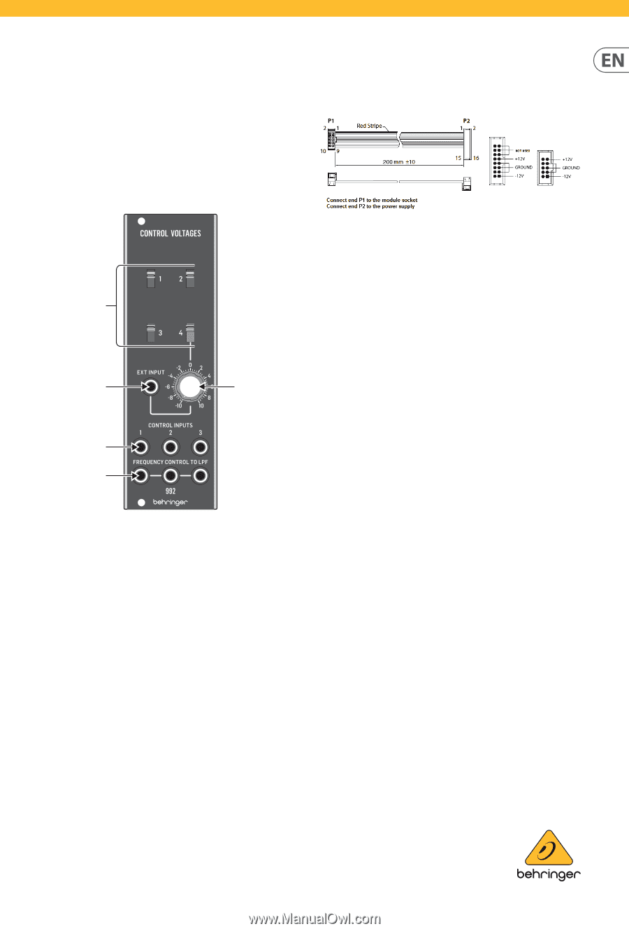
Controls
(1)
CV Switches
– Allow the voltage or signal from the
associated input to be sent to the output jacks when the
switch is in the up position. The input is disconnected
when the switch is in the down position.
(2)
EXT INPUT
– Additional input to be used with the signal-
inverting attenuator circuit.
(3)
Attenuator Knob
- Turn clockwise to adjust the CV level
from 0 to 10 (unity gain). Turn counterclockwise to invert
the signal from 0 to -10, which is also unity gain. At the
center 0 position, the signal is off (-∞).
(4)
CONTROL INPUTS
– Connect control voltages from other
modules via 3.5 mm TS cable.
(5)
FREQUENCY CONTROL TO LPF
– Send the combined
voltage from all 4 inputs to up to 3 modules via
3.5 mm TS cable.
Power Connection
The 992 comes with the required power cable for connecting
to a standard Eurorack power supply system. Follow these
steps to connect power to the module. It is easier to make
these connections before the module has been mounted into
a rack case.
1.
Turn the power supply or rack case power off and
disconnect the power cable.
2.
Insert the 16-pin connector on the power cable into the
socket on the power supply or rack case. The connector has
a tab that will align with the gap in the socket, so it cannot
be inserted incorrectly. If the power supply does not have
a keyed socket, be sure to orient pin 1 (-12 V) with the red
stripe on the cable.
3.
Insert the 10-pin connector into the socket on the back of
the module. The connector has a tab that will align with the
socket for correct orientation.
4.
After both ends of the power cable have been securely
attached, you may mount the module in a case and turn on
the power supply.
Installation
The necessary screws are included with the module for mounting
in a Eurorack case. Connect the power cable before mounting.
Depending on the rack case, there may be a series of fixed holes
spaced 2 HP apart along the length of the case, or a track that
allows individual threaded plates to slide along the length
of the case. The free-moving threaded plates allow precise
positioning of the module, but each plate should be positioned in
the approximate relation to the mounting holes in your module
before attaching the screws.
Hold the module against the Eurorack rails so that each of the
mounting holes are aligned with a threaded rail or threaded
plate. Attach the screws part way to start, which will allow
small adjustments to the positioning while you get them all
aligned. After the final position has been established, tighten the
screws down.
(1)
(4)
(5)
(2)
(3)