Behringer CLOCKED SEQUENTIAL CONTROL MODULE 1027 Quick Start Guide
Behringer CLOCKED SEQUENTIAL CONTROL MODULE 1027 Manual
 |
View all Behringer CLOCKED SEQUENTIAL CONTROL MODULE 1027 manuals
Add to My Manuals
Save this manual to your list of manuals |
Behringer CLOCKED SEQUENTIAL CONTROL MODULE 1027 manual content summary:
- Behringer CLOCKED SEQUENTIAL CONTROL MODULE 1027 | Quick Start Guide - Page 1
Quick Start Guide CLOCKED SEQUENTIAL CONTROL MODULE 1027 Legendary 2500 Series 8-Position Step Sequencer Module for Eurorack Controls (6) % PULSE WIDTH - Select between width settings for the rectangular waveform ranging from 5% to 95% duty cycle. The PULSE WIDTH control operates on the CLK OUT - Behringer CLOCKED SEQUENTIAL CONTROL MODULE 1027 | Quick Start Guide - Page 2
Connection Specifications The CLOCKED SEQUENTIAL CONTROL MODULE 1027 module comes with the required power cable for connecting to a standard Eurorack power supply system. Follow these steps to connect power to the module. It is easier to make these connections before the module has been mounted - Behringer CLOCKED SEQUENTIAL CONTROL MODULE 1027 | Quick Start Guide - Page 3
Position gates Type Impedance Maximum Output level Controls Rate % Pulse width Low / high Int / ext On / off Sequencer voltage knobs Step / reset Power Power supply Current draw Physical Dimensions Rack units Weight 8 x 3.5 mm
-
 1
1 -
 2
2 -
 3
3
 |
 |

CLOCKED SEQUENTIAL
CONTROL MODULE 1027
Legendary 2500 Series 8-Position Step
Sequencer Module for Eurorack
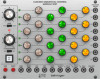
Controls
(1)
CH A / CH B / CH C SEQUENCER COLUMNS
– Use the
knobs to set the control voltage output for each step.
Each column sends out control voltages via that channel’s
respective CH A / CH B / CH C output jack.
(2)
STEP LEDs
– Each LED lights to indicate its respective
sequencer step is active.
(3)
POSITION GATES
– Each of these output jacks sends out a
gate signal for its respective sequence step via cables with
3.5 mm TS connectors. These 8 gate output signals are
also available via the 12-pin GATE OUT LINK CONNECTOR
located on the module underside. This 12-pin connector
can connect to and trigger other compatible modules,
such as the MIX-SEQUENCER MODULE 1050, via a 12-pin
ribbon connector.
(4)
RATE
– This knob controls the step speed at which the
sequencer moves from step to step. The knob operates
in two overall frequency ranges determined by the
LOW/HIGH switch.
(5)
LOW/HIGH
– Use this sliding switch to set whether the
RATE knob operates in a lower-frequency (LOW) or
higher-frequency (HIGH) range.
(6)
% PULSE WIDTH
– Select between width settings
for the rectangular waveform ranging from 5% to 95%
duty cycle. The PULSE WIDTH control operates on the
CLK OUT jack only, making this control very useful for
triggering other modules such as envelope generators,
and so on.
(7)
INT/EXT
– Use this switch to select between internal (INT)
or external (EXT) pulse width control voltage. When EXT
is selected, the % PULSE WIDTH control knob is disabled.
(8)
ON /OFF
– This button starts or stops the sequence with a
manual button push.
(9)
STEP
– Press this button to manually progress to the next
sequencer step.
(10)
RESET
– Press this button to manually restart the
sequence at step 1.
(11)
STEP
– Use this jack to route external trigger signals for
the STEP button into the module via cables with 3.5 mm
TS connectors.
(12)
RESET
– Use this jack to route external trigger signals for
the RESET button into the module via cables with 3.5 mm
TS connectors.
(13)
ON
– Use this jack to route external trigger signals to
enable the step counter into the module via cables with
3.5 mm TS connectors.
(14)
OFF
– Use this jack to route external trigger signals to
disable the step counter into the module via cables with
3.5 mm TS connectors.
(15)
RATE
– Use this jack to route in external control voltage
signals for the sequencer's step speed (usually controlled
by the RATE knob) via cables with 3.5 mm TS connectors.
(16)
WIDTH
– This jack allows control voltage and modulation
signals for the rectangular waveform to be routed in via
cables with 3.5 mm TS connectors.
(17)
CH A
– This jack sends out control voltage signals for
the CH A sequencer column via cables with 3.5 mm
TS connectors.
(18)
CH B
– This jack sends out control voltage signals for
the CH B sequencer column via cables with 3.5 mm
TS connectors.
(19)
CH C
– This jack sends out control voltage signals for
the CH C sequencer column via cables with 3.5 mm
TS connectors.
(20)
CLK OUT
– Use this jack to export the internally generated
clock signal via cables with 3.5 mm TS connectors.
The internal clock produces a gate pulse every time
the sequencer steps, and the gate pulse’s width can be
adjusted using the % PULSE WIDTH control or via the
WIDTH control jack.
(1)
(3)
(2)
(4)
(5)
(6)
(7)
(8)
(9)
(13) (14) (15) (16) (17)
(20)
(18)
(19)
(12)
(10)
(11)
V 1.0
Quick Start Guide