Behringer DUAL ENVELOPE GENERATOR MODULE 1033 Quick Start Guide
Behringer DUAL ENVELOPE GENERATOR MODULE 1033 Manual
 |
View all Behringer DUAL ENVELOPE GENERATOR MODULE 1033 manuals
Add to My Manuals
Save this manual to your list of manuals |
Behringer DUAL ENVELOPE GENERATOR MODULE 1033 manual content summary:
- Behringer DUAL ENVELOPE GENERATOR MODULE 1033 | Quick Start Guide - Page 1
Quick Start Guide DUAL ENVELOPE GENERATOR MODULE 1033 (7) TRIGGER MODE - Selects between single to re-trigger the envelope while a gate signal is present. Legendary 2500 Series Analog Envelope (8) MANUAL GATE - Press and hold to start the Generator Module for Eurorack envelope cycle. (9) GATE- - Behringer DUAL ENVELOPE GENERATOR MODULE 1033 | Quick Start Guide - Page 2
Type Impedance Max output level Out B Type Impedance Max output level Controls Gate delay Attack Initial decay Sustain Final decay Trigger modes Manual gate 3.5 mm TS jack, DC coupled >35 kΩ +4 V +12 V 3.5 mm TS jack, DC coupled >20 kΩ +4 V +12 V LIMITED WARRANTY For the applicable warranty terms
-
 1
1 -
 2
2
 |
 |

Quick Start Guide
DUAL ENVELOPE
GENERATOR MODULE 1033
Legendary 2500 Series Analog Envelope
Generator Module for Eurorack
Controls
(7)
(8)
(1) (2)
(3)
(4)
(5)
(6)
(9)
(10)
(11)
(12)
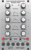
(1)
GATE DELAY
– Delays the envelope cycle up to 3 seconds
from initial gate input.
(2)
SIGNAL LED
– Indicates when a gate signal is present.
(3)
ATTACK TIME
– Adjusts the rate at which the envelope
reaches its peak voltage.
(4)
INITIAL DECAY TIME
– Adjusts the rate at which the
envelope decays from its peak to its designated
sustain level.
(5)
SUSTAIN LEVEL
– Controls the level at which the
envelope remains after its peak but before release,
sustaining as long as the input signal is present or the
manual gate button is held down.
(6)
FINAL DECAY TIME
– Controls how quickly the envelope
falls after the input signal stops or the manual gate button
is released.
(7)
TRIGGER MODE
– Selects between single mode,
where only the gate signal controls the envelope,
or multiple mode, which uses a positive trigger pulse to
re-trigger the envelope while a gate signal is present.
(8)
MANUAL GATE
– Press and hold to start the
envelope cycle.
(9)
GATE
– Connect a gate signal to control the envelope cycle.
(10)
TRIG
– Triggers a new attack of the envelope if a gate
signal is also present.
(11)
OUT L
– Send the left envelope positive and negative
control voltages to other modules via 3.5 mm TS cable.
(12)
OUT R
– Send the right envelope positive and negative
control voltages to other modules via 3.5 mm TS cable.
Power Connection
The unit comes with the required power cable for connecting
to a standard Eurorack power supply system. Follow these
steps to connect power to the module. It is easier to make these
connections before the module has been mounted into a
rack case.
1.
Turn the power supply or rack case power off and
disconnect the power cable.
2.
Insert the 16-pin connector on the power cable into the
socket on the power supply or rack case. The connector has
a tab that will align with the gap in the socket, so it cannot
be inserted incorrectly. If the power supply does not have
a keyed socket, be sure to orient pin 1 (-12 V) with the red
stripe on the cable.
3.
Insert the 10-pin connector into the socket on the back of
the module. The connector has a tab that will align with the
socket for correct orientation.
4.
After both ends of the power cable have been securely
attached, you may mount the module in a case and turn on
the power supply.
V 1.0