Behringer DUAL NOISE / RANDOM VOLTAGE GENERATOR MODULE 1016 Quick Start Guide
Behringer DUAL NOISE / RANDOM VOLTAGE GENERATOR MODULE 1016 Manual
 |
View all Behringer DUAL NOISE / RANDOM VOLTAGE GENERATOR MODULE 1016 manuals
Add to My Manuals
Save this manual to your list of manuals |
Behringer DUAL NOISE / RANDOM VOLTAGE GENERATOR MODULE 1016 manual content summary:
- Behringer DUAL NOISE / RANDOM VOLTAGE GENERATOR MODULE 1016 | Quick Start Guide - Page 1
Quick Start Guide DUAL NOISE / RANDOM VOLTAGE GENERATOR MODULE 1016 Legendary 2500 Series Dual Noise Source Module for Eurorack Controls (1) (2) (3) (4) (5) Power Connection The unit comes with the required - Behringer DUAL NOISE / RANDOM VOLTAGE GENERATOR MODULE 1016 | Quick Start Guide - Page 2
Installation The necessary screws are included with the module for mounting in a Eurorack case. Connect the power cable before mounting. Depending on the rack case, there may be a series of fixed holes spaced 2 HP apart along the length of the case, or a track that allows individual threaded plates
-
 1
1 -
 2
2
 |
 |

Quick Start Guide
DUAL NOISE / RANDOM
VOLTAGE GENERATOR
MODULE 1016
Legendary 2500 Series Dual Noise
Source Module for Eurorack
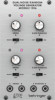
Controls
(1)
LEDs
– Indicate whether the associated knob is active.
(2)
NOISE knob
– Attenuates the output of the noise
generator.
(3)
SLOW RANDOM knob
– Attenuates the output of the
slow random voltage generator.
(4)
WHITE/PINK/OFF switch
– Selects between white or
pink noise, or disengage the output.
(5)
OFF/ON switch
– Engages or disengages the slow
random voltage output.
(6)
NOISE A/B
– Send the noise A and B signals to other
modules via 3.5 mm TS cable.
(7)
RANDOM A/B
– Send the random voltage signals to other
modules via 3.5 mm TS cable.
Power Connection
The unit comes with the required power cable for connecting
to a standard Eurorack power supply system. Follow these
steps to connect power to the module. It is easier to make
these connections before the module has been mounted into
a rack case.
1.
Turn the power supply or rack case power off and
disconnect the power cable.
2.
Insert the 16-pin connector on the power cable into the
socket on the power supply or rack case. The connector has
a tab that will align with the gap in the socket, so it cannot
be inserted incorrectly. If the power supply does not have
a keyed socket, be sure to orient pin 1 (-12 V) with the red
stripe on the cable.
3.
Insert the 10-pin connector into the socket on the back of
the module. The connector has a tab that will align with the
socket for correct orientation.
4.
After both ends of the power cable have been securely
attached, you may mount the module in a case and turn on
the power supply.
(1)
(2)
(3)
(4)
(5)
(6)
(7)
V 1.0