Behringer FILTAMP MODULE 1006 Quick Start Guide
Behringer FILTAMP MODULE 1006 Manual
 |
View all Behringer FILTAMP MODULE 1006 manuals
Add to My Manuals
Save this manual to your list of manuals |
Behringer FILTAMP MODULE 1006 manual content summary:
- Behringer FILTAMP MODULE 1006 | Quick Start Guide - Page 1
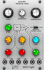
Quick Start Guide FILTAMP MODULE 1006 Legendary 2500 Series 24 dB Low-Pass VCF and VCA Module for Eurorack Controls (1) (2) (3) (4) (9) (5) (10 3. Insert the 10-pin connector into the socket on the back of the module. The connector has a tab that will align with the socket for correct orientation - Behringer FILTAMP MODULE 1006 | Quick Start Guide - Page 2
Installation The necessary screws are included with the module for mounting in a Eurorack case. Connect the power positioned in the approximate relation to the mounting holes in your module before attaching the screws. Hold the module against the Eurorack rails so that each of the mounting holes are
-
 1
1 -
 2
2
 |
 |

Quick Start Guide
FILTAMP MODULE 1006
Legendary 2500 Series 24 dB Low-Pass
VCF and VCA Module for Eurorack
Controls
(1)
FILTER
– Adjusts the cutoff frequency for the filter.
(2)
FILTER RESONANCE
– Boosts the resonance frequencies
selected with the Filter knob, potentially causing
VCF oscillation.
(3)
AMPLIFIER GAIN
– Controls the level of the VCA.
(4)
KEYBOARD knob
– Attenuate the voltage connected to
the KYBD input, which controls the cutoff frequency of
the filter.
(5)
IN B knob
– Adjusts the level of the signal connected to
the IN B input.
(6)
CV 2 to VCF knob
– Attenuate the voltage that is passed
from the CV 2 input to the VCF.
(7)
IN A knob
– Adjusts the level of the signal connected to
the IN A input.
(8)
CV 1 to VCF knob
– Attenuate the voltage that is passed
from the CV 1 input to the VCF.
(9)
EXPONENTIAL/LINEAR switch
– Select between a linear
or more natural exponential VCA response.
(10)
CV 2 to VCA knob
– Attenuate the voltage that is passed
from the CV 2 input to the VCA.
(11)
CV 1 to VCA knob
– Attenuate the voltage that is passed
from the CV 1 input to the VCA.
(12)
IN A
– Connect an input signal via 3.5 mm TS cable.
(13)
IN B
– Connect an input signal via 3.5 mm TS cable.
(14)
KYBD
– Connect a voltage that can be used to control the
VCF frequency.
(15)
CV 1
– Connect a voltage that can be used to control the
VCF frequency or VCA level.
(16)
CV 2
– Connect a voltage that can be used to control the
VCF frequency or VCA level.
(17)
OUT
– Send the processed signal to other modules via
3.5 mm TS cable.
Power Connection
The unit comes with the required power cable for connecting
to a standard Eurorack power supply system. Follow these
steps to connect power to the module. It is easier to make
these connections before the module has been mounted into
a rack case.
1.
Turn the power supply or rack case power off and
disconnect the power cable.
2.
Insert the 16-pin connector on the power cable into the
socket on the power supply or rack case. The connector has
a tab that will align with the gap in the socket, so it cannot
be inserted incorrectly. If the power supply does not have
a keyed socket, be sure to orient pin 1 (-12 V) with the red
stripe on the cable.
3.
Insert the 10-pin connector into the socket on the back of
the module. The connector has a tab that will align with the
socket for correct orientation.
4.
After both ends of the power cable have been securely
attached, you may mount the module in a case and turn on
the power supply.
(4)
(9)
(1)
(2)
(3)
(12)
(13)
(14)
(15)
(16)
(17)
(10)
(11)
(5)
(7)
(6)
(8)
V 1.0