Behringer XENYX X2222USB Manual - Page 13
Level Meter, LEVEL SETTING, PFL LEVEL SET, SOLO NORMAL, MAIN SOLO, PHONES jack, Subgroups and main - recording
 |
View all Behringer XENYX X2222USB manuals
Add to My Manuals
Save this manual to your list of manuals |
Page 13 highlights
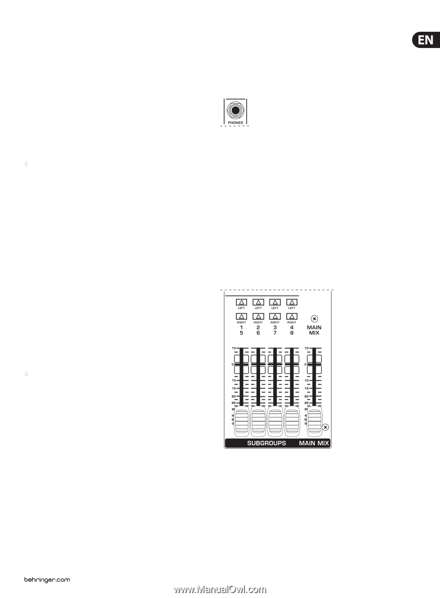
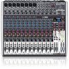
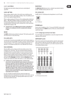
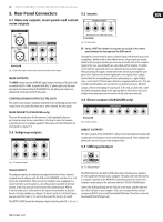
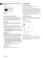
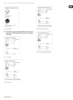
13 XENYX X2442USB/X2222USB/X1832USB/X1622USB User Manual 2.3.11 Level Meter The high-precision level meters always give you an accurate display of signal level. MAIN SOLO The MAIN SOLO LED lights up as soon as a channel or aux send solo switch is pressed. The MODE switch must be set to "Solo". LEVEL SETTING: PFL (LEVEL SET) When recording to digital recorders, the recorder's meter should not go into The PFL (LEVEL SET) LED indicates that the peak meter is set to PFL mode. overload. This is because, unlike analog recordings, it takes only slightly excessive levels to create unpleasant digital distortion. When recording to analog, the VU meters of the recording machine should reach approx. +3 dB with low-frequency signals (e.g. kick drum). Due to their inertia, VU meters tend to display too low a signal level at frequencies above 1 kHz. You should only drive instruments such as a Hi-Hat as far as -10 dB. Snare drums should be driven to approx. 0 dB. ◊ The peak meters of your XENYX display level almost independent of frequency. A recording level of 0 dB is recommended for all types of signal. Fig. 2.17: PHONES jack PHONES jack You can connect headphones to this ¼" stereo jack (X2442USB: 2 phones jacks). The signal routed to the PHONES connection is the same as that routed to the control room output. MODE The MODE switch determines whether the channels' SOLO switch operates as PFL (Pre Fader Listen) or as solo (Solo In Place). 2.3.12 Subgroups and main mix fader You use the high-precision quality faders to control the output level of the subgroups and the main mix. PFL (LEVEL SET) To activate the PFL function, press the MODE switch. The PFL function should, as a rule, be used for level setting (GAIN). The signal is sourced pre-fader and assigned to the mono PFL bus. In "PFL" mode, only the left side of the peak meter is in operation. A PFL'd channel should be driven to the 0 dB mark of the VU meter. LEFT/RIGHT switch The switches located above the subgroup faders assign the subgroup signal either to the left or right side of the main bus. Similarly, it can be routed to both sides or none at all. In the latter case, the submix is present only at the corresponding subgroup outputs. SOLO (NORMAL) When the MODE switch is not depressed, the stereo solo bus is active. Solo is actually short for "Solo In Place". This is the customary method for listening to an individual signal or to a group of signals. As soon as a solo switch is pressed, all channels not solo selected are muted in th e monitor path (control room and phones). A channel's position in the stereo image is maintained. The solo bus carries the output signals of the channel pan controls, the aux sends and the stereo line inputs. On the X2442USB all aux returns, and on the X1832USB only aux return 2 can be routed to the solo bus. The solo bus is, as a rule, taken post-fader. ◊ The PAN control in the channel strip offers a constant power characteristic. This means that the signal is always at a constant level, irrespective of position in the stereo panorama. If the PAN control is moved fully left or right, the level in that channel increases by 4 dB. This ensures that, when set at the center of the stereo image, the audio signal does not appear louder. For this reason, with the solo function activated (Solo in Place), audio signals from channels with PAN controls that have not been moved fully left or right are displayed at a lower volume than in the PFL function. As a rule, solo signals are monitored via the control room outputs and headphones jack and are displayed by the level meters. If a solo switch is pressed, the signals from the tape input, the subgroups and the main mix are cut from these outputs and the level meter. X2442USB Fig. 2.18: Subgroup and main mix fader
-
 1
1 -
2
-
3
-
4
-
5
-
6
-
7
-
 8
8 -
 9
9 -
 10
10 -
 11
11 -
 12
12 -
 13
13 -
 14
14 -
 15
15 -
 16
16 -
 17
17 -
 18
18 -
19
-
20
-
21
 |
 |