Behringer XENYX X2222USB Manual - Page 16
Installation - mixer manual
 |
View all Behringer XENYX X2222USB manuals
Add to My Manuals
Save this manual to your list of manuals |
Page 16 highlights
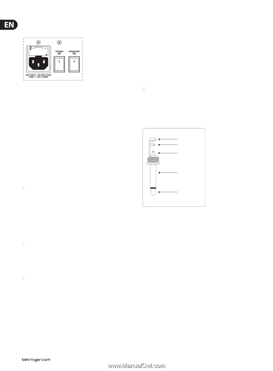
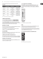
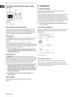
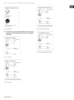
16 XENYX X2442USB/X2222USB/X1832USB/X1622USB User Manual 5.6 Voltage supply, phantom power supply and fuse All Models Fig. 5.6: Voltage supply and fuse 6. Installation 6.1 Rack mounting The packaging of your mixing console contains two 19" rack mounts for installation on the side panels of the console. Before you can attach the rack mounts to the mixing console, you need to remove the screws holding the left and right side panels. Then, use these screws to fasten the two rack mounts, each specifically to one side. With the rack mounts installed, you can mount the mixing console in a commercially available 19" rack. Be sure to allow for proper air flow around the unit, and do not place the mixing console close to radiators or power amps, so as to avoid overheating. ◊ Only use the screws holding the mixing console side panels to fasten the 19" rack mounts. FUSE HOLDER/IEC MAINS RECEPTACLE 6.2 Cable connections The console is connected to the mains via the cable supplied, which meets the required safety standards. Blown fuses must only be replaced by fuses of the same type and rating. The mains connection is made via a cable with IEC mains connector. An appropriate mains cable is supplied with the equipment. POWER switch Use the POWER switch to turn on the mixing console. The POWER switch should always be in the "Off" position when you are about to connect your unit to the mains. You will need a large number of cables for the various connections of the console. The illustrations below show the wiring of these cables. Be sure to use only high-grade cables. ¼" TS footswitch connector strain relief clamp sleeve tip To disconnect the unit from the mains, pull out the main cord plug. When installing the product, ensure that the plug is easily accessible. If mounting in a rack, ensure that the mains can be easily disconnected by a plug pull or by an all-pole disconnect switch on or near the rack. sleeve pole 1/ground ◊ Attention: The POWER switch does not fully disconnect the unit from the mains. Unplug the power cord completely when the unit is not used for prolonged periods of time. tip pole 2 The footswitch connects both poles momentarily PHANTOM switch The PHANTOM switch activates the phantom power (necessary to operate condenser microphones) on the XLR sockets of the mono channels. The red +48 V LED illuminates when phantom power is on. As a rule, dynamic microphones can still be used with phantom power, provided that they are wired in a balanced configuration. In case of doubt, contact the microphone manufacturer! ◊ Connect microphones before you switch on the phantom power supply. Please do not connect microphones to the mixer (or the stagebox/ wallbox) while the phantom power supply is switched on. In addition, the monitor/PA loud-speakers should be muted before you activate the phantom power supply. After switching on, wait approx. one minute to allow for system stabilization. Fig. 6.1: Foot switch connector 6.2.1 Audio connections Please use commercial RCA cables to wire the 2-track inputs and outputs. You can, of course, also connect unbalanced devices to the balanced input/ outputs. Use either mono plugs, or use stereo plugs to link the ring and shaft (or pins 1 & 3 in the case of XLR connectors). ◊ Caution! Please also note the information given in chapter 6.2.1 "Audio connections". SERIAL NUMBER Please note the important information on the serial number given in chapter 1.3.3.
-
 1
1 -
2
-
3
-
4
-
5
-
6
-
7
-
8
-
9
-
10
-
 11
11 -
 12
12 -
 13
13 -
 14
14 -
 15
15 -
 16
16 -
 17
17 -
 18
18 -
 19
19 -
 20
20 -
 21
21
 |
 |