Behringer XENYX X2222USB Manual - Page 7
LINE IN, INSERT, LOW CUT, COMPRESSOR, Equalizer, Monitor and effects busses Aux Sends - used
 |
View all Behringer XENYX X2222USB manuals
Add to My Manuals
Save this manual to your list of manuals |
Page 7 highlights
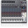
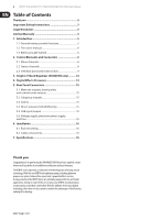
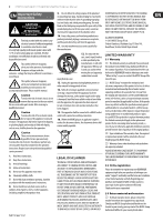
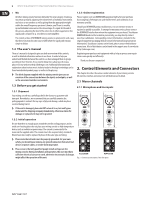
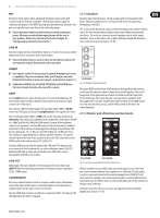
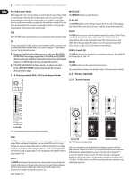
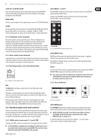
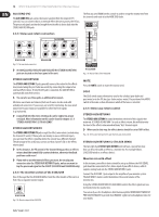
7 XENYX X2442USB/X2222USB/X1832USB/X1622USB User Manual MIC Each mono input channel offers a balanced microphone input via the XLR connector and also features switchable +48 V phantom power supply for condenser microphones. The XENYX preamps provide undistorted and noise-free gain as is typically known only from costly outboard preamps. ◊ Please mute your monitor system before you switch on phantom power. Otherwise potentially damaging thumps will be sent to your speakers. Please also note the instructions in chapter 5.5 "Voltage supply, phantom power and fuse". 2.1.2 Equalizer All mono input channels have a 3-band equalizer with semi-parametric mid bands. All bands provide boost or cut of up to15 dB. In the central position, the equalizer is off (flat). The circuitry of the British EQs is based on the technology used in the best-known top-of-the-line consoles and providing a warm sound without any unwanted side effects. The result are extremely musical equalizers which, unlike simple equalizers, cause no side effects such as phase shifting or bandwidth limitation, even with extreme gain settings of ±15 dB. LINE IN Each mono input also has a balanced line input on a ¼" jack. You can also connect unbalanced devices using mono jacks to these inputs. ◊ Please remember that you can use either the microphone input or the line input of a channel, but not both at the same time! INSERT ◊ Insert points enable the processing of a signal with dynamic processors or equalizers. They are sourced pre-fader, pre-EQ and pre-aux send. Detailed information on using insert points can be found in chapter 5.3. ◊ Unlike the X2442USB, the X1622USB, X1832USB and X2222USB have their insert points located on the rear of the console. GAIN Use the GAIN control to adjust the input gain. This control should always be turned fully counter-clockwise whenever you connect or disconnect a signal source to one of the inputs. The scale has 2 different value ranges: the first value range (+10 to +60 dB) refers to the MIC input and shows the amplification for the signals fed in there. The second value range (+10 to -40 dB) refers to the line input and shows its sensitivity. The settings for equipment with st andard line-level signals (-10 dBV or +4 dBu) look like this: While the GAIN control is turned all the way down, connect your equipment. Set the GAIN control to the external devices' standard output level. If that unit has an output signal level display, it should show 0 dB during signal peaks. For +4 dBu, turn up GAIN slightly, for -10 dBV a bit more. Fine-tuning of a signal being fed in is done using the level meter. To route the channel signal to the level meter, you have to press the SOLO switch and set the MODE switch in the main section to PFL (LEVEL SET). All Models Fig. 2.2: Equalizer of the input channels The upper (HIGH) and the lower (LOW) bands are shelving filters that increase or decrease all frequencies above or below their cut-off frequency. The cut-off frequencies of the upper and lower bands are 12 kHz and 80 Hz respectively. For the mid range, the console features a semi-parametric equalizer with a filter quality (Q) of 1 octave, tunable from 100 Hz to 8 kHz. Use the MID control to set the amount of boost or cut, and the FREQ control to determine the central frequency. 2.1.3 Monitor and effects busses (Aux Sends) Using the GAIN control, drive the signal to the 0-dB mark. This way you have a vast amount of drive headroom for use with very dynamic signals. The CLIP display should light up only rarely, preferably never. While fine-tuning, the equalizer should be set to neutral. LOW CUT Additionally, the mono channels of the mixing consoles have a high-slope LOW CUT filter for eliminating unwanted, low-frequency signal components (75 Hz, 18 dB/octave). COMPRESSOR Each mono channel features a built-in compressor which lowers the dynamic range of the signal and increases its perceived loudness. The loud peaks are squashed down and the quiet sections are boosted. Turn the COMP knob clockwise to add more compression effect. The adjacent LED with light when the effect is engaged. X1622USB X2442USB Fig. 2.3: Aux Send control MON and FX in the channel strips Monitor and effects busses (AUX sends) source their signals via a control from one or more channels and sum these signals to a so-called bus. This bus signal is sent to an aux send connector (for monitoring applications: MON OUT) and then routed, for example, to an active monitor speaker or external effects device. In the latter case, the effects return can then be brought back into the console via the aux return connectors. All monitor and effects busses are mono, are tapped into post EQ and offer amplification of up to +15 dB.
-
 1
1 -
 2
2 -
 3
3 -
 4
4 -
 5
5 -
 6
6 -
 7
7 -
 8
8 -
 9
9 -
 10
10 -
 11
11 -
 12
12 -
13
-
14
-
15
-
16
-
17
-
18
-
19
-
20
-
21
 |
 |