Behringer XENYX X2222USB Manual - Page 8
Stereo channels - case
 |
View all Behringer XENYX X2222USB manuals
Add to My Manuals
Save this manual to your list of manuals |
Page 8 highlights
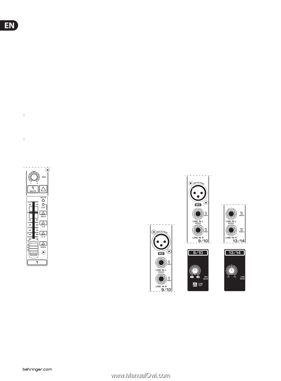
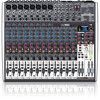
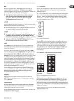
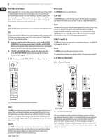
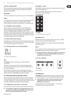
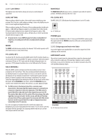
8 XENYX X2442USB/X2222USB/X1832USB/X1622USB User Manual Pre-fader/post-fader When using effects on a channel signal, it is usual to have the aux send post fader so that the balance between effect and dry signal stays constant even when the channel fader is altered. If this were not the case, the effects signal of the channel would remain audible even when the channel fader is turned all the way down. For monitoring, the aux sends are generally pre-fader, i.e. they operate independently of the position of the channel fader. PRE When the PRE switch is pressed down, the associated aux send is taken pre-fader. FX The aux send marked FX offers a direct route to the built-in effects processor and is therefore post-fader and post-mute. Please refer to chapter 4 "Digital Effects Processor" for detailed information. ◊ If you are using the built-in effects processor, make sure that STEREO AUX RETURN 3 has nothing plugged into it (X2442USB and X2222USB), otherwise the internal effects return will be muted. This is not relevant if you use the FX OUT jack to drive an external effects device. ◊ X1622USB and X1832USB: On these consoles, the above note refers to the STEREO AUX RETURN 2 jacks as these models do not have a dedicated effect output. 2.1.4 Routing switch, PAN, SOLO and channel fader MUTE LED The MUTE LED indicates a muted channel. CLIP-LED The CLIP-LED lights up when the input signal is driven too high. If this happens, back off the GAIN control and, if necessary, check the setting of the channel EQ. SOLO The SOLO switch is used to route the channel signal to the solo bus (Solo In Place) or to the PFL bus (Pre Fader Listen). This enables you to listen to a channel signal without affecting the main output signal. The signal you hear is taken either before the pan control (PFL, mono) or after the pan and channel fader (Solo, stereo) (cf. chap. 2.3.10 "Level meters and monitoring"). SUB (1-2 and 3-4) The SUB switch routes the signal to the corresponding subgroups. The X2442USB has 4 subgroups (1-2 and 3-4). MAIN The MAIN switch routes the signal to the main mix bus. The channel fader determines the channel's volume in the main mix (or submix). 2.2 Stereo channels 2.2.1 Channel inputs X2442USB Fig. 2.4: The panorama and routing controls and the channel fader PAN The PAN control determines the position of the channel signal within the stereo image. When working with subgroups, you can use the PAN control to assign the signal to just one output, which gives you additional flexibility in recording situations. For example, when routing to subgroups 3 and 4, panning hard left will route the signal to group output 3 only, and panning hard right will route to group output 4 only. MUTE The MUTE switch breaks the signal path pre-channel fader, hence muting that channel in the main mix. The aux sends which are set to post-fader are likewise muted for that channel, while the pre-fader monitor paths remain active irrespective of whether the channel is muted or not. X2222USB X2442USB Fig. 2.5: The various stereo channel inputs XENYX2442FX Each stereo channel has two balanced line level inputs on jacks for left and right channels. Channels 9/10 and 11/12 on the X2442USB feature an additional XLR microphone jack with phantom power. If only the left jack (marked "L") is used, the channel operates in mono. The stereo channels are designed to handle typical line level signals, and, depending on model, have a level switch (+4 dBu or -10 dBV) and/or a line GAIN control. Both jack inputs will also accept unbalanced connectors.
-
 1
1 -
2
-
 3
3 -
 4
4 -
 5
5 -
 6
6 -
 7
7 -
 8
8 -
 9
9 -
 10
10 -
 11
11 -
 12
12 -
 13
13 -
14
-
15
-
16
-
17
-
18
-
19
-
20
-
21
 |
 |