Benelli Super Vinci Quick Assembly Guide
Benelli Super Vinci Manual
 |
View all Benelli Super Vinci manuals
Add to My Manuals
Save this manual to your list of manuals |
Benelli Super Vinci manual content summary:
- Benelli Super Vinci | Quick Assembly Guide - Page 1
-to-assemble shotgun in the world. Follow these 3 easy steps to assemble the Vinci. NOTE: No exessive force is required during assembly if all parts are properly aligned. STEP 1: Line up the white dot on the 1 quadrafIT™ buttstock Module with the sighting groove on the top of the 2 Barrel/Receiver
-
 1
1
 |
 |
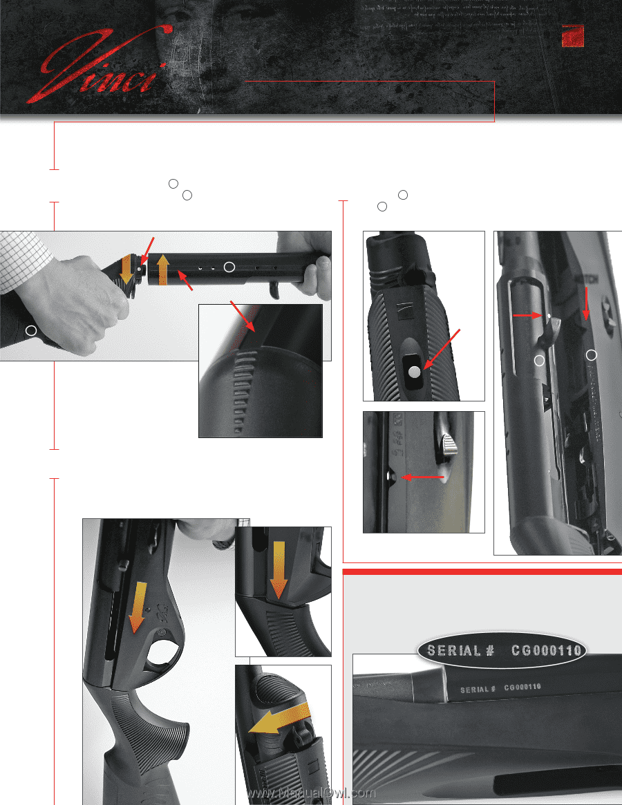
STEP 1:
Congratulations on the purchase of your new Benelli Vinci; the most reliable, fastest shooting, softest kicking,
lightweight and easiest-to-assemble shotgun in the world.
Follow these 3 easy steps to assemble the Vinci.
IT’S AS EASY AS 1, 2, 3!
QUICK ASSEMBLY GUIDE
STEP 2:
STEP 3:
When rotation is complete,
sighting groove on the
BARREL/RECEIVER MODULE
and
raised triangular markings on the
QUADRAFIT
™
BUTTSTOCK MODULE
will align.
(Fig. B)
The view when notch and dot are
properly alligned.
(Fig. E)
Fig. G
Fig. H
Line up the white dot on the
QUADRAFIT
™
BUTTSTOCK MODULE
with the
sighting groove on the top of the
BARREL/RECEIVER MODULE
.
Insert the
QUADRAFIT
™
BUTTSTOCK MODULE
into the
BARREL/RECEIVER MODULE
and twist in a clockwise direction. (Fig. A)
Firmly push down on the
TRIGGER GROUP/FOREARM MODULE
(Fig. F)
until flush with the
QUADRAFIT
™
BUTTSTOCK MODULE
so that no gap
between the two modules exist. (Fig. G) While maintaining downward pressure,
turn magazine cap clockwise until the white dot on the
TRIGGER GROUP/
FOREARM MODULE
is no longer visible (Fig. H).
IMPORTANT SERIAL NUMBER INFORMATION:
Fig. I
The ATF recognizes the number on the
BARREL/RECEIVER MODULE
(Fig. I) as
the legally recorded serial number.
Numbers located on the
TRIGGER GROUP/
FOREARM MODULE
do not comply with U.S. firearms laws and regulations.
1
2
Fig. F
2
1
NOTE: NO EXESSIVE FORCE IS REQUIRED DURING ASSEMBLY IF ALL PARTS ARE PROPERLY ALIGNED.
Fig. A
sighting groove
Fig. B
Fig. C
NOTCH
2
3
Fig. D
With the white dot on the magazine tube visible (Fig. C) align the notch
on the
TRIGGER GROUP/FOREARM MODULE
to the white dot on the
BARREL/RECEIVER MODULE.
(Fig. D)
2
3
Fig. E