Biostar G41-M7 Setup Manual - Page 5
Rear Panel Connectors - cpu support
 |
View all Biostar G41-M7 manuals
Add to My Manuals
Save this manual to your list of manuals |
Page 5 highlights
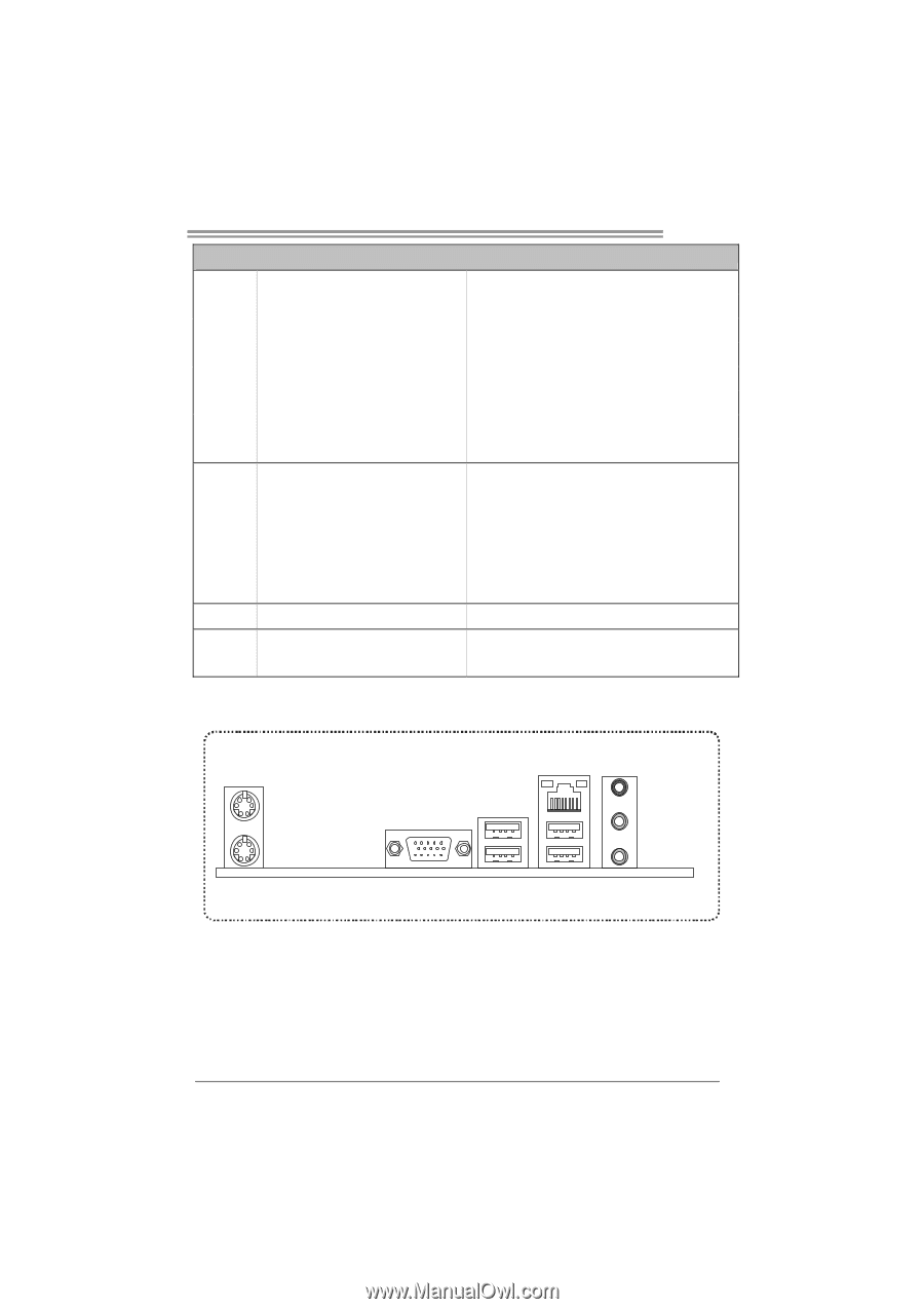
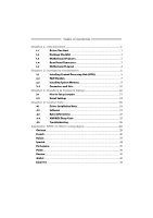
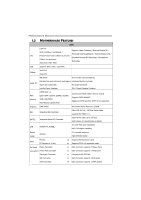
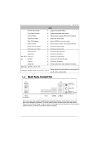
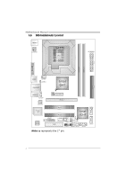
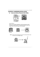
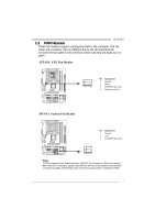
G41-M7 SPEC Front Panel Connector x1 Supports front panel facilities Front Audio Connector x1 Supports front panel audio function CPU Fan Header x1 CPU Fan power supply (with Smart Fan function) System Fan Header x1 System Fan Power supply Clear CMOS Header x1 Restore CMOS data to factory default USB Connector x2 Each connector supports 2 front panel USB ports Power Connector (24pin) x1 Connects to Power supply Power Connector (4pin) x1 Connects to Power supply PS/2 Keyboard PS/2 Mouse Back Panel VGA port I/O LAN port USB Port Audio Jack x1 Connects to PS/2 Keyboard x1 Connects to PS/2 Mouse x1 Connect to D-SUB monitor x1 Connect to RJ-45 ethernet cable x4 Connect to USB devices x3 Provide Audio-In/Out and microphone connection Board Size 182 (W) x 235 (L) mm Biostar reserves the right to add or remove support for OS Support Windows 2000 / XP / Vista 32 / Vista 64 any OS with or without notice 1.4 REAR PANEL CONNECTORS PS/ 2 Mouse PS/2 Keyboard LAN VGA USBX2 USBX2 Line In/ Surround Line Out Mic In 1/ Bass/ Center Since the audio chip supports High Definition Audio Specification, the function of each audio jack can be defined by software. The input / output function of each audio jack listed above represents the default setting. However, when connecting external microphone to the audio port, please use the Line In (blue) and Mic In (Pink) audio jack. 3
-
 1
1 -
 2
2 -
 3
3 -
 4
4 -
 5
5 -
 6
6 -
 7
7 -
 8
8 -
 9
9 -
 10
10 -
 11
11 -
12
-
13
-
14
-
15
-
16
-
17
-
18
-
19
-
20
-
21
-
22
-
23
-
24
-
25
-
26
-
27
-
28
-
29
-
30
-
31
-
32
-
33
-
34
-
35
-
36
-
37
-
38
-
39
-
40
-
41
-
42
-
43
-
44
-
45
-
46
-
47
 |
 |