Biostar H55A Setup Manual
Biostar H55A Manual
 |
View all Biostar H55A manuals
Add to My Manuals
Save this manual to your list of manuals |
Biostar H55A manual content summary:
- Biostar H55A | Setup Manual - Page 1
H55A+ Setup Manual FCC Information and Copyright This equipment has been tested not installed and used in accordance with the instructions, may cause harmful interference to radio communications. in writing. The content of this user's manual is subject to be changed without notice and we will - Biostar H55A | Setup Manual - Page 2
Memory 8 2.4 Connectors and Slots 10 Chapter 3: Headers & Jumpers Setup 13 3.1 How to Setup Jumpers 13 3.2 Detail Settings 13 Chapter 4: Useful Help 18 4.1 Driver Installation Note 18 4.2 Software 19 4.3 Extra Information 23 4.4 AMI BIOS Beep Code 25 4.5 Troubleshooting - Biostar H55A | Setup Manual - Page 3
. 1.2 PACKAGE CHECKLIST Serial ATA Cable X 2 Rear I/O Panel for ATX Case X 1 User's Manual X 1 Fully Setup Driver CD X 1 FDD Cable X 1 (optional) USB 2.0 Cable X1 (optional) Serial ATA Power Cable X 1 (optional) Note: The package contents may be different due to area or your motherboard version. 1 - Biostar H55A | Setup Manual - Page 4
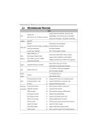
Motherboard Manual 1.3 MOTHERBOARD FEATURES SPEC Supports Execute Disable Bit / Enhanced Intel Socket 1156 CPU SpeedStep® / Intel Architecture-64 / Extended Intel Core i7 / i5 / i3/ Pentium processor Memory 64 Technology / Virtualization Technology Chipset Intel H55 ITE 8721 Environment - Biostar H55A | Setup Manual - Page 5
IR Connector Power Connector (24pin) Power Connector (4pin) PS/2 Keyboard / Mouse HDMI Port Back Panel I/O VGA Port DVI-D Port LAN Port USB Port Audio Jack Board Size 225(W) x 295 (L) mm OS Support Windows XP / Vista / 7 H55A+ SPEC x1 Supports infrared function x1 Connects to Power supply - Biostar H55A | Setup Manual - Page 6
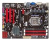
Motherboard Manual 1.5 MOTHERBOARD LAYOUT USBKB1 ATXPWR2 CPU_FAN1 HDMI1 DVI 1 Socket 1156 CP U 1 DDR3_ A2 DDR3_ A1 DDR3_ B2 DDR3_ B1 VGA1 JUSBV1 RJ45USB1 AUDIO1 F_AUDIO1 SYS_FAN2 PEX1_1 PEX 16_1 LAN ATXPWR1 H55 PEX 16_2 CODEC Super I/O JSPD IF OU T 1 J_PRINT1 PCI1 PCI2 JUS BV2 - Biostar H55A | Setup Manual - Page 7
CHAPTER 2: HARDWARE INSTALLATION 2.1 INSTALLING CENTRAL PROCESSING UNIT (CPU) H55A+ Special Notice: Remove Pin Cap before installation, and make good preservation for future use. When the CPU is removed, cover the Pin Cap on the empty socket to ensure pin legs won't be damaged. Step 1: Pull the - Biostar H55A | Setup Manual - Page 8
Motherboard Manual Step 3: Look for the triangular cut edge on socket, and the golden dot on CPU should point forwards this triangular cut edge. The CPU will fit only in the correct orientation. Step 4: Hold the CPU down firmly, and then lower the lever to locked position to complete the - Biostar H55A | Setup Manual - Page 9
H55A+ 2.2 FAN HEADERS These fan headers support cooling-fans built in the computer. The fan cable and connector may be different due to the fan manufacturer. Connect the fan cable to the connector while matching the black wire to pin#1. CPU_FAN1: CPU Fan Header 4 1 Pin Assignment 1 Ground 2 Power - Biostar H55A | Setup Manual - Page 10
DDR3_A2 DDR3_A1 DDR3_B2 DDR3_B1 Motherboard Manual 2.3 INSTALLING SYSTEM MEMORY A. DDR3 module 1. Unlock a DIMM slot by pressing the retaining clips outward. Align a DIMM on the slot such that the notch on the DIMM matches the - Biostar H55A | Setup Manual - Page 11
Capacity DIMM Socket Location DDR3_A2 DDR3_A1 DDR3_B2 DDR3_B1 DDR3 Module 512MB/1GB/2GB/4GB 512MB/1GB/2GB/4GB 512MB/1GB/2GB/4GB 512MB/1GB/2GB/4GB H55A+ Total Memory Size Max is 16GB. C. Dual Channel Memory Installation Please refer to the following requirements to activate Dual Channel function - Biostar H55A | Setup Manual - Page 12
The motherboard has a PCI to SATA Controller with 6channels SATA interface, it satisfies the SATA 2.0 spec and with transfer rate of 3Gb/s. SATA2 SATA1 SATA4 SATA3 SATA6 SATA5 Pin Assignment 1 Ground 2 TX+ 3 TX4 Ground 5 RX6 RX+ 7 Ground 14 7 ATXPWR1: ATX Power Source Connector This connector is - Biostar H55A | Setup Manual - Page 13
+12V to CPU power circuit. 1 4 H55A+ 23 Pin Assignment 1 +12V 2 +12V 3 Ground 4 Ground Note: Before you power on the system, please make sure that both ATXPWR1 and ATXPWR2 connectors have been plugged-in. PCI1/PCI2: Peripheral Component Interconnect Slots This motherboard is equipped - Biostar H55A | Setup Manual - Page 14
Motherboard Manual PEX16_1: PCI-Express Gen2 x16 Slot - PCI-Express 2.0 compliant. - Maximum theoretical realized bandwidth of 8GB/s simultaneously per direction, for an aggregate of 16GB/s totally. - PCI-Express Gen2 supports a raw bit-rate of 5.0Gb/s on the data pins. PEX16_2: PCI-Express Gen2 x4 - Biostar H55A | Setup Manual - Page 15
". Pin opened Pin closed 3.2 DETAIL SETTINGS Pin1-2 closed PANEL1: Front Panel Header This 16-pin connector includes Power-on, Reset, HDD LED, Power LED, and speaker connection. It allows user to connect the PC case's front panel switch functions. POW _LED On/ Off ++ - 9 16 1 8 +- SPK - Biostar H55A | Setup Manual - Page 16
Motherboard Manual F_USB1/F_USB2/F_USB3: Headers for USB 2.0 Ports at Front Panel This motherboard provides 3 USB 2.0 headers, which allows user to connect additional USB cable on the PC front panel, and also can be connected with internal USB devices, like USB card reader. F_USB3 F_USB1 F_ USB2 - Biostar H55A | Setup Manual - Page 17
H55A+ F_AUDIO1: Front Panel Audio Header This header allows user to connect the front audio output cable with the PC front panel. This header allows only HD audio front panel connector, not AC'97. 10 9 2 1 Pin Assignment 1 Mic Left in 2 Ground 3 Mic Right in 4 GPIO 5 Right line in 6 Jack Sense - Biostar H55A | Setup Manual - Page 18
Motherboard Manual J_PRINT1: Printer Port Connector This header allows you to connector printer on the PC. Pin Assignment 1 -Strobe 2 -ALF 3 Data 0 4 -Error 5 Data 1 6 -Init 7 Data 2 8 -Scltin 9 Data 3 10 Ground 11 Data 4 12 Ground 13 Data 5 2 26 1 25 - Biostar H55A | Setup Manual - Page 19
on pin2-3 allows user to restore the BIOS safe setting and the CMOS data. Please carefully follow the procedures to avoid damaging the motherboard. 13 Pin 1-2 Close: Normal Operation (Default). 13 13 Pin 2-3 Close: Clear CMOS data. ※ Clear CMOS Procedures: 1. Remove AC power line. 2. Set the - Biostar H55A | Setup Manual - Page 20
better system performance. You will see the following window after you insert the CD The setup guide will auto detect your motherboard and operating system. Note: If this window didn't show up after you insert the Driver CD, please use file browser to locate and execute the file SETUP.EXE under your - Biostar H55A | Setup Manual - Page 21
Line" / "BIOS Update" appears on the desktop. Double-click the icon to launch the utility. eHot-Line (Optional) eHot-Line is a convenient utility that helps you to contact with our Tech-Support system. This utility will collect the system information which is useful for analyzing the problem you - Biostar H55A | Setup Manual - Page 22
Motherboard Manual motherboard/BIOS/CPU/ service. If you are not using Outlook Express as your default e-mail client application, you may need to save the system information to a .txt file and send the file to our tech support with other e-mail application. Go to the following web http://www.biostar - Biostar H55A | Setup Manual - Page 23
H55A+ BIOS Update BIOS Update is a convenient utility which allows you to update your motherboard BIOS under Windows system. AWARD BIOS Show current BIOS information AMI BIOS Clear CMOS function (Only for AWARD BIOS) Save current BIOS to a .bin file Update BIOS with a BIOS file - Biostar H55A | Setup Manual - Page 24
Motherboard Manual Before doing this, please download the proper BIOS file from the website. For AWARD BIOS, update BIOS procedure should be run with Clear CMOS function, so please check on Clear CMOS first. Then click Update BIOS button, a dialog will show for asking you backup - Biostar H55A | Setup Manual - Page 25
H55A+ 4.3 EXTRA INFORMATION CPU Overheated If the system shutdown automatically after power on system for seconds, that means the CPU protection function has been activated. When the CPU is over heated, the motherboard will shutdown automatically to avoid a damage of the CPU, and the system may not - Biostar H55A | Setup Manual - Page 26
Motherboard Manual BIO-Flasher BIO-Flasher is a BIOS flashing utility providing you an easy and simple way to update your BIOS via USB pen drive or floppy disk. The BIO-Flasher is built in the BIOS chip. To enter the utility, press during the Power-On Self Tests (POST) procedure while booting - Biostar H55A | Setup Manual - Page 27
video adapter) Troubleshooting POST BIOS Beep Codes Number of Beeps Troubleshooting Action 1, 3 Reseat the memory, or replace with known good modules. Fatal error indicating a serious problem with the system. Consult your system manufacturer. Before declaring the motherboard beyond all hope - Biostar H55A | Setup Manual - Page 28
Motherboard Manual 4.5 TROUBLESHOOTING Probable Solution 1. There is no power in the system. 1. Make sure power cable is Power LED does not shine; the securely plugged in. fan of the power supply does not 2. Replace cable. work 3. Contact technical support. 2. Indicator light on keyboard - Biostar H55A | Setup Manual - Page 29
H55A+ This page is intentionally left blank. 27 - Biostar H55A | Setup Manual - Page 30
Motherboard Manual APPENDIX: SPEC IN OTHER LANGUAGES GERMAN Spezifikationen Unterstützt Execute Disable Bit / Enhanced Intel Socket 1156 CPU SpeedStep® / Intel Architecture-64 / Extended Intel Core i7 / i5 / i3/ Pentium Prozessoren Memory 64 Technology / Virtualization Technology Chipsatz - Biostar H55A | Setup Manual - Page 31
H55A+ Spezifikationen Fronttafelanschluss x1 Unterstützt die Fronttafelfunktionen Front-Audioanschluss x1 Unterstützt die Fronttafel-Audioanschlussfunktion S/PDIF- Ausgangsanschluss x1 Unterstützt die digitale Audioausgabefunktion CPU-Lüfter-Sockel CPU Vista / 7 zung Biostar behält sich das - Biostar H55A | Setup Manual - Page 32
Motherboard Manual FRENCH SPEC Prend en charge les technologies d'exécution de bit de Socket 1156 UC désactivation / Intel SpeedStep® optimisée/ Processeurs Intel Core i7 / i5 / i3/ Pentium d'architecture Intel 64 / de mémoire étendue 64 / de virtualisation Chipset Intel H55 ITE 8721 - Biostar H55A | Setup Manual - Page 33
x1 Port HDMI x1 E/S du Port VGA x1 panneau Port DVI-D x1 arrière Port LAN x1 Port USB x4 Fiche audio x3 Dimensions 225mm (l) X 295 mm (H) de la carte Support SE Windows XP / Vista / 7 Biostar se réserve le droit d'ajouter ou de supprimer le support de SE avec ou sans préavis. 31 - Biostar H55A | Setup Manual - Page 34
Motherboard Manual ITALIAN SPECIFICA Socket 1156 Supporto di Execute Disable Bit / Enhanced Intel CPU Processore Intel Core i7 / i5 / i3/ SpeedStep® / Architettura Intel 64 / Tecnologia Pentium Extended Memory 64 / Tecnologia V irtualization Chipset Intel H55 ITE 8721 Funzioni di - Biostar H55A | Setup Manual - Page 35
H55A+ SPECIFICA Connettore output SPDIF x1 Supporta la funzione d'output audio digitale Collettore ventolina CPU Alimentazione ventolina CPU x4 Connettore audio x3 Dimension 225mm (larghezza) x 295 mm i scheda (altezza) Sistemi operativi Windows XP / Vista / 7 supportati Biostar si riserva - Biostar H55A | Setup Manual - Page 36
Motherboard Manual SPANISH Especificación Admite Bit de deshabilitación de ejecución / Intel Socket 1156 SpeedStep® Mejorado / Intel Architecture-64 / CPU Procesador Intel Core i7 / i5 / i3/ Pentium Tecnología Extended Memory 64 / Tecnología de virtualización Conjunto de Intel H55 chips ITE - Biostar H55A | Setup Manual - Page 37
H55A+ Especificación Conector de sonido frontal X1 Soporta funciones de sonido en el panel frontal Conector de salida S/PDIF X1 Soporta función de salida de sonido digital Cabecera de ventilador de CPU X1 Fuente de alimentación de ventilador de CPU Biostar se reserva el derecho de añadir o - Biostar H55A | Setup Manual - Page 38
Motherboard Manual PORTUGUESE ESPECIFICAÇÕES Suporta as tecnologias Execute Disable Bit / Enhanced Socket 1156 CPU Intel SpeedStep® / Intel Arquitecture -64 / Extended Processador Intel Core i7 / i5 / i3/ Pentium Memory 64 / Virtualization Chipset Intel H55 ção High-Definition Audio Saída de - Biostar H55A | Setup Manual - Page 39
ES H55A+ Conector do painel frontal x1 Para suporte de várias funções no painel frontal Conector de áudio frontal x1 Suporta a função de áudio no painel frontal Conector de saída S/PDIF x1 Suporta a saída de áudio digital Conector da ventoinha da CPU Alimentação da ventoinha da CPU Biostar - Biostar H55A | Setup Manual - Page 40
Motherboard Manual POLISH SPEC Procesor Socket 1156 Procesor Intel Core i7 / i5 / i3/ Pentium Obsługa Execute Disable Bit / Enhanced Intel SpeedStep® / Intel Architecture-64 / Extended Memory 64 Technology / Virtualization Technology Chipset Intel H55 Pamięć główna Gniazda DDR3 DIMM x 4 Maks. - Biostar H55A | Setup Manual - Page 41
SPEC H55A+ Przednie złącze audio x1 Obsługa funkcji audio na panelu przednim Złącze wyjścia S/PDIF x1 Obsługa funkcji cyfrowego wyjścia audio USB x4 Gniazdo audio x3 Wymiary płyty 225mm (S) X 295 mm (W) Obsluga systemu Windows XP / Vista / 7 operacyjne go Biostar zastrzega sobie prawo - Biostar H55A | Setup Manual - Page 42
Motherboard Manual RUSSIAN СПЕЦ CPU Socket 1156 Execute Disable Bit / Enhanced Intel SpeedStep® / Intel Architecture-64 / ый Intel Core i7 / i5 / i3/ Pentium Extended Memory 64 Technology Набор Intel H55 Слоты DDR3 DIMM x 4 DDR3 16 ГБ память DIMM DDR3 1600(OC - Biostar H55A | Setup Manual - Page 43
СПЕЦ H55A+ x1 x1 S/PDIF x1 x1 x2 CMOS x1 USB 2 USB x3 x1 24 вывод) x1 4 вывод) x1 Порт DVI-D x1 LAN x1 ода USB-порт x4 x3 225мм (Ш) X 295 мм (В) Windows XP / Vista / 7 OS Biostar OS 41 - Biostar H55A | Setup Manual - Page 44
Motherboard Manual ARABIC Execute Disable Bit / Enhanced Intel Socket 1156 Intel Core i7 / i5 / i3/ Pentium SpeedStep® / Intel Architecture-64 / Extended Memory 64 Technology / Virtualization Technology Intel H55 DDR3 DDR3 DIMM 4 OC)1600/ - Biostar H55A | Setup Manual - Page 45
H55A+ 1 S/PDIF Smart Fan 1 2 1 CMOS USB 3 USB 1 دد 1 24 1 VGA 1 DVI-D 1 4 USB 3 225 295 X Biostar Windows XP / Vista / 7 43 - Biostar H55A | Setup Manual - Page 46
Motherboard Manual JAPANESE 仕様 Execute Disable Bit / Enhanced Intel SpeedStep® / Socket 1156 CPU Intel Architecture-64 / Extended Memory 64 Intel Core i7 / i5 / i3/ Pentium Technology / Virtualization Technology Intel H55 DDR3 DIMM x 4 DDR3 16GB DDR3 1600(OC)/1333/1066/ - Biostar H55A | Setup Manual - Page 47
S/PDIF CPU CMOS USBコネクタ 消費者IRコネクタ 24ピン) 4ピン) PS/2 HDMIポート I/O VGAポート DVI-Dポート LANポート USBポート 225mm (幅) X 295 mm (高さ) OS Windows XP / Vista / 7 H55A+ 仕様 x1 x1 CPU x2 x1 2 USB x3 ます x1 x1 x1 x1 x1 x1 x1 x1 x4 x3 Biostar OS 2010/04/01 45
-
 1
1 -
 2
2 -
 3
3 -
 4
4 -
 5
5 -
 6
6 -
 7
7 -
8
-
9
-
10
-
11
-
12
-
13
-
14
-
15
-
16
-
17
-
18
-
19
-
20
-
21
-
22
-
23
-
24
-
25
-
26
-
27
-
28
-
29
-
30
-
31
-
32
-
33
-
34
-
35
-
36
-
37
-
38
-
39
-
40
-
41
-
42
-
43
-
44
-
45
-
46
-
47
 |
 |

H55A+ Setup Manual
FCC Information and Copyright
This equipment has been tested and found to comply with the limits of a Class
B digital device, pursuant to Part 15 of the FCC Rules. These limits are designed
to provide reasonable protection against harmful interference in a residential
installation. This equipment generates, uses, and can radiate radio frequency
energy and, if not installed and used in accordance with the instructions, may
cause harmful interference to radio communications. There is no guarantee
that interference will not occur in a particular installation.
The vendor makes no representations or warranties with respect to the
contents here and specially disclaims any implied warranties of merchantability
or fitness for any purpose. Further the vendor reserves the right to revise this
publication and to make changes to the contents here without obligation to
notify any party beforehand.
Duplication of this publication, in part or in whole, is not allowed without first
obtaining the vendor’s approval in writing.
The content of this user’s manual is subject to be changed without notice and
we will not be responsible for any mistakes found in this user’s manual. All the
brand and product names are trademarks of their respective companies.