Biostar I945G-M7 Setup Manual
Biostar I945G-M7 Manual
 |
View all Biostar I945G-M7 manuals
Add to My Manuals
Save this manual to your list of manuals |
Biostar I945G-M7 manual content summary:
- Biostar I945G-M7 | Setup Manual - Page 1
945G-M7 / 945P-M7 FCC Information , if not ins talled and used in accordance with the instructions , may cause harmful interference to radio communications . There is the vendor's approval in writing. The content of this user's manual is subject to be c hanged without notice and we will not be res - Biostar I945G-M7 | Setup Manual - Page 2
(CPU 6 2.2 FAN Headers 8 2.3 Installing System Memory 9 2.4 Connectors and Slots 10 Chapter 3: Headers & Jumpers Setup 12 3.1 How to Setup Jumpers 12 3.2 Detail Settings 12 Chapter 4: Useful Help 18 4.1 Award BIOS Beep Code 18 4.2 Extra Information 18 4.3 Troubleshooting - Biostar I945G-M7 | Setup Manual - Page 3
mai nboard for ser vice. Chi pset North Bridge: Intel 945G (945G-M7)/ Intel 945P (945P-M7). South Bridge: Intel ICH7. Dimensions Micro ATX Form Factor: 24.45cm (W) x 24.4cm (L) O perating System Supporting Supports Windows 2000, and Windows XP. Supe r I/O Chip: ITE 8712F. Low Pin Count Interface - Biostar I945G-M7 | Setup Manual - Page 4
and S/PDIF-In (optional) functions. Compliant with AC'97 Version 2.3 specification. Expansion Sl ots Two 32bit PCI bus master slots. One PCI-Express x16 slot. One PCI-Express x1 slot. 10/100 LAN (optional) PHY: RTL8100C. Supports 10 Mb/s and 100 Mb/s auto-negotiation. Half/Full duplex capability - Biostar I945G-M7 | Setup Manual - Page 5
945G-M7 / 945P-M7 Gigabit LAN (optional) Chip: RTL8110S. Half/Full duplex capability. Supports 10 Mb/s, 100 Mb/s and 1Gb/s auto-negotiation. Supports ACPI power management. Se rial ATA II Controller integrated in ICH7. Supports 4 Serial ATA II (SATA II) devices. - Serial ATA 2.0 specification - Biostar I945G-M7 | Setup Manual - Page 6
1 MIC-in connector. P S/2 Mouse P rinter port Gi ga LAN / LAN P S/2 Key board C OM1 COM1 V GA 1 (only for 945G-M7) USB x2 USB x 2 1.2 PACKAGE CHECKLIST FDD Cable X 1 HDD Cable X 1 User's Manual X 1 Serial ATA Cable X 1 Fully Setup Driver CD X 1 Rear I/O Panel for AT X Case X 1 USB 2.0 Cable - Biostar I945G-M7 | Setup Manual - Page 7
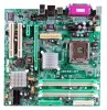
(only for 945G -M 7) IDE1 JRJ45USB 1 Su p er I /O JA UDIO1 J A UD IO2 JAT XPWR 1 PCI-E X 16 94 5G or 9 45P J C DIN 1 COD EC Giga LA N / L AN PCI- EX1_1 PC I1 PCI 2 JS PD IF_OU T1 J SP DIF_IN 1 (o p ti o n a l ) BI OS J DJ 1 (o p ti o n a l ) BAT1 J_C IR 1 (o p ti o n a )l Intel ICH7 SATA4 - Biostar I945G-M7 | Setup Manual - Page 8
945G-M7 / 945P-M7 CHAPTER 2: HARDWARE INSTALLATION 2.1 INSTALLING CENTRAL PROCESSING UNIT (CPU) Special Notice: Remove Pin Cap before installation, and make good preservation for future use. When the CPU is removed, cover the Pin Cap on the empty socket to ensure pin legs won't be damaged. Pin Cap - Biostar I945G-M7 | Setup Manual - Page 9
945G-M7 / 945P-M7 Step 2: Look for the triangular cut edge on socket, and the golden dot on CPU should point forwards this triangular cut edge. The CPU will fit only in the correct orientation. Step 2-1: Step 2-2: Step 3: Hold the CPU down firmly, and then lower the lever to locked position to - Biostar I945G-M7 | Setup Manual - Page 10
945G-M7 / 945P-M7 2.2 FAN HEADERS These fan headers support cooling-fans built in the computer r JCFA N1 4 1 Pin 1 2 3 4 Assignment Ground Power FAN RPM rate sense Smart Fan Control JSFAN1: System Fan He ader Pin 1 2 3 JS FA N1 31 Assignment Ground +12V FAN RPM rate sense Note: The JCFAN1 - Biostar I945G-M7 | Setup Manual - Page 11
DD R2_A1 D DR 2_A2 DD R2_B1 D DR 2_B2 945G-M7 / 945P-M7 2.3 INSTALLING SYSTEM MEMORY 1. Unlock a DIMM slot by pressing the retaining clips outward. Align a DIMM on the slot such that the notch on the DIMM matches the break - Biostar I945G-M7 | Setup Manual - Page 12
945G-M7 / 945P-M7 2.4 CONNECTORS AND SLOTS FDD1: Floppy Disk Connector T he motherboard provides a standard floppy disk connector that supports 360K, 720K, 1.2M, 1.44M and 2.88M floppy disk types. This connector supports the provided floppy drive ribbon cables. 34 33 2 1 IDE1: Hard Disk - Biostar I945G-M7 | Setup Manual - Page 13
945G-M7 / 945P-M7 PCI1~PCI2: Peripheral Component Interconnect Slots This motherboard is equipped with 2 standard PCI slots. PCI stands for Peripheral Component Interconnect, and it is a bus standard for expansion cards. This PCI slot is designated as 32 bits. PCI1 PCI2 PCI-EX16: PCI-Express x16 - Biostar I945G-M7 | Setup Manual - Page 14
945G-M7 / 945P-M7 CHAPTER 3: HEADERS & JUMPERS SETUP 3.1 HOW TO SETUP JUMPERS The illustration shows how to set up jumpers. When the jumper cap is placed on pins, the - Biostar I945G-M7 | Setup Manual - Page 15
945G-M7 / 945P-M7 JATXPWR2: ATX Power Connector By connecting this connector, it will provide +12V to CPU power circuit. 2 1 4 3 Pin Assignment 1 +12V 2 +12V 3 Ground 4 Ground SATA1~SATA4: Serial ATA Connectors The motherboard has a PCI to SATA Controller with 4 channels SATA interf - Biostar I945G-M7 | Setup Manual - Page 16
945G-M7 / 945P-M7 JKBV1: Power Source Header for PS/2 Keyboard and Mouse 3 1 31 Pin 1-2 Close (Default) +5V for PS/2 keyboard and mouse. 31 Pin 2-3 close PS/2 keyboard and mouse are powered by +5V standby voltage. Note: In order to support this func tion "Power-on s ystem via keyboar d and - Biostar I945G-M7 | Setup Manual - Page 17
945G-M7 / 945P-M7 JPANEL1: Front Panel Header This 24-pin connector includes Power-on, n Sleep button N/A Power LED Power-on button IrDA Connector JCI1: Chassis Open Header This connector allows system to monitor PC case open status. If the signal has been triggered, it will record to the CMOS - Biostar I945G-M7 | Setup Manual - Page 18
945G-M7 / 945P-M7 JCDIN1: CD-RO M Audio-in Connector This connector allows user to connect the audio source f rom the variety dev it allows user to restore the BIOS saf e setting and the CMOS data, please carefully f ollow the procedures to avoid damaging the motherboard. 31 Pin 1-2 Close: Normal - Biostar I945G-M7 | Setup Manual - Page 19
945G-M7 / 945P-M7 JSPDIF_OUT1: Digital Audio-out Connector This connector allows user to connect the PCI bracket SPDIF output header. Pin Assignment 1 +5V 2 SPDIF_OUT 3 Ground 3 1 JSPDIF_IN1 (optional): Digital Audio-in Connector This connector allows user to connect the PCI bracket SPDIF - Biostar I945G-M7 | Setup Manual - Page 20
945G-M7 / 945P-M7 CHAPTER 4: USEFUL HELP 4.1 AWARD BIOS BEEP CODE Beep Sound One long beep followed by two short beeps Meaning Video card not found or v ideo card memory bad High-low siren sound CPU overheated System will shut down automatically One Short beep when system boot-up No error - Biostar I945G-M7 | Setup Manual - Page 21
945G-M7 / 945P-M7 B. CPU Overheated If the system shutdown automatically after power on system for seconds, that means the CPU protection function has been activated. When the CPU is over heated, the motherboard will shutdown automatically to avoid a damage of the CPU, and the system may not power - Biostar I945G-M7 | Setup Manual - Page 22
945G-M7 / 945P-M7 4.3 TROUBLESHOOTING Probable Solution 1. No power to the system at all 1. Make sure power cable is Power light don't illuminate, f an securely plugged in. inside power supply does not turn 2. Replace cable. on. 3. Contact technical support. 2. Indicator light on key board - Biostar I945G-M7 | Setup Manual - Page 23
a speed that is either the original system speed or a suitable one. 5.2 SYSTEM REQUIREMENT OS Support: Windows 98 SE, Windows Me, Windows 2000, Windows XP DirectX: DirectX 8.1 or above. (The Windows XP operating system includes DirectX 8.1. If you use Windows XP, you do not need to install DirectX - Biostar I945G-M7 | Setup Manual - Page 24
945G-M7 / 945P-M7 5.3 INSTALLATION 1. Execute the setup execution file, and then the following dialog will pop up. Please click "Next" button . Usage : The following figures are just only for reference, the screen printed in this user manual will change according to your motherboard on hand. 22 - Biostar I945G-M7 | Setup Manual - Page 25
945G-M7 / 945P-M7 5.4 [WARPSPEEDER™] INCLUDES 1 TRAY ICON AND 5 PANELS 1. Tray Icon: Whenever the Tray Icon utility is launched, it will display a little tray icon on the right side of Windows Taskbar. This utility is responsible for conveniently invoking [WarpSpeeder™] Utility. You can use the - Biostar I945G-M7 | Setup Manual - Page 26
945G-M7 / 945P-M7 2. Main Panel If you click the tray icon, [WarpSpeeder™] utility will be invoked. Please refer to the following figure; the utility's first window you will see is Main Panel. Main Panel contains fe ature s as follows: a. Display the CPU Speed, CPU external clock, Memory clock, AGP - Biostar I945G-M7 | Setup Manual - Page 27
945G-M7 / 945P-M7 3. Vol tage Panel Click the Voltage button in Main Panel, the button will be highlighted and the Voltage Panel will slide out to up as the following figure. In this panel, you can decide to increase CPU core voltage and Memory voltage or not. The default setting is "No". If you - Biostar I945G-M7 | Setup Manual - Page 28
945G-M7 / 945P-M7 4. Overclock Panel button": provide user the ability to do real-time overclock adjustment. Warning: Manually overclock is potentially dangerous, especially when the ov erclocking percentage is over 110 . Let user select a restoring way if system need to do a fail-safe reboot. 26 - Biostar I945G-M7 | Setup Manual - Page 29
945G-M7 / 945P-M7 c. "Auto-overclock button": User can click this button and [WarpSpeeder™] will set the best and stable performance and frequency automatically. [WarpSpeeder™] utility will execute a series of testing until system fail. Then system will do fail-safe reboot by using Watchdog function - Biostar I945G-M7 | Setup Manual - Page 30
945G-M7 / 945P-M7 6. About Panel Click the "about" button in Main Panel, the button will be highlighted and the About Panel will slide out to up as the following figure. In this panel, you can get model name and detail information in hints of all the chipset that are related to overclocking. You can - Biostar I945G-M7 | Setup Manual - Page 31
945G-M7 / 945P-M7 Note : Because the overclock, overvoltage, and hardware monitor features are controlled by several separate chipset, [WarpSpeeder™] divide these features to separate panels. If one chipset is not on board, the correlative button in Main panel will be disabled, but will not - Biostar I945G-M7 | Setup Manual - Page 32
945G-M7 & 945P-M7 BIOS SETUP BIOS Setup 1 1 Main Menu...3 2 Standard CMOS Features 6 3 Advanced BIOS Features 9 4 Advanced Chipset Features 16 5 Integrated Peripherals 20 6 Power Management Setup 26 7 PnP/PCI Configurations 31 8 PC Health Status 33 9 Frequency/ Voltage Control 35 i - Biostar I945G-M7 | Setup Manual - Page 33
password protection as well as special support for detailed fine-tuning of the chipset controlling the entire system. The rest of this manual is intended to guide you through the process of configuring your system using Setup. Plug and Play Support These AWARD BIOS supports the Plug and Play Version - Biostar I945G-M7 | Setup Manual - Page 34
945G-M7 & 945P-M7 BIOS SETUP PCI Bus Support This AWARD BIOS also supports Version 2.1 of the Intel PCI (Peripheral Component Interconnect) local bus specification. DRAM Support DDR2 SDRAM (Double Data Rate Two Synchronous DRAM) are supported. Supported CPUs This AWARD BIOS supports the Intel CPU. - Biostar I945G-M7 | Setup Manual - Page 35
945G-M7 & 945P-M7 BIOS SETUP 1 Main Menu Once you enter Award BIOS™ CMOS Setup Utility, the Main Menu will WARNING !! The information about BIOS defaults on manual (Figure 1,2,3,4,5,6,7,8,9) is just for reference, please refer to the BIOS installed on board, for update information. Figure 1. Main - Biostar I945G-M7 | Setup Manual - Page 36
945G-M7 & 945P-M7 BIOS SETUP Integrated Peripherals This submenu allows you to configure certain IDE voltage and clock may cause the CPU or M/B damage!) Load Optimized Defaults This selection allows you to reload the BIOS when the system is having problems particularly with the boot sequence. These - Biostar I945G-M7 | Setup Manual - Page 37
945G-M7 & 945P-M7 BIOS SETUP Set User Password If the Supervisor Password is not set, then the User Password will function in the all changes made during the current session and exit setup. message will be displayed before proceeding. confirmation Upgrade BIOS This submenu allows you to upgrade - Biostar I945G-M7 | Setup Manual - Page 38
945G-M7 & 945P-M7 BIOS SETUP 2 Standard CMOS Features The items in Standard CMOS Setup Menu are divided into 10 categories. Each category includes no, one or more than one - Biostar I945G-M7 | Setup Manual - Page 39
945G-M7 & 945P-M7 BIOS SETUP Main Menu Selections This table shows the 3.5 in None EGA/VGA CGA 40 CGA 80 MONO Description Set the system date. Note that the 'Day' automatically changes when you set the date. Set the system internal clock. Press to enter the sub menu of detailed options - Biostar I945G-M7 | Setup Manual - Page 40
945G-M7 & 945P-M7 BIOS SETUP Item Halt On Base Memory Extended Memory Total Memory Options All Errors No Errors All, but Keyboard All, but Diskette All, but Disk/ Key N/A N/A N/A Description Select the situation in which you want the BIOS to stop the POST process and notify you. Displays the - Biostar I945G-M7 | Setup Manual - Page 41
945G-M7 & 945P-M7 BIOS SETUP 3 Advanced BIOS Features Figure 3. Advanced BIOS Setup CPU FEATURE Delay Prior to Thermal Set this item to enable the CPU Thermal function to engage after the specified time. The Choices: 4, 8, 16 (default), 32. Thermal Management This option allows you to choose the - Biostar I945G-M7 | Setup Manual - Page 42
945G-M7 & 945P-M7 BIOS SETUP TM2 Bus Ratio This option represents the frequency. ( default), 0.8375-1.6000. Limit CPUID MaxVal Set limit CPUID MaxVal to 3, it should be "Disabled" for Win XP. The Choices: Disabled (default), Enabled. C1E Function This item allows you to choose the C1E function. The - Biostar I945G-M7 | Setup Manual - Page 43
945G-M7 & 945P-M7 BIOS SETUP Cache Setup CPU L3 Cache Depending on the CPU/chipset in use, you may be able to increase memory access time with this option. Enabled (default) Enable cache. Disabled Disable cache. 11 - Biostar I945G-M7 | Setup Manual - Page 44
945G-M7 & 945P-M7 BIOS SETUP Boot Seq & Floppy Setup This item allows you to setup Boot Seq & Floppy. Hard Disk Boot Priority These BIOS attempt to arrange the Hard Disk boot sequence automatically. This will depend on which Hard Disk is installed. The Choices: Pri. Master, Pri.Slave, Sec. - Biostar I945G-M7 | Setup Manual - Page 45
945G-M7 & 945P-M7 BIOS SETUP First/Second/Third/Boot Other Device These BIOS attempt to load the operating system from the device in the sequence selected in these items. The Choices: Floppy, LS120, HDD-0, SCSI, CDROM, ZIP100, LAN, Disabled. Swap Floppy Drive For systems with two floppy drives, - Biostar I945G-M7 | Setup Manual - Page 46
. The Choices: Enabled (default), Disabled. MPS Version Control For OS The BIOS supports version 1.1 and 1.4 of the Intel multiprocessor specification. Select version supported by the operation system running on this computer. The Choices: 1.4 (default), 1.1. OS Select For DRAM > 64MB A choice - Biostar I945G-M7 | Setup Manual - Page 47
945G-M7 & 945P-M7 BIOS SETUP Small Logo (EPA) Show This item allows you to select whether the "Small Logo" shows. Enabled (default) "Small Logo" shows when system boot up. Disabled No "Small Logo" shows when system boots up. Summary Screen Show This item allows you to enable/disable the - Biostar I945G-M7 | Setup Manual - Page 48
945G-M7 & 945P-M7 BIOS SETUP 4 Advanced Chipset Features This submenu allows you to configure the specific features of the chipset installed on your system. This chipset manage bus speeds and access to system memory resources, such as DRAM. It also coordinates communications with the PCI bus. The - Biostar I945G-M7 | Setup Manual - Page 49
945G-M7 & 945P-M7 BIOS SETUP DRAM RAS# Precharge If an insufficient number of cycles clocks to activate the precharge delay. The Choices: Auto (default), 4/5/6/7/8/9/10/11/12/13/14/15. System Memory Frequency This item allows you to select the Memory Frequency. The Choices: Auto (default), 400MHz, - Biostar I945G-M7 | Setup Manual - Page 50
945G-M7 & 945P-M7 BIOS SETUP PCI Express Root Port Func PCI Express Port This item allows you to select the PCI Express Port. The Choices: Auto (default), Enabled, Disabled. PCI-E Compliancy Mode This item allows you to select the PCI-E Compliancy Mode. The Choices: v1.0a (default), v1.0. VGA - Biostar I945G-M7 | Setup Manual - Page 51
945G-M7 & 945P-M7 BIOS SETUP DVMT Memory Size DVMT stands for „Dynamic Video Memory Technology". This is an enhancemnet of the unified memory architecture (UMA) concept. Where the optimum amount of memory is allocated for balanced graphics and system performance. DVMT dynamically reponds to system - Biostar I945G-M7 | Setup Manual - Page 52
945G-M7 & 945P-M7 BIOS SETUP 5 Integrated Peripherals Figure 5. Integrated Peripherals OnChip IDE Device If you highlight the literal "Press Enter" next to the "OnChip IDE Device" label and then press the enter key, it will take you a submenu with the following options: 20 - Biostar I945G-M7 | Setup Manual - Page 53
by the IDE hard drives in your system. As well, your operating environment requires a DMA driver (Windows 95 OSR2 or a third party IDE bus master driver). If your hard drive and your system software both support Ultra DMA/100, select Auto to enable BIOS support. The Choices: Auto (default), Disabled - Biostar I945G-M7 | Setup Manual - Page 54
945G-M7 & 945P-M7 BIOS SETUP On-Chip Serial ATA This item allows you to choose: Disabled: disabled SATA Controller Combined Mode: PATA and SATA are combined max of 2 IDE drivers in each channel. Enhanced Mode: enabled both SATA and PATA max of 6 IDE drivers are supported. SATA Only: SATA is - Biostar I945G-M7 | Setup Manual - Page 55
945G-M7 & 945P-M7 BIOS SETUP Onboard Device If you highlight the literal "Press Enter" next to the "Onboard Device" label and then press the enter key, it will take you a submenu with the following options: USB Controller Select Enabled if your system contains a Universal Serial Bus (USB) - Biostar I945G-M7 | Setup Manual - Page 56
945G-M7 & 945P-M7 BIOS SETUP Onboard RAID The Choices: Enabled (default), Disabled. Onboard RAID BIOS The Choices: Enabled (default), Disabled. Onboard 1394 The Choices: Enabled (default), Disabled. Onboard LAN This item allows you to enable or disable the Onboard LAN. The Choices: Enabled - Biostar I945G-M7 | Setup Manual - Page 57
945G-M7 & 945P-M7 BIOS SETUP Onboard Serial Port 1 Select an address and corresponding interrupt the port. The Choices: 3 (default), 1. PWRON After PWR-Fail This setting specifies whether your system will reboot after a power fail or interrupts occurs. Off Leaves the computer in the power off - Biostar I945G-M7 | Setup Manual - Page 58
945G-M7 & 945P-M7 BIOS SETUP 6 Power Management Setup The Power Management Setup Menu allows you to configure your system to utilize energy conservation and power up/power down features. Figure 6. Power Management Setup ACPI & Wake Up Events ACPI Function This item displays the status - Biostar I945G-M7 | Setup Manual - Page 59
Enabled will make BIOS run VGA BIOS to initialize the VGA card when system wakes up from S3 state. The system time is shortened if you disable the function, but system will need AGP driver to initialize the card. So, if the AGP driver of the VGA card does not support the initialization feature - Biostar I945G-M7 | Setup Manual - Page 60
945G-M7 & 945P-M7 BIOS SETUP KB POWER ON Password Input password and press Enter to set the Keyboard power on password. Hot Key Power ON Input password and press - Biostar I945G-M7 | Setup Manual - Page 61
945G-M7 & 945P-M7 BIOS SETUP Power Management This category allows you to select the type (or Suspend Mode = 1 hr. HDD Power Down = 15 min Max. Power Saving Maximum power management only available for sl CPU's. Suspend Mode = 1 min. HDD Power Down = 1 min. User Define (default) Allows you to set each - Biostar I945G-M7 | Setup Manual - Page 62
945G-M7 & 945P-M7 BIOS SETUP Suspend Mode The item allows you to select the suspend type under ACPI operating system. The Choices: Disabled (default), 1 Min, 2 Min, 4 Min, 6 Min, 8 Min, 10 Min, 20 Min, 30 Min, 40 Min, 1 Hour. This selection will cause the system set time of system inactivity. All - Biostar I945G-M7 | Setup Manual - Page 63
945G-M7 & 945P-M7 BIOS SETUP 7 PnP/PCI Configurations This section describes configuring the PCI bus system. PCI, or Personal Computer Interconnect, is a system which allows I/O devices to operate at speeds nearing the speed of the CPU itself uses when communicating with its own special components. - Biostar I945G-M7 | Setup Manual - Page 64
945G-M7 & 945P-M7 BIOS SETUP IRQ Resources This submenu will allow you to assign each system interrupt a type, depending on the type of device using the interrupt. When you press the "Press Enter" tag, you will be directed to a submenu that will allow you to configure the system graphic controllers - Biostar I945G-M7 | Setup Manual - Page 65
Temperature This item allows you to set up the CPU shutdown Temperature. This item only effective under Windows 98 ACPI mode The Choices: 60℃/ 140℃, 65℃/ 149℃, 70℃/ 158℃, Disabled (default). Show H/W Monitor in POST If your computer contains a monitoring system, it will show PC health status during - Biostar I945G-M7 | Setup Manual - Page 66
945G-M7 & 945P-M7 BIOS SETUP Current CPU FAN Speed This field displays the current speed of CPU fan. Current SYS FAN Speed This field displays the current speed SYSTEM fan. 34 - Biostar I945G-M7 | Setup Manual - Page 67
945G-M7 & 945P-M7 BIOS SETUP 9 Frequency/ Voltage Control Figure 9. Frequency/ Voltage Control CPU Clock Ratio This item allows you to select the CPU Ratio. Min = 8 Max = 50 Key in a DEC number. The Choices: 8X (default). CPU Voltage Regulator This item allows you to select CPU Voltage Regulator The - Biostar I945G-M7 | Setup Manual - Page 68
945G-M7 & 945P-M7 BIOS SETUP Method 1: Clear the COMS data by setting the JCOMS1 ((2-3) closed showed. This action will boot-up the system according to FSB of the processor It's strongly recommended to set CPU Vcore and clock in default setting. If the CPU Vcore and clock are not in default setting
-
 1
1 -
 2
2 -
 3
3 -
 4
4 -
 5
5 -
 6
6 -
 7
7 -
8
-
9
-
10
-
11
-
12
-
13
-
14
-
15
-
16
-
17
-
18
-
19
-
20
-
21
-
22
-
23
-
24
-
25
-
26
-
27
-
28
-
29
-
30
-
31
-
32
-
33
-
34
-
35
-
36
-
37
-
38
-
39
-
40
-
41
-
42
-
43
-
44
-
45
-
46
-
47
-
48
-
49
-
50
-
51
-
52
-
53
-
54
-
55
-
56
-
57
-
58
-
59
-
60
-
61
-
62
-
63
-
64
-
65
-
66
-
67
-
68
 |
 |

945G-M7 / 945P-M7
i
FCC Information and Copyright
This equipment has been tested and found to comply with the limits of a Class
B digital device, pursuant to Part 15 of the FCC Rules. These limits are designed
to provide reasonable protection against harmful interference in a residential
installation. This equipment generates, uses and can radiate radio frequency
energy and, if not installed and used in accordance with the instructions, may
cause harmful interference to radio communications. There is no guarantee
that interference will not occur in a particular installation.
The vendor makes no representations or warranties with respect to the
contents here and specially disclaims any implied warranties of merchantability
or fitness for any purpose. Further the vendor reserves the right to revise this
publication and to make changes to the contents here without obligation to
notify any party beforehand.
Duplication of this publication, in part or in whole, is not allowed without first
obtaining the vendor’s approval in writing.
The content of this user’s manual is subject to be changed without notice and
we will not be responsible for any mistakes found in this user’s manual. All the
brand and product names are trademarks of their respective companies.