Biostar K8M80-M7A K8M800-M7A user's manual - Page 14
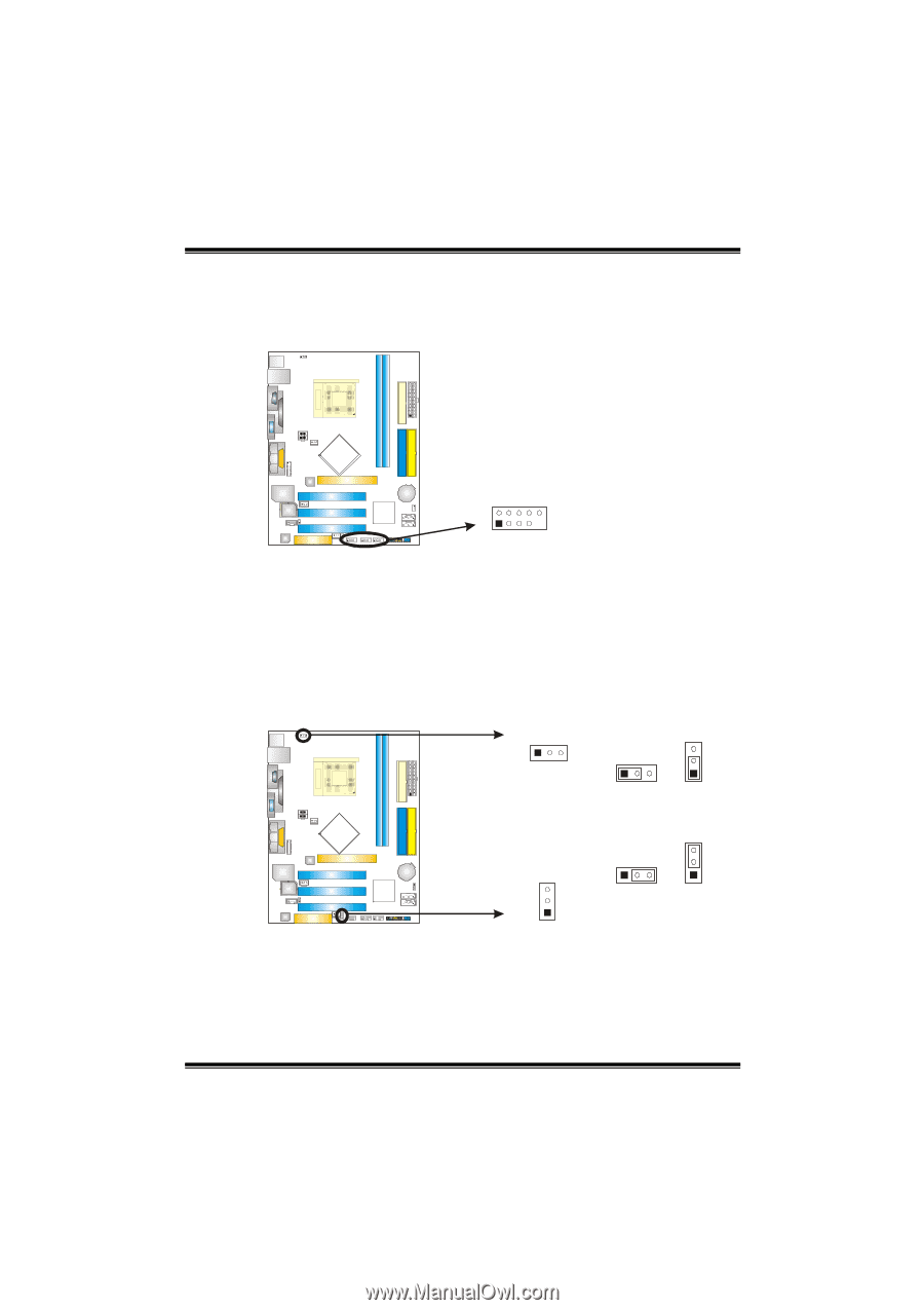
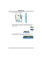
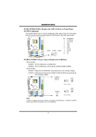
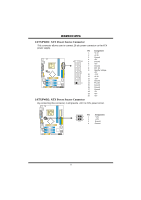
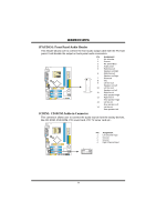
JUSB1/JUSB2/JUSB3: Headers for USB 2.0 Ports at Front Panel, JUSB3 is optional, JUSBV1/JUSBV2: Power
 |
View all Biostar K8M80-M7A manuals
Add to My Manuals
Save this manual to your list of manuals |
Page 14 highlights
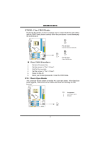
K8M800-M7A JUSB1/JUSB2/JUSB3: Headers for USB 2.0 Ports at Front Panel (JUSB3 is optional) This header allows user to connect additional USB cable on the PC front panel, and also can be connected with internal USB devices, like USB card reader. Pin Assignment 1 +5V (fused) 2 +5V (fused) 3 USB- 4 USB- 5 USB+ 6 USB+ 7 Ground JUSB1 JUSB2 JUSB3 8 Ground 2 10 9 Key 10 NC 1 9 JUSBV1/JUSBV2: Power Source Headers for USB Ports Pin 1-2 Close: JUSBV1: +5V for USB ports at JUSBLAN1. JUSBV2: +5V for USB ports at front panel (JUSB1/JUSB2/JUSB3). Pin 2-3 Close: JUSBV1: USB ports at JUSBLAN1 are powered by +5V standby voltage. JUSBV2: USB ports at front panel (JUSB1/JUSB2/JUSB3) are powered by +5V standby voltage. JUSBV1 13 3 1 3 1 Pin 1-2 close JUSBV2 3 1 3 1 3 1 Pin 2-3 close Note: In order to support this function "Power-On system via USB device," "JUSBV1/ JUSBV2" jumper cap should be placed on Pin 2-3 individually. 12
-
 1
1 -
2
-
3
-
4
-
5
-
6
-
7
-
8
-
 9
9 -
 10
10 -
 11
11 -
 12
12 -
 13
13 -
 14
14 -
 15
15 -
 16
16 -
 17
17 -
 18
18 -
 19
19 -
20
-
21
-
22
-
23
-
24
-
25
-
26
-
27
-
28
-
29
-
30
 |
 |