Biostar K8M800 Setup Manual
Biostar K8M800 Manual
 |
View all Biostar K8M800 manuals
Add to My Manuals
Save this manual to your list of manuals |
Biostar K8M800 manual content summary:
- Biostar K8M800 | Setup Manual - Page 1
K8M800-M7A FCC Information and Copyright This equipment has been tes ted and found to comply with the limits of a Class B digital devic e, purs uant to Part 15 of the FCC Rules .T hese limits are designed to provide reasonable protec tion against harmful interference in a residential installation. T - Biostar K8M800 | Setup Manual - Page 2
Central Processing Unit (CPU 5 2.2 FAN Headers 6 2.3 Installing System Memory 7 2.4 Connectors and Slots 8 Chapter 3: Headers & Jumpers Setup 11 3.1 How to Setup Jumpers 11 3.2 Detail Settings 11 Chapter 4: Useful Help 17 4.1 Award BIOS Beep Code 17 4.2 Extra Information - Biostar K8M800 | Setup Manual - Page 3
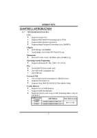
INTRODUCTION 1.1 MOTHERBOARD FEATURES C PU Supports Socket 754. Supports AMD Athlon 64 processor up to 3700+. Supports AMD Sempron processo r. Supports HyperTransport Technology up to 1600MT/s. Chi pset North Bridge: VIA K8M800. South Bridge: VIA VT8237R/VT8237R PLUS. Dimensions Micro ATX Form - Biostar K8M800 | Setup Manual - Page 4
K8M800-M7A Supe r I/O Chip: ITE IT8705AF. Low Pin Count Interface. Provides the most commonly used legacy Super I/O fu n ctio n ali ty. Environment Control initiatives, H/W Monitor Fan Speed Controller ITE's "Smart Guardian" function Onboard AC'97 Sound Code c Chip: REALTEK ALC655. Support 6 - Biostar K8M800 | Setup Manual - Page 5
K8M800-M7A Inte rnal On-board I/O Conne ctors and Heade rs 1 front panel header supports front panel facilities. 1 CD-in connector supports 1 CD-ROM audio-in device. 1 front audio header supports front panel audio function. 1 S/PDIF-Out connector supports digital audio-out function. 1 chassi s open - Biostar K8M800 | Setup Manual - Page 6
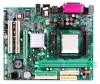
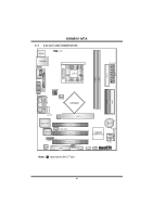
K8M800-M7A 1.3 LAYOUT AND COMPONENTS JKBMS1 JUSBV1 JUSBLAN1 CPU1 JAT XPWR1 DIMM1 DIMM2 FD D1 S ocket 754 JCOM1 JPRNT1 JV GA1 ID E1 ID E2 JAUD_GAM E JGame Port JATXPWR2 JCFAN1 K8 M800 JAUDIO2 LAN PHY AGP1 Super I/O BIO S PCI1 JSPDIF_OUT1 PCI2 BAT1 VT8237R/ VT8237 R PLUS JCM - Biostar K8M800 | Setup Manual - Page 7
K8M800-M7A CHAPTER 2: HARDWARE INSTALLATION 2.1 INSTALLING CENTRAL PROCESSING UNIT (CPU) Step 1: Pull the lever toward direction A from the socket and then raise the lever up to a 90-degree angle. 90 A Step 2: Look for the white triangle on socket, and the gold triangle on CPU should point forwards - Biostar K8M800 | Setup Manual - Page 8
K8M800-M7A 2.2 FAN HEADERS These fan headers support cooling-fans built in the computer. The fan cable and connector may be different according to the fan manufacturer. Connect the fan cable to the connector while matching the black wire to pin#1. JC FAN1: C PU Fan Heade r JSFAN1: System Fan He ader - Biostar K8M800 | Setup Manual - Page 9
DIMM1 DIMM2 K8M800-M7A 2.3 INSTALLING SYSTEM MEMORY 1. Unlock a DIMM slot by pressing the retaining clips outward. Align a DIMM on the slot such that the notch on the DIMM matches the break on - Biostar K8M800 | Setup Manual - Page 10
K8M800-M7A 2.4 CONNECTORS AND SLOTS FDD1: Floppy Disk Connector T he motherboard provides a standard floppy disk connector that supports 360K, 720K, 1.2M, 1.44M and 2.88M floppy disk types. This connector supports the provided floppy drive ribbon cables. 34 33 2 1 IDE1/IDE2: Hard Disk - Biostar K8M800 | Setup Manual - Page 11
K8M800-M7A PCI1~PCI3: Peripheral Component Interconnect Slots This motherboard is equipped with 3 : Accel erated Graphi cs Port Sl ot Your monitor will attach directly to that video card. This motherboard supports video cards for PCI slots, but it is also equipped with an Accelerated Graphics Port - Biostar K8M800 | Setup Manual - Page 12
K8M800-M7A CNR1: Communication Network Riser Slot The CNR specification is an open Industry Standard Architecture, and it defines a hardware scalable riser card interface, which supports modem only. 10 - Biostar K8M800 | Setup Manual - Page 13
K8M800-M7A CHAPTER 3: HEADERS & JUMPERS SETUP 3.1 HOW TO SETUP JUMPERS The illustration shows how to set up jumpers. When the jumper cap is placed on pins, the - Biostar K8M800 | Setup Manual - Page 14
K8M800-M7A JUSB1/JUSB2/JUSB3: He ade rs for USB 2.0 Ports at Front Panel (JUSB3 is optional) This header allows user to connect additional USB cable on - Biostar K8M800 | Setup Manual - Page 15
K8M800-M7A JATXPWR1: ATX Powe r Source C onne ctor This connector allows user to connect 20-pin power connector on the : ATX Powe r Source C onne ctor By connecting this connector, it will provide +12V to CPU power circuit. Pin Assignment 4 3 1 +12V 2 1 2 +12V 3 Ground 4 Ground 13 - Biostar K8M800 | Setup Manual - Page 16
K8M800-M7A JFAUDIO1: Front Panel Audio Heade r This header allows user to connect the front audio output cable with the PC f ront panel. It will disable the output on back panel audio connectors. Pin Assignment 1 Mic in/center 2 Ground 3 Mic power/Bass 4 Audio power 5 Right line out/ - Biostar K8M800 | Setup Manual - Page 17
K8M800-M7A JCMO S1: Cle ar CMOS Heade r By placing the jumper on pin2-3, it allows user to restore the BIOS saf e setting and the CMOS data, please carefully f ollow the procedures to avoid damaging the motherboard Chassis O pen Heade r This connector allows system to monitor PC case open status. If - Biostar K8M800 | Setup Manual - Page 18
K8M800-M7A JSATA1~JSATA2: Se rial ATA Connectors The motherboard has a PCI to SATA Controller with 2 channels SATA interf ace, it satisfies the SATA 1.0 spec and with transfer rate of 1.5GB/s. 741 Pin Assignment 1 Ground 2 TX+ 3 TX4 Ground 5 RX6 RX+ 7 Ground JS ATA1 JSPDIF_O UT1: Digital Audio- - Biostar K8M800 | Setup Manual - Page 19
K8M800-M7A CHAPTER 4: USEFUL HELP 4.1 AWARD BIOS BEEP CODE Beep Sound One long beep followed by two short beeps Meaning Video card not found or v ideo card memory bad High-low siren sound CPU overheated System will shut down automatically One Short beep when system boot-up No error found - Biostar K8M800 | Setup Manual - Page 20
K8M800-M7A B. CPU Overheated If the system shutdown automatically after power on system for seconds, that means the CPU protection function has been activated. When the CPU is over heated, the motherboard will shutdown automatically to avoid a damage of the CPU, and the system may not power on again - Biostar K8M800 | Setup Manual - Page 21
K8M800-M7A 4.3 TROUBLESHOOTING Probable Solution 1. No power to the system at all 1. Make sure power cable is Power light don't illuminate, f an securely plugged in. inside power supply does not turn 2. Replace cable. on. 3. Contact technical support. 2. Indicator light on key board does - Biostar K8M800 | Setup Manual - Page 22
that is either the original system speed or a suitable one. 5.2 SYSTEM REQUIREMENT OS Support: Windows 98 SE, Windows Me, Windows 2000, Windows XP DirectX: DirectX 8.1 or above. (The Windows XP operating system includes DirectX 8.1. If you use Windows XP, you do not need to install DirectX 8.1.) 20 - Biostar K8M800 | Setup Manual - Page 23
K8M800-M7A 5.3 INSTALLATION 1. Execute the setup execution file, and then the following dialog will pop up. Please click "Next" button and follow . Usage : The following figures are just only for reference, the screen printed in this user manual will change according to your motherboard on hand. 21 - Biostar K8M800 | Setup Manual - Page 24
K8M800-M7A 5.4 [WARPSPEEDER™] INCLUDES 1 TRAY ICON AND 5 PANELS 1. Tray Icon: Whenever the Tray Icon utility is launched, it will display a little tray icon on the right side of Windows Taskbar. This utility is responsible for conveniently invoking [WarpSpeeder™] Utility. You can use the mouse by - Biostar K8M800 | Setup Manual - Page 25
K8M800-M7A 2. Main Panel If you click the tray icon, [WarpSpeeder™] utility will be invoked. Please refer to the following figure; the utility's first window you will see is Main Panel. Main Panel contains fe ature s as follows: a. Display the CPU Speed, CPU external clock, Memory clock, AGP clock, - Biostar K8M800 | Setup Manual - Page 26
K8M800-M7A 3. Vol tage Panel Click the Voltage button in Main Panel, the button will be highlighted and the Voltage Panel will slide out to up as the following figure. In this panel, you can decide to increase CPU core voltage and Memory voltage or not. The default setting is "No". If you want to - Biostar K8M800 | Setup Manual - Page 27
K8M800-M7A 4. Overclock Panel button": provide user the ability to do real-time overclock adjustment. Warning: Manually overclock is potentially dangerous, especially when the ov erclocking percentage is over 110 dialog. Let user select a restoring way if system need to do a fail-safe reboot. 25 - Biostar K8M800 | Setup Manual - Page 28
K8M800-M7A c. "Auto-overclock button": User can click this button and [WarpSpeeder™] will set the best and stable performance and frequency automatically. [WarpSpeeder™] utility will execute a series of testing until system fail. Then system will do fail-safe reboot by using Watchdog function. After - Biostar K8M800 | Setup Manual - Page 29
K8M800-M7A 6. About Panel Click the "about" button in Main Panel, the button will be highlighted and the About Panel will slide out to up as the following figure. In this panel, you can get model name and detail information in hints of all the chipset that are related to overclocking. You can also - Biostar K8M800 | Setup Manual - Page 30
K8M800-M7A Note : Because the overclock, overvoltage, and hardware monitor features are controlled by several separate chipset, [WarpSpeeder™] divide these features to separate panels. If one chipset is not on board, the correlative button in Main panel will be disabled, but will not interfere other - Biostar K8M800 | Setup Manual - Page 31
K8M800-M7A BIOS Setup BIOS Setup...1 1 Main Menu...3 2 Standard CMOS Features...6 4 Advanced Chipset Features...15 5 Integrated P eripherals...21 6 P ower Management Setup...28 7 P nP /P CI Configurations...34 8 P C Health Status...37 9 Frequency/ Voltage Control...39 i - Biostar K8M800 | Setup Manual - Page 32
-backed RAM so that it retains the Setup information when the power is turned off. The Award BIOS™ installed in your computer system's ROM (Read Only Memory) is a custom version of an industry standard BIOS. This means that it supports AMD processor input/output system. The BIOS provides critical - Biostar K8M800 | Setup Manual - Page 33
K8M800-M7A BIOS Setup PCI Bus Support This AWARD BIOS also supports Version 2.1 of the Intel P CI (P eripheral Component Interconnect) local bus specification. DRAM Support DDR SDRAM (Double Data Rate Synchronous DRAM) are supported. Supported CPUs This AWARD BIOS supports the AMD CP U. Using - Biostar K8M800 | Setup Manual - Page 34
K8M800-M7A BIOS Setup 1 Main Menu Once you enter Award BIOS™ CMOS Setup Utility, the Main Menu will appear WARNING !! The information about BIOS defaults on manual (Figure 1,2,3,4,5,6,7,8,9) is just for reference, please refer to the BIOS installed on board, for update information. „ Figure 1: Main - Biostar K8M800 | Setup Manual - Page 35
K8M800-M7A BIOS Setup Integrated Peripherals This submenu allows you to configure certain IDE hard voltage and clock may cause the CPU or M/B damage! ) Load Optimized Defaults This selection allows you to reload the BIOS when the system is having problems particularly with the boot sequence. These - Biostar K8M800 | Setup Manual - Page 36
K8M800-M7A BIOS Setup Set User Password If the Supervisor P assword is not set, then the will not be able to change them. Save & Exit Setup Save all configuration changes to CMOS(memory) and exit setup. Confirmation message will be displayed before proceeding. Exit Without Saving Abandon all changes - Biostar K8M800 | Setup Manual - Page 37
K8M800-M7A BIOS Setup 2 Standard CMOS Features The items in Standard CMOS Setup Menu are divided into 10 categories. Each category includes no, one or more than one - Biostar K8M800 | Setup Manual - Page 38
K8M800-M7A BIOS Setup Main Menu Selections This table shows the selections that you can make on the Main Menu. Item Options Description Date mm : dd : yy Set the system date. Note that the 'Day ' automatically changes when you set the date. Time hh : mm : ss Set the system internal clock. - Biostar K8M800 | Setup Manual - Page 39
K8M800-M7A BIOS Setup Item Halt On Base Memory Extended Memory Total Memory Options All Errors No Errors All, but Key board All, but Diskette All, but Disk/ Key N/A N/A N/A Description Select the situation in which y ou want the BIOS to stop the POST process and notify y ou. Displays the amount - Biostar K8M800 | Setup Manual - Page 40
K8M800-M7A BIOS Setup 3 Advanced BIOS Features „ Figure 3: Advanced BIOS Setup 9 - Biostar K8M800 | Setup Manual - Page 41
K8M800-M7A BIOS Setup Boot Seq & Floppy Setup This item allows you to setup boot seq & Floppy. „ Figure 3.1: Boot Seq & Floppy Setup Hard Disk Boot Priority These BIOS attempt to arrange the Hard Disk boot sequence automatically. This will depend on which Hard Disk is installed. „ Figure 3.1.1: Hard - Biostar K8M800 | Setup Manual - Page 42
K8M800-M7A BIOS Setup First/ Second/ Third/ Boot Other Device These BIOS attempt to load the operating system from the devices in the sequence selected in these items. The Choices: Floppy (default), LS120, Hard Disk, SCSI, CDROM, ZIP 100, LAN, Disabled. Swap Floppy Drive For systems with two floppy - Biostar K8M800 | Setup Manual - Page 43
K8M800-M7A BIOS Setup Cache Setup „ Figure 3.3: Cache Setup CPU Internal Cache Depending on the CPU/chipset in use, you may be able to increase memory access time with this option. Enabled (default) Enable cache. Disabled Disable cache. External Cache This option enables or disables " Level - Biostar K8M800 | Setup Manual - Page 44
K8M800-M7A BIOS Setup Virus Warning This option allows you to choose the VIRUS Warning feature that is used to protect the IDE Hard Disk boot sector. If this function is enabled and an attempt is made to write to the boot sector, BIOS will display a warning message on the screen and sound an - Biostar K8M800 | Setup Manual - Page 45
K8M800-M7A BIOS Setup APIC Mode Selecting Enabled enables AP IC mode reporting from the BIOS to the operating system. The Choices: Enabled (default), Disabled MPS Version Control For OS The BIOS supports version 1.1 and 1.4 of the Intel multiprocessor specification. Select version supported by the - Biostar K8M800 | Setup Manual - Page 46
K8M800-M7A BIOS Setup 4 Advanced Chipset Features This submenu allows you to configure the specific features of the chipset installed on your system. This chipset manage bus speeds and access to system me mory resources, such as DRAM. It also coordinates communications with the P CI bus. The default - Biostar K8M800 | Setup Manual - Page 47
K8M800-M7A BIOS aperture is a portion of the P CI memory address range dedicated for graphics memory address space. Host cycles that hit the Control By choosing " Auto" the system BIOS will the AGP output Buffer Drive strength P Ctrl by AGP Card. By choosing " Manual", it allows user to set AGP - Biostar K8M800 | Setup Manual - Page 48
K8M800-M7A BIOS Setup AG P Driving Value While AGP driving control item set to " Manual", it allows user to set AGP driving. Enabled. DBI Output for AGP Trans The Choices: Disabled (default), Auto. VG A Share Memory Size This item allows you to select the VGA share me mory size. The Choices: 64M ( - Biostar K8M800 | Setup Manual - Page 49
K8M800-M7A BIOS Setup DRAM Configuration „ Figure 4.2: DRAM Configuration Max Memclock (MH z) P laces an artificial me mory clock limit on the system prevented from running faster than this frequency. The Choices: Auto (default), 166, 133, and 100. 1T/2T Memory Timing This field specifies the Memory - Biostar K8M800 | Setup Manual - Page 50
K8M800-M7A BIOS Setup Row Precharge Time (Trp) This field specifies the Row precharge Time. P recharge to Active or Auto-Refresh of the same bank. Typically 20-24 - Biostar K8M800 | Setup Manual - Page 51
K8M800-M7A BIOS Setup PCI2 Master 0 WS Write When enabled, chipset has an embedded 32-bit posted write buffer to support delay transactions cycles. Select Enabled to support compliance with P CI specification. The Choices: Enabled (default), Disabled. Memory Hole You can reserve this area of system - Biostar K8M800 | Setup Manual - Page 52
K8M800-M7A BIOS Setup 5 Integrated Peripherals „ Figure 5. Integrated Peripheral 21 - Biostar K8M800 | Setup Manual - Page 53
Disabled. OnChip IDE Channel 0/1 The motherboard chipset contains a P CI IDE interface with support for two IDE channels. Select " Enabled" to activate the first and/or second IDE interface. Select " Disabled" to deactivate an interface if you are going to install a primary and/or secondary add-in - Biostar K8M800 | Setup Manual - Page 54
by the IDE hard drives in your system. As well, your operating environment requires a DMA driver (Windows 95 OSR2 or a third party IDE bus master driver). If your hard drive and your system software both support Ultra DMA/100, select Auto to enable BIOS support. The Choices: Auto (default), Disabled - Biostar K8M800 | Setup Manual - Page 55
K8M800-M7A BIOS Setup VIA OnChip PCI Device If you highlight the literal " Press Enter" next to the " VIA OnChip P CI Device" label and then press the enter key, it will take you a submenu with the following options: „ Figure 5.2: VIA OnChip PCI Device VIA-3058 AC97 Audio This option allows you to - Biostar K8M800 | Setup Manual - Page 56
K8M800-M7A BIOS Setup OnChip USB Controller This option should be enabled if your system has a USB installed on the system board. You will need to disable this feature if you add a higher performance controller. The Choices: All Enabled (default), All Disabled, 1&2 USB Port, 2&3 USB P ort, 1&3 - Biostar K8M800 | Setup Manual - Page 57
K8M800-M7A BIOS Setup Super IO Device P ress Enter to configure the Super I/O Device. „ Figure 5.3: Super IO Device Onboard FDC Controller Select Enabled if your system has a floppy disk controller (FDC) installed on the system board and you wish to use it. If install and FDC or the system has no - Biostar K8M800 | Setup Manual - Page 58
K8M800-M7A BIOS Setup UR2 Duplex Mode Select the value required by the IR device connected to the IR port. Full-duplex mode permits simultaneous two-direction transmission. - Biostar K8M800 | Setup Manual - Page 59
K8M800-M7A BIOS Setup 6 Power Management Setup The P ower Management Setup Menu allows you to configure your system to utilize energy conservation and power up/power to select the suspend type under the ACP I operating system. The Choices: S1 (POS) (de fault) P ower on Suspend S3 (STR) Suspend - Biostar K8M800 | Setup Manual - Page 60
K8M800-M7A BIOS = 15 min Max. Power Saving Maximu m power management only available for sl CPU' s. Suspend Mode = 1 min. HDD Power Down = 1 min. User Define I operating system. The Choices: Disabled (default), 1 Min, 2 Min, 4 Min, 6 Min, 8 Min, 10 Min, 20 Min, 30 Min, 40 Min, 1 Hour Video Off Option - Biostar K8M800 | Setup Manual - Page 61
K8M800-M7A BIOS Setup Video Off Method This option determines the manner in which the monitor is goes blank. V/H SYNC+Blank (default) This selection will cause the system to turn off the vertical and horizontal synchronization ports and write blanks to the video buffer . Blank Screen This option - Biostar K8M800 | Setup Manual - Page 62
K8M800-M7A BIOS Setup For example: If set to " Former-Sts" and AC power is lost when system is live, then after AC power is restored, the system will automatically power on. If AC power is lost when system is not live, system will remain powered off. IRQ /Event Activity Detect If you highlight the - Biostar K8M800 | Setup Manual - Page 63
K8M800-M7A BIOS Setup USB Resume f rom S3 This item allows you to enable or disabled USB resume from S3. The Choices: Disabled (default), Enabled. VG A When set to On, any event occurring at a VGA P ort will awaken a system on card which supports the power function. It should also support the wake-up - Biostar K8M800 | Setup Manual - Page 64
K8M800-M7A BIOS Setup IRQ s Activity Monitoring Press Enter to access another sub menu used to configure the different wake up events (i.e. wake on LP T & COMM activity). „ Figure 6.1.1: - Biostar K8M800 | Setup Manual - Page 65
. „ Figure 7: PnP/PCI Configurations PNP OS Installed When set to YES, BIOS will only initialize the P nP cards used for the boot sequence (VGA, IDE, SCSI). The rest of the cards will be initialized by the PnP operating system like Window™ 95. When set to NO, BIOS will initialize all the P nP cards - Biostar K8M800 | Setup Manual - Page 66
K8M800-M7A BIOS Setup Reset Configuration Data The system BIOS supports the P nP feature which requires the system to record which resources are assigned and protects resources from conflict. Every peripheral device has a node, which is called ESCD. This node records which resources - Biostar K8M800 | Setup Manual - Page 67
K8M800-M7A BIOS Setup PCI / VGA Palette Snoop Choose Disabled or Enabled. Some graphic graphic controller watches for the Write access to the VGA palette and registers the snoop data. In P CI based systems, where the VGA controller is on the P CI bus and a non-VGA graphic controller is on an ISA - Biostar K8M800 | Setup Manual - Page 68
K8M800-M7A BIOS Setup 8 PC Health Status „ Figure 8: PC Health Status Shutdown Temperature This item allows you to set up the CP U shutdown Temperature. This item only effective under Windows 98 ACP I mode. The Choices: Disabled (default) , 60℃/ 140℉ , 65℃/ 149℉ , 70℃ / 158℉ . CPU Vcore/ 3.3V/ +5.0V - Biostar K8M800 | Setup Manual - Page 69
K8M800-M7A BIOS Setup SYS FAN Speed This field displays the speed of the SYSTEM fan. Show H/W Monitor in POST If you computer contain a monitoring system, it will show P C health status during P OST stage. The item offers several delay time to select you want The Choices: Enabled (default), Disabled - Biostar K8M800 | Setup Manual - Page 70
K8M800-M7A BIOS Setup 9 Frequency/ Voltage Control „ Figure 9: Frequency/ Voltage Control CPU Vcore The Choices: Default (default), +0.15V, +0.10V, +0.05V. DDR Voltage This item allows you to select DDR Voltage. The Choices: 2.65V (default), 2.80V, 2.75V, 2.70V. - Biostar K8M800 | Setup Manual - Page 71
K8M800-M7A BIOS Setup CPU CLOCK This item allows you to select CP U Clock, and CP U over clocking The Choices: 200Mhz (default), Disabled. Min= 200 Max= 232 Key in a DEC number. Special Notice: If unfortunately, the system' s frequency that you are selected is not functioning, there are two methods
-
 1
1 -
 2
2 -
 3
3 -
 4
4 -
 5
5 -
 6
6 -
 7
7 -
8
-
9
-
10
-
11
-
12
-
13
-
14
-
15
-
16
-
17
-
18
-
19
-
20
-
21
-
22
-
23
-
24
-
25
-
26
-
27
-
28
-
29
-
30
-
31
-
32
-
33
-
34
-
35
-
36
-
37
-
38
-
39
-
40
-
41
-
42
-
43
-
44
-
45
-
46
-
47
-
48
-
49
-
50
-
51
-
52
-
53
-
54
-
55
-
56
-
57
-
58
-
59
-
60
-
61
-
62
-
63
-
64
-
65
-
66
-
67
-
68
-
69
-
70
-
71
 |
 |

K8M800-M7A
i
FCC Information and Copyright
This equipment has been tested and found to comply with the limits of a Class
B digital device, pursuant to Part 15 of the FCC Rules. These limits are designed
to provide reasonable protection against harmful interference in a residential
installation. This equipment generates, uses and can radiate radio frequency
energy and, if not installed and used in accordance with the instructions, may
cause harmful interference to radio communications. There is no guarantee
that interference will not occur in a particular installation.
The vendor makes no representations or warranties with respect to the
contents here and specially disclaims any implied warranties of merchantability
or fitness for any purpose. Further the vendor reserves the right to revise this
publication and to make changes to the contents here without obligation to
notify any party beforehand.
Duplication of this publication, in part or in whole, is not allowed without first
obtaining the vendor’s approval in writing.
The content of this user’s manual is subject to be changed without notice and
we will not be responsible for any mistakes found in this user’s manual. All the
brand and product names are trademarks of their respective companies.