Biostar M7NCD ULTRA M7NCD Ultra user's manual
Biostar M7NCD ULTRA Manual
 |
View all Biostar M7NCD ULTRA manuals
Add to My Manuals
Save this manual to your list of manuals |
Biostar M7NCD ULTRA manual content summary:
- Biostar M7NCD ULTRA | M7NCD Ultra user's manual - Page 1
energy and, if not installed and used in accordance with the instructions, may cause harmful interference to radio communications. There is no guarantee vendor's approval in writing. The content of this user's manual is subject to be changed without notice and we will not be responsible for any mistakes - Biostar M7NCD ULTRA | M7NCD Ultra user's manual - Page 2
von M7NCD Ultra 13 Verpackungsinhalt 14 Einstellung der Jumper 15 Installation der CPU 15 DDR-DIMM-Modules: DIMMB1-2, DIMMA1 16 Installation von DDR-Modul 17 Jumpers, Headers, Anschlüsse & Slots 17 WATCHDOG TECHNOLOGY 23 STUDIOFUN 24 Introduction...24 Hardware Requirements 24 - Biostar M7NCD ULTRA | M7NCD Ultra user's manual - Page 3
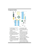
Layout of M7NCD Ultra ※NOTE: ●represents the first pin. 1 - Biostar M7NCD ULTRA | M7NCD Ultra user's manual - Page 4
Slot R. Case Open Connector (JC1) (AGP1) S. IDE Connectors (IDE1-2) G. Front Audio Header (JF_AUDIO1) T. Floppy Disk Connector (FDD1) H. PCI BUS Slots (PCI1-5) U. ATX Power Connector (JATXPWER1) I. CD-ROM Audio-In Header (JCDIN1) V. DIMM Modules (DIMMA1) J. Front Panel Connector (JPANEL1 - Biostar M7NCD ULTRA | M7NCD Ultra user's manual - Page 5
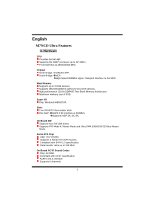
M7NCD Ultra Features A. Hardware CPU Provides Socket-462. Supports the AMD® processor up to XP 3200+. Front Side Bus at 266/333/400 MHz. Chipset North Bridge: nFORCE2 SPP. South Bridge: MCP. High Speed 800Mb/s Hyper-Transport interface to the MCP. Main Memory Supports up to 3 DDR devices. Supports - Biostar M7NCD ULTRA | M7NCD Ultra user's manual - Page 6
1 front audio header. Dimensions ATX Form Factor: 24.4cm X 30.4cm (W X L) B. BIOS & Software BIOS Award legal Bios. APM1.2. ACPI. USB Function. Software Supports CPU SaviorTM, 9th TouchTM, FLASHER™, WinFlasherTM , StudioFun! TM (optional) and WatchdogTM. Offers the highest performance for Windows 98 - Biostar M7NCD ULTRA | M7NCD Ultra user's manual - Page 7
Jumper close Jumper open CPU Installation Pin1-2 close Step1: Pull the lever sideways away from the socket and then raise the lever up to a 90-degree angle. Step2: Look for the white it. Connect the CPU fan power cable to the JCFAN1. This completes the installation. Step1 Step2 Step3 Step4 5 - Biostar M7NCD ULTRA | M7NCD Ultra user's manual - Page 8
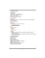
only at 64-bit. DRAM Access Time: 2.5V Unbuffered DDR 266/333/400 MHz Type required. DRAM Type: 64MB/ 128MB/ 256MB/ 512MB/ 1GB DIMM Module (184 pin) Total Memory Size with Unbuffered DIMMs DIMM Socket Location DIMMB1 DIMMB2 DIMMA1 DDR Module 64MB/128MB/256MB/512MB/1GB *1 64MB/128MB/256MB/512MB - Biostar M7NCD ULTRA | M7NCD Ultra user's manual - Page 9
supports the provided floppy drive ribbon cables. Hard Disk Connectors: IDE1/ IDE2 The motherboard has a 32-bit Enhanced PCI IDE Controller that provides PIO Mode 0~4, Bus Master, and Ultra The motherboard has a PCI to SATA Controller with 2 channels SATA interface. It satisfies the SATA 1.0 spec and - Biostar M7NCD ULTRA | M7NCD Ultra user's manual - Page 10
Pin Assignment Pin 65 32 1 Ground 2 3 TX- 4 741 5 RX- 6 JSATA1/ JSATA2 7 Ground Assignment TX+ Ground RX+ Power Connectors: JATXPWER1 PIN Assignment PIN Assignment 10 20 1 +3.3V 11 +3.3V 2 +3.3V 12 -12V 3 Ground 13 Ground 4 +5V 14 PS_ON 5 Ground 15 Ground 1 11 - Biostar M7NCD ULTRA | M7NCD Ultra user's manual - Page 11
16 Ground Button 17 NA 18 KEY 19 NA IrDA 20 KEY IrDA 21 +5V Connector 22 Ground Connector 23 IRTX 24 IRRX Power Source Selection for Keyboard/ Mouse: JKBV1 JKBV1 Assignment Description 3 +5V for keyboard and mouse 1 +5V Pin 1-2 close 3 PS/2 Mouse and PS/2 Keyboard are - Biostar M7NCD ULTRA | M7NCD Ultra user's manual - Page 12
powered with Voltage standby voltage of 5V JUSBV2: JUSBLAN1 port powered with standby voltage of 5V JUSBV4: JUSB2 port powered with standby voltage of 5V Note: 1. In order to power following procedures are for resetting the BIOS password. It is important to follow these instructions closely. 10 - Biostar M7NCD ULTRA | M7NCD Ultra user's manual - Page 13
Channel Input 2 Ground JCDIN1 3 Ground 4 Right Channel Input Front Panel Audio Header: JF_AUDIO1 9 1 10 2 JF_AUDIO1 Pin Assignment Pin Assignment 1 Mic In/ Center 2 Ground 3 Mic Power/ Bass 4 Audio Power 5 Right Line Out/ Speaker 6 Right Line Out/ Speaker Out Right Out - Biostar M7NCD ULTRA | M7NCD Ultra user's manual - Page 14
166/ 200 MHz) Safe mode 1 Pin 1-2 Open (100 MHz) Note: When overclock function failed and system is unable to boot-up, please follow the instruction below: 1. Turn off the system. 2. Closed the JCLK3 jumper. 3. Turn on the system. 4. Enter CMOS setup menu and load defaults settings. 5. Turn off - Biostar M7NCD ULTRA | M7NCD Ultra user's manual - Page 15
M7NCD Ultra A. Hardware CPU Unterstützung für Sockel 462. Unterstützung für den AMD® Prozessor bis zu XP 3200+. FSB mit 266/333/400 MHz. Chipsatz Northbridge: nFORCE2 ATA-Ports (SATA). Entspricht der Spezifikation von SATA 1.0. Datenübertragung und Ultra DMA 33/66/100/133 Bus Master Modus. On-board AC - Biostar M7NCD ULTRA | M7NCD Ultra user's manual - Page 16
ützung für 2 Diskettenlaufwerke.(360KB, 720KB, 1.2MB, 1.44MB und 2.88MB) 4 USB2.0-Ports. 1 Audio-Header für die Vonderseite Abmessungen ATX Form-Factor: 24.4 X 30.4cm (W X L) B. BIOS & Software BIOS Award legal Bios. APM1.2. ACPI. USB Funktion. Software Unterstützung für CPU SaviorTM, 9th TouchTM - Biostar M7NCD ULTRA | M7NCD Ultra user's manual - Page 17
Einstellung der Jumper Die Abbildung verdeutlicht, wie Jumper eingestellt werden. Pins werden durch die Jumper-Kappe verdeckt, ist der Jumper "geschlossen". Keine Pins werden durch die Jumper-Kappe verdeckt, ist der Jumper "geöffnet". Die Abbiildung zeigt einen 3-Pin Jumper dessen Pin1 und Pin2 " - Biostar M7NCD ULTRA | M7NCD Ultra user's manual - Page 18
CPU-Lüfter Headers: JCFAN1 1 Pin 1 2 JCFAN1 3 Belegung Masse +12V Sensor System-Lüfter Headers: JSFAN1 Pin 1 1 2 JSFAN1 3 Belegung Masse +12V Sensor Northbridge-Lüfter Header: JNFAN1 Pin 1 1 JNFAN1 2 Belegung Masse +12V DDR-DIMM-Modules: DIMMB1-2, DIMMA1 Für Dual-Kanal DDR (128 - Biostar M7NCD ULTRA | M7NCD Ultra user's manual - Page 19
32-Bit Enhanced PCI IDE-Controller, der die Modi PIO0~4, Bus Master sowie die Ultra DMA/33/66/100/133- Funktion zur Verfügung stellt. Dieser ist mit zweii : AGP1 Ihr Monitor wird direkt an die Grafikkarte angeschlossen. Dieses Motherboard unterstützt Grafikkarten für PCI-Slots, aber es ist auch mit - Biostar M7NCD ULTRA | M7NCD Ultra user's manual - Page 20
ATA-Kanal für bis zu zwei Geräte. Es entspriecht der Speczifikation von SATA 1.0. 65 32 Pin Belegung Pin 1 Masse 2 Belegung TX+ 3 TX- Anschluss 22 Masse 23 IRTX 24 IRRX Funktion Schlafen- Knopf Kein PowerLED Power-On Knopf Kein Pin IrDA Anschluss Front USB Header: JUSB1/2 Pin - Biostar M7NCD ULTRA | M7NCD Ultra user's manual - Page 21
geschlossen 5V für Tastatur und Maus 1 3 Pin 2-3 geschlossen +5V reservierte PS/2-Maus und PS/2-Tastatur werden durch Spannung 5V reservierte Spannung aktiviert Anmerkung: Um die "power-on by Keyboard and Mouse" Funktion zu behandeln, sollen Pin2-3 durch die Jumperkappe verdeckt werden. 19 - Biostar M7NCD ULTRA | M7NCD Ultra user's manual - Page 22
JUSBV4: JUSB2 ist aktiviert durch die reservierte 5V Spannang Anmerkung: 1. Um die "power-on by USB-Geräte" Funktion zu behandeln, sollen pin2-3 von JUBV1/ JUBV2 -Daten Löschen Die folgende Schritte leiten Sie, das Kennwort für BIOS-System zurückzusetzen. Es ist wichtig, die Anweisung zu folgen. 20 - Biostar M7NCD ULTRA | M7NCD Ultra user's manual - Page 23
2 3 Mikrofon-Betriebsspannung 4 5 Recht Line-Out 6 7 Reserviert 8 9 Link Line-Out 10 *Reserviert: Nicht in Gebrauch Digital Audio Anschluss: J_SPDIF1 Belegung Masse Audio-Spannung Recht Line-Out Schlüsse Link Line-Out 1 Pin 1 2 J_SPDIF1 3 Belegung +5V SPDIF_Ausgang Masse 21 - Biostar M7NCD ULTRA | M7NCD Ultra user's manual - Page 24
System Operation Modus: JCLK3 JCLK3 Assignment 1 Pin 1-2 Geöffnet Benutzer Modus (default) (133/ 166 MHz) Sicherheit Modus 1 Pin 1-2 Geschlossen (100 MHz) Anmerkung: Wenn "Überspanng Funktion" nicht gelungen ist folgen Sie bitte die Instruktion darunter: 1. Bitte vausschalton Sie den AC- - Biostar M7NCD ULTRA | M7NCD Ultra user's manual - Page 25
the system can be at a vulnerable state. Therefore, the BIOSTAR Watchdog Technology was designed to protect your PC under dangerous over-clock from rebooting in the BIOS setting. Under this circumstance, please power off your PC. After that, press and power on your system simultaneously - Biostar M7NCD ULTRA | M7NCD Ultra user's manual - Page 26
like flash disks and USB floppy disks. Hardware Requirements The supported hardware list of StudioFun! grows up every day. So please check the hwreq.txt located in the root of StudioFun! Installation CD to get the most updated information. Installation Procedure Insert the StudioFun! Installation CD - Biostar M7NCD ULTRA | M7NCD Ultra user's manual - Page 27
required and waits for a confirmation. Selecting Ok will continue the installation while selecting Cancel will terminate the installation and reboot the machine. If Windows the DVD area/region selection code. Choose this based on the installed. The distribution currently supports PS/2, USB and Serial - Biostar M7NCD ULTRA | M7NCD Ultra user's manual - Page 28
Recovery In case of a MBR corruption, this option should be used. It will automatically probe the hard disk master boot record and find out the installed operating system(s). On success it will re-install the boot loader with correct options in the MBR. Any custom boot loader option specified from - Biostar M7NCD ULTRA | M7NCD Ultra user's manual - Page 29
After complete boot up, you get to the main Desktop screen. The following section is a complete description of the Desktop application. Desktop This is the main shell of the StudioFun software. It basically comprises of two categories, one is the main "media control" part and the other is the " - Biostar M7NCD ULTRA | M7NCD Ultra user's manual - Page 30
and running, otherwise, the control will simply glow to inform the user about a AUDIO present in the DVD/CD-ROM drive. 5. FILE This control will glow whenever a eject the default DVD/CD-ROM drive. 7. EXIT This is the "Power on/off" control of the Desktop (StudioFun! shell). Control Panel Control - Biostar M7NCD ULTRA | M7NCD Ultra user's manual - Page 31
1. Select Region Clicking this icon will invoke the application for selection DVD region settings. Refer to section 5.2 Select DVD Region application for more details. 2. Screensaver Clicking this icon will invoke the screensaver application. Refer to section 5.3 Screensaver for more details. 3. - Biostar M7NCD ULTRA | M7NCD Ultra user's manual - Page 32
subtitles e. DVD/VCD menus (requires external plugin) f. Audio and subtitle channel selection g. Closed Caption support h. Brightness, contrast, audio volume, hue, saturation adjusting requires hardware/driver support) i. Playlists j. Image snapshot k. Audio resampling l. Software de-interlacing - Biostar M7NCD ULTRA | M7NCD Ultra user's manual - Page 33
f. MPEG-Video (.mpv, .m2v) g. MPEG-Audio (.mp2, .mp3) h. WAV (.wav) Video Codecs i. MPEG 1/2 j. MPEG 4 (aka OpenDivX) k. MS MPEG 4 a. Chapter 5: Software Details 10 l. Windows Media Video 7 m. Motion JPEG • Remote Control support. a. Infrared interface b. User-friendly • Usage of StudioFun! with - Biostar M7NCD ULTRA | M7NCD Ultra user's manual - Page 34
l. j. Select hide button to hide the control panel of the player m. k. Select menu button to use menu's while playing DVD n. l. Select control button to adjust brightness / color o. Select setup button to modify the settings of the player p. Select f.scr button to show the video output of the player - Biostar M7NCD ULTRA | M7NCD Ultra user's manual - Page 35
Screensaver Screensaver The xscreensaver daemon waits until the keyboard and mouse have been idle for a period, and then runs a graphics demo chosen at random. The demo is terminated as soon as there is any mouse or keyboard activity. The xscreensaver-demo program is the graphical user interface to - Biostar M7NCD ULTRA | M7NCD Ultra user's manual - Page 36
2. Only one Screen Saver: When user chooses this option, screensaver displays only one graphics demo. 3. Blank Screen Only: When user chooses this option, screensaver only blanks the screen instead of displaying the graphics demo. 4. Disable Screen Saver: When user chooses this option, screensaver - Biostar M7NCD ULTRA | M7NCD Ultra user's manual - Page 37
three resolutions. • 640x480 • 800x600 • 1024x768 The current resolution of the Display will be selected by default. It requires restart of the StudioFun to reflect the changes made. File Manager Overview File manger is an utility to copy files from deferent devices to hard - Biostar M7NCD ULTRA | M7NCD Ultra user's manual - Page 38
36 - Biostar M7NCD ULTRA | M7NCD Ultra user's manual - Page 39
Trouble Shooting PROBABLE SOLUTION No power to the system at all Power light don't * Make sure power cable is securely plugged in illuminate, fan inside power supply does not on. Indicator light on keyboard does not turn turn on * Replace cable * Contact technical support * Review system's - Biostar M7NCD ULTRA | M7NCD Ultra user's manual - Page 40
Problemlösung MÖGLICHE URSACHE LÖSUNG Das System hat keine Spannungsversorgung. * Versichern Sie sich, dass das Stromkabel richtig Die Stromanzeige leuchtet nicht, der Lüfter im angebracht ist Inneren der eingeschaltet. Stromversorgung Tastaturleuchten sind wird nicht nicht an. * Ersetzen - Biostar M7NCD ULTRA | M7NCD Ultra user's manual - Page 41
09/29/2003 39
-
 1
1 -
 2
2 -
 3
3 -
 4
4 -
 5
5 -
 6
6 -
 7
7 -
8
-
9
-
10
-
11
-
12
-
13
-
14
-
15
-
16
-
17
-
18
-
19
-
20
-
21
-
22
-
23
-
24
-
25
-
26
-
27
-
28
-
29
-
30
-
31
-
32
-
33
-
34
-
35
-
36
-
37
-
38
-
39
-
40
-
41
 |
 |

M
M
7
7
N
N
C
C
D
D
U
U
l
l
t
t
r
r
a
a
i
FCC Information and Copyright
This equipment has been tested and found to comply with the limits of a
Class B digital device, pursuant to Part 15 of the FCC Rules. These limits
are designed to provide reasonable protection against harmful
interference in a residential installation. This equipment generates, uses
and can radiate radio frequency energy and, if not installed and used in
accordance with the instructions, may cause harmful interference to radio
communications. There is no guarantee that interference will not occur in
a particular installation.
The vendor makes no representations or warranties with respect to the
contents here of and specially disclaims any implied
warranties
of
merchantability or fitness for any purpose. Further the vendor reserves
the right to revise this publication and to make changes to the contents
here of without obligation to notify any party beforehand.
Duplication of this publication, in part or in whole, is not allowed without
first obtaining the vendor’s approval in writing.
The content of this user’s manual is subject to be changed without notice
and we will not be responsible for any mistakes found in this user’s
manual. All the brand and product names are trademarks of their
respective companies.