Biostar M7SXD M7SXD user's manual
Biostar M7SXD Manual
 |
View all Biostar M7SXD manuals
Add to My Manuals
Save this manual to your list of manuals |
Biostar M7SXD manual content summary:
- Biostar M7SXD | M7SXD user's manual - Page 1
M7SXD Federal to ensure compliance with FCC Rules. It is the responsibility of the user to provide and use these accessories properly. This equipment has been tested you did not installed and used in accordance with the instructions, may cause harmful interference in the radio communications. There - Biostar M7SXD | M7SXD user's manual - Page 2
Remarks MS-DOS, Windows, Windows NT, Windows 9X, Windows ME, Windows XP and Windows 2000 are products of Microsoft Corp, with its ownership of the vendor under a license agreement. All trademarks used in this manual are property of their respective owners. Copyright© 2001 All Rights Reserved - Biostar M7SXD | M7SXD user's manual - Page 3
1.1.1 Hardware...1-2 1.1.2 BIOS ...1-5 1.1.3 Software...1-5 1.1.4 Accessories ...1-5 1.2 Motherboard Installation 1-6 1.2.1 System Block Diagram 1-6 1.2.2 Layout of Motherboard 1-7 1.2.3 Quick Reference 1-8 1.3 CPU Installation 1-9 1.3.1 CPU Installation Procedure: Socket 478 1-9 1.3.2 CPU Fan - Biostar M7SXD | M7SXD user's manual - Page 4
27 1.7.3.2 Parallel Interface Port: JPRNT1 1-29 1.7.4 Game (Joystick/MIDI) Port Connector: JAUD_GAME1 1-30 1.7.5 Audio Port Connectors: JSPKR1/JLIN1/JMIC1 1-30 1.7.6 Audio Subsystem 1-31 1.7.6.1 CD-ROM Audio-In Header: JCDIN1 1-32 1.7.6.2 CD-ROM Audio-In Header: JCDIN2 1-32 1.7.6.3 Front Panel - Biostar M7SXD | M7SXD user's manual - Page 5
BIOS Setup 2-1 2.1 Main Menu 2-3 2.2 Standard CMOS Features 2-6 2.3 Advanced BIOS Features 2-9 2.4 Advanced Chipset Features 2-13 2.5 Integrated Peripherals 2-15 2.6 Power Management Setup 2-21 2.7 PnP/PCI Configurations 2-24 2.8 PC Health Status 2-27 2.9 Frequency Control 2-29 3. Trouble - Biostar M7SXD | M7SXD user's manual - Page 6
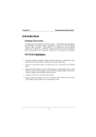
standards. M7SXD Highlights: 8 Contains on board I/O facilities, which include two serial ports, a parallel port, a PS/2 mouse port, a PS/2 keyboard port, audio ports, USB ports, a game port. 8 Contains on board IDE facilities for IDE devices such as hard disks and CD-ROM Drives. 8 Supports the - Biostar M7SXD | M7SXD user's manual - Page 7
400 MHz Front Side Bus frequency. Supports up to 2.2 GHz CPU core speeds. The 33MHz 32 bit PCI 2.2 compliant. The 66MHz AGP 2.0 compliant interface supports 1x, 2x and 4x data transfer mode. Chipset − SiS 645/ SiS 961. − Winbond W83697HF. DRAM Memory − Supports 200MHz, 266MHz or 333MHz DDR SDRAM - Biostar M7SXD | M7SXD user's manual - Page 8
33, Ultra DMA 66, Ultra DMA 100 Bus Master Modes. − Supports IDE interface with CD-ROM. − Supports high capacity hard disk drives. − Supports LBA mode. AC'97 Sound Codec Onboard − AC-LINK protocol compliance. − Compliant with AC'97 2.2 specification. − 18-bit full duplex stereo ADC, DACs. − SNR>95 - Biostar M7SXD | M7SXD user's manual - Page 9
1 Motherboard Description I/O facilities − One multi-mode Parallel Port capable of supporting the following specifications: Standard & Bidirection Parallel Port. Enhanced Parallel Port (EPP). Extended Capabilities Port (ECP). Normal − Supports two serial ports, 16550 UART. − Supports Infrared - Biostar M7SXD | M7SXD user's manual - Page 10
performance for MS-DOS, Windows NT, Windows 2000, Windows 95/98, Windows ME, Windows XP, Novell, SCO UNIX etc. 1.1.4 Accessories − HDD Cable. − FDD Cable. − Flash Memory Writer for BIOS Update. − JUSB1/JUSB2 Cable (Optional). − Rear I/O Panel for ATX Case (Optional). − Fully Setup Driver CD. 1-5 - Biostar M7SXD | M7SXD user's manual - Page 11
Out 3D Audio Out MII USB 2 USB 4 USB 5 FAN FAN 12 Legacy ROM FAN CONTROL FAN CONTROL LPC Super I/O VOLTAGE MONITOR TEMPERATURE MONITOR GPIOs IR/CIR GAME/MIDI SERIAL PARALLEL FLOPPY M7SXD ATX(FSB: 400MHz) SUPPORTS 2DDR or 2SDR DIMMS SUPPORTS 1 AGP SLOT SUPPORTS 5 PCI SLOTS SUPPORTS 1 ACR SLOT - Biostar M7SXD | M7SXD user's manual - Page 12
Description 1.2.2 Layout of Motherboard Model No. M7SXD JKBMS1 J AT X P W R 2 JCFAN1 Socket 478 JCOM1 JPRNT1 DDR 1 DDR 2 SDR1 SDR2 JCOM2 SP-OUT JAUD_GAME1 GAME Port LINE-IN MIC-IN 2 1 JAUDIO1 LAN CHIP JCDIN1 11 1 JCDIN2 JTAD1 BIOS Winbond I/O JAUXPWR1 AGP1 PCI1 SDR1 - Biostar M7SXD | M7SXD user's manual - Page 13
B BIOS H LAN CHIP Wi nb on d I/O Motherboard Description A Z Y Socket 478 SiS 961 USB 2.0 I J K L PRIMARY IDE CONN. M SECONDARY IDE CONN. FLOPPY DISK CONN. X DDR 1 W DDR 2 SDR1 V SDR2 NO P Q A. Back Panel I/O Connectors RS T U O. Front USB Header (JUSB2) B. Front Audio Header - Biostar M7SXD | M7SXD user's manual - Page 14
Chapter 1 Motherboard Description 1.3 CPU Installation 1.3.1 CPU Installation Procedure: Socket 478 CPU 1. Pull the lever sideways away from the socket then raise the lever up to 90-degree angle. 2. Locate Pin A in the socket and look for the white dot or cut edge in the CPU. Match Pin A with - Biostar M7SXD | M7SXD user's manual - Page 15
Chapter 1 Motherboard Description CPU Installation Layout Socket 478 J C FA N 1 DDR 1 DDR 2 SDR1 SDR2 LAN CHIP SiS 961 PRIMARY IDE CONN. SECONDARY IDE CONN. FLOPPY DISK CONN. BIOS Winbond I/O USB 2.0 JSFAN1 1.3.2 CPU Fan Header: JCFAN1 Pin No. 1 2 3 Assignment Ground +12V Sense 1.3.3 - Biostar M7SXD | M7SXD user's manual - Page 16
1 Motherboard Description 1.4 RAM Module Installation 1.4.1 DDR SDRAM DRAM Access Time: 2.5V Unbuffered DDR SDRAM (without ECC) PC1600/ PC2100/ PC2700 Type required. DRAM Type: 128MB/ 256MB/ 512MB/ 1GB DIMM Module (184 pin) Total Memory Size with unbuffer DIMMs (Only for reference) Total Memory - Biostar M7SXD | M7SXD user's manual - Page 17
Chapter 1 Motherboard Description 1.4.2 SDRAM DRAM Access Time: 3.3V Unbuffered SDRAM (without ECC) PC100/ PC133 Type required. DRAM Type: 128MB/ 256MB/ 512MB DIMM Module (168 pin) Total Memory Size with unbuffer DIMMs (Only for reference) Total Memory DIMM 1 DIMM 2 Size (MB) 128 M 256 M 512 - Biostar M7SXD | M7SXD user's manual - Page 18
Chapter 1 Motherboard Description 1.4.3 How to install DDR/SDRAM DIMM Module DDR SDRAM: Single Sided DIMM Double Sided DIMM 1. The DDR DIMM socket has a " Plastic Safety Tab", and the DDR DIMM memory module has an Asymmetrical notch", so the DDR DIMM memory module can only fit into the slot in - Biostar M7SXD | M7SXD user's manual - Page 19
Chapter 1 SDRAM: Motherboard Description 1. The SDRAM DIMM socket has a " Plastic Safety Tab", and the SDRAM DIMM memory module has an Asymmetrical notch", so the SDRAM DIMM memory module can only fit into the slot in one direction. 2. Push the tabs out. Insert the SDRAM DIMM memory modules into - Biostar M7SXD | M7SXD user's manual - Page 20
these efficient facilities, you can increase the motherboard's capabilities by adding hardware that performs tasks that are not part of the basic system. Socket 478 DDR 1 DDR 2 SDR1 SDR2 PRIMARY IDE CONN. SECONDARY IDE CONN. FLOPPY DISK CONN. AGP Slot LAN CHIP BIOS PCI Slots ACR Slot CNR Slot - Biostar M7SXD | M7SXD user's manual - Page 21
Network Riser) Slot The CNR specification is an open Industry Standard Architecture, and it defines a hardware scalable riser card interface, which supports audio, network and modem only. 1.5.4 PCI (Peripheral Component Interconnect) Slots This motherboard is equipped with 5 standard PCI - Biostar M7SXD | M7SXD user's manual - Page 22
Chapter 1 Motherboard Description 1.6 Connectors, Headers & Jumpers The connectors, headers and JAUXPWR1 J AT X P W R 1 LAN CHIP JDIMMPWR1 SiS 961 PRIMARY IDE CONN. SECONDARY IDE CONN. FLOPPY DISK CONN. BIOS Winbond I/O USB 2.0 JWOL1 USB20B1 JPANEL1 JCMOS1 USB20A1 1-17 JUSB2 JUSB1 - Biostar M7SXD | M7SXD user's manual - Page 23
It can be connected to the motherboard at the front panel connector. The speaker (onboard or offboard) provides error beep code information during the Power On Self-Test when the computer cannot use the video interface. The speaker is not connected to the audio subsystem and does not receive output - Biostar M7SXD | M7SXD user's manual - Page 24
This switch is usually open, and when it is closed, it will cause the motherboard to reset and run the POST (Power On Self Test). POW-LED (Power again. APM (Advanced Power Management) must be enabled in the system BIOS and the APM driver must be loaded. ON/OFF (Power Button) This connector can be - Biostar M7SXD | M7SXD user's manual - Page 25
power button on-board. Using the ATX power supply function, such as Soft Power Off is supported on this motherboard. This power connector supports instant power-on functionality, which means that the system will boot up instantly when the power connector is inserted on the board. PIN Assignment - Biostar M7SXD | M7SXD user's manual - Page 26
hard disk drives, a CD-ROM, a 120MB Floppy (reserved for future BIOS) and other devices to IDE1 and IDE2. These connectors support the IDE hard disk . 1.6.6 Floppy Disk Connector: FDD1 The motherboard provides a standard floppy disk connector (FDC) that supports 360K, 720K, 1.2M, 1.44M and - Biostar M7SXD | M7SXD user's manual - Page 27
Closed 1 3 2-3 Closed Assignment Normal Operation (default) Clear CMOS Data The following procedures are for resetting the BIOS password. It is important to follow these instructions closely. Remove AC power line JCMOS1 (2-3) closed Wait five seconds JCMOS1 (1-2) closed AC power on Reset - Biostar M7SXD | M7SXD user's manual - Page 28
Chapter 1 Motherboard Description 1.6.9 Front USB Headers: JUSB1/JUSB2 & USB20A1/USB20B1 (Optional) Note: Before you install these two headers, make sure the pin assignments are corresponded to the - Biostar M7SXD | M7SXD user's manual - Page 29
Chapter 1 Motherboard Description (USB20A1)(Optional) Pin Assignment 1 +5V 3 USB1 Data(-) 5 USB1 Data(+) 7 Ground 9 KEY Pin Assignment 2 +5V 4 USB2 Data(-) 6 USB2 Data(+) 8 Ground 10 NC (USB20B1)(Optional) Pin - Biostar M7SXD | M7SXD user's manual - Page 30
Game Port PS/2 Keyboard USB COM1 JCOM1 COM2 JCOM2 Speaker Line In Mic Out In 1.7.1 PS/2 Mouse / Keyboard Connector: JKBMS1 The motherboard provides a standard PS/2 mouse / Keyboard mini DIN connector for attaching a PS/2 mouse. You can plug a PS/2 mouse / Keyboard directly into this - Biostar M7SXD | M7SXD user's manual - Page 31
Description 1.7.2 USB & LAN Connectors: JUSBLAN1 (Optional) The motherboard provides a OHCI (Open Host Controller Interface) Universal Serial Bus Roots for attaching USB devices such as: keyboard, mouse and other USB devices. You can plug - Biostar M7SXD | M7SXD user's manual - Page 32
Chapter 1 Motherboard Description 1.7.3 Serial and Parallel Interface Ports This system comes equipped with two serial ports and one parallel port. Both types of interface ports will be - Biostar M7SXD | M7SXD user's manual - Page 33
Chapter 1 Motherboard Description Connectivity The serial ports can be used in many ways, and it may be necessary to become familiar with the pinout diagram. The following - Biostar M7SXD | M7SXD user's manual - Page 34
Chapter 1 Motherboard Description 1.7.3.2 Parallel Interface Port: JPRNT1 Unlike the serial ports, parallel interface port has been standardized and should not present any difficulty interfacing peripherals to your - Biostar M7SXD | M7SXD user's manual - Page 35
JMIC1 Speaker Out is used to connect speakers or headphones for audio output. Line In can be connected to the external CD player, Tape player or other audio devices for audio input. Mic In is used to connect a microphone which allows you to input sounds and voices. Speaker Out Line In Mic In 1-30 - Biostar M7SXD | M7SXD user's manual - Page 36
Chapter 1 1.7.6 Audio Subsystem Motherboard Description DDR 1 DDR 2 SDR1 SDR2 PRIMARY IDE CONN. SECONDARY IDE CONN. FLOPPY DISK CONN. LAN CHIP JAUDIO1 JCDIN1 JCDIN2 SiS 961 USB 2.0 JTAD1 1-31 - Biostar M7SXD | M7SXD user's manual - Page 37
1 Motherboard Description 1.7.6.1 CD-ROM Audio-In Header: JCDIN1 Pin No. 1 2 3 4 Assignment Left Channel Input Ground Ground Right Channel Input 1.7.6.2 CD-ROM Audio-In Header: JCDIN2 Pin No. 1 2 3 4 Assignment Left Channel Input Ground Right Channel Input Ground 1.7.6.3 Front Panel Audio - Biostar M7SXD | M7SXD user's manual - Page 38
this manual is intended to guide you through the process of configuring your system using Setup. Plug and Play Support These AWARD BIOS supports the Plug and Play Version 1.0A specification. ESCD (Extended System Configuration Data) write is supported. EPA Green PC Support This AWARD BIOS supports - Biostar M7SXD | M7SXD user's manual - Page 39
Version 2.1 of the Intel PCI (Peripheral Component Interconnect) local bus specification. DRAM Support DDR SDRAM supported. Supported CPUs This AWARD BIOS supports the Intel Pentium® 4 (Socket 478) processor. Using Setup In general, you use the arrow keys to highlight items, press to - Biostar M7SXD | M7SXD user's manual - Page 40
> to accept and enter the sub-menu. !! WARNING !! The information about BIOS defaults on manual (Figure 1,2,3,4,5,6,7,8,9) is just for reference, please refer to the BIOS installed on board, for update information. Figure 1. Main Menu Standard CMOS Features This submenu contains industry standard - Biostar M7SXD | M7SXD user's manual - Page 41
clock ratio, you should check your CPU frequency in advance. The CPU clock ratio should be changed depending on your CPU frequency.) Load Optimized Defaults This selection allows you to reload the BIOS when the system is having problems particularly with the boot sequence. These configurations are - Biostar M7SXD | M7SXD user's manual - Page 42
all configuration changes to CMOS(memory) and exit setup. message will be displayed before proceeding. confirmation Exit Without Saving Abandon all changes made during the current session and exit setup. confirmation message will be displayed before proceeding. Update BIOS This submenu allows you - Biostar M7SXD | M7SXD user's manual - Page 43
Chapter 2 BIOS Setup 2.2 Standard CMOS Features The items in Standard CMOS Setup Menu are divided into 10 categories. Each category includes no, one or more than one - Biostar M7SXD | M7SXD user's manual - Page 44
Chapter 2 BIOS Setup Main Menu Selections This table shows the selections that you can make on the Main Menu. Item Options Description Date MM DD YYYY Set - Biostar M7SXD | M7SXD user's manual - Page 45
, but Diskette All, but Disk/ Key N/A N/A N/A Description Select the situation in which you want the BIOS to stop the POST process and notify you. Displays the amount of conventional memory detected during boot up. Displays the amount of extended memory detected during boot up. Displays the total - Biostar M7SXD | M7SXD user's manual - Page 46
to the boot sector, BIOS will display a warning message on the screen and sound an alarm beep. Disabled (default) Enabled Virus protection is disabled. Virus protection is activated. CPU L1 & L2 Cache Depending on the CPU/chipset in use, you may be able to increase memory access time with this - Biostar M7SXD | M7SXD user's manual - Page 47
Chapter 2 BIOS Setup CPU L2 Cache ECC Checking This item allows you to enable/disable CPU L2 Cache ECC Checking. The Enable quick POST. Disabled Normal POST. First /Second/Third/ Boot Other Device These BIOS attempts to load the operating system from the devices in the sequence selected in these - Biostar M7SXD | M7SXD user's manual - Page 48
Chapter 2 BIOS Setup Gate A20 Option Select if chipset or keyboard controller should control Gate A20. Normal A pin in are set from the Setup main menu. APIC Mode Selecting Enabled APIC device mode reporting from the BIOS to the operating system. The Choices: Disabled (default), Enabled. 2-11 - Biostar M7SXD | M7SXD user's manual - Page 49
The BIOS supports version 1.1 and 1.4 of the Intel multiprocessor specification. Select the version supported by the operation system running on this computer. The Choices: 1.4 (default), 1.1. OS Select For DRAM > 64MB A choice other than Non-OS2 is only used for OS2 systems with memory exceeding - Biostar M7SXD | M7SXD user's manual - Page 50
Chapter 2 BIOS Setup 2.4 Advanced Chipset Features This submenu allows you to configure the specific features of the chipset installed on your system. This chipset manages bus speeds and access to system memory resources, such as DRAM and external cache. It also coordinates communications with the - Biostar M7SXD | M7SXD user's manual - Page 51
Chapter 2 BIOS Setup CAS Latency Setting When synchronous DRAM is installed, the number When enabled, you can reserve an area of system memory for ISA adapter ROM. When this area is reserved , it cannot be cached. Refer to the user documentation of the peripheral you are installing for more - Biostar M7SXD | M7SXD user's manual - Page 52
2.5 Integrated Peripherals Figure 5. Integrated Peripherals BIOS Setup SIS OnChip IDE Device If you highlight a PIO mode (0-4) for each of the IDE devices that the onboard IDE interface supports. Modes 0 through 4 provide successively increased performance. In Auto mode, the system automatically - Biostar M7SXD | M7SXD user's manual - Page 53
driver (Windows 95 OSR2 or a third party IDE bus master driver). If your hard drive and your system software both support Ultra DMA/100, select Auto to enable BIOS support following options: SIS-7012 AC97 AUDIO This option allows you to control the onboard AC97 audio. The Choices: Enabled (default), - Biostar M7SXD | M7SXD user's manual - Page 54
Chapter 2 BIOS Setup Onboard FDC Controller Select Enabled if your system has a floppy disk controller (FDC) installed on the system board and you wish to use it. - Biostar M7SXD | M7SXD user's manual - Page 55
Chapter 2 BIOS Setup Use IR Pins Consult your IR peripheral documentation to select the correct setting of the TxD and RxD signals. The Choices: IR-Rx2Tx2 (default), - Biostar M7SXD | M7SXD user's manual - Page 56
Chapter 2 BIOS Setup USB Controller This option should be enabled if your system has a USB installed on the system board. You will need to disable this feature if you add a higher performance controller. The Choices: Enabled (default), Disabled. USB Keyboard Support Enables support for USB - Biostar M7SXD | M7SXD user's manual - Page 57
Chapter 2 BIOS Setup USB1 Access Interface This item allows you select the USB1 Access Interface. The Choices: Embedded Bus (default), PCI Bus. USB0 Access Interface This item allows you select the USB0 Access Interface. The Choices: Embedded Bus (default), PCI Bus. Audio Access Interface This - Biostar M7SXD | M7SXD user's manual - Page 58
Chapter 2 BIOS Setup 2.6 Power Management Setup The Power Management Setup Menu allows you to configure your system to utilize energy conservation and power up/power down features. - Biostar M7SXD | M7SXD user's manual - Page 59
Chapter 2 BIOS Setup Video Off Option This field determines when to activate the video off to the video buffer. Blank Screen This option only writes blanks to the video buffer. DPMS Support (default) Initial display power management signaling. Switch Function You can choose whether or not to - Biostar M7SXD | M7SXD user's manual - Page 60
Chapter 2 BIOS Setup Power Button Override When you select Enabled, pressing the power button for more than 4 seconds forces the system to enter the Soft-Off state - Biostar M7SXD | M7SXD user's manual - Page 61
which resources are assigned to it. The system needs to record and update ESCD to the memory locations. These locations (4K) are reserved in the system BIOS. If the Disabled (default) option is chosen, the system's ESCD will update only when the new configuration varies from the last one. If the - Biostar M7SXD | M7SXD user's manual - Page 62
system BIOS will detect the system resources and automatically assign the relative IRQ and DMA channel for each peripheral. By Choosing "Manual", the user will their display as a way to provide boot information and VGA compatibility. However, the color information coming from the VGA controller - Biostar M7SXD | M7SXD user's manual - Page 63
Chapter 2 BIOS Setup In this case, the PCI VGA controller should not respond to the Write, it should only snoop the data and permit the access to - Biostar M7SXD | M7SXD user's manual - Page 64
Figure 8. PC Health Status BIOS Setup CPU Warning Temperature This item allows you to set the warning temperature of the CPU in order not to be damaged by the overheated temperature. When this function is enabled, the system will warn you if the CPU temperature reaches the warning temperature - Biostar M7SXD | M7SXD user's manual - Page 65
BIOS Setup CPU Voltage 3.3V, +5V, +12V Detect the system's voltage status automatically. Shutdown Temperature This item allows you to set the shutdown temperature of the CPU enabled, the system will automatically shutdown if the CPU temperature reaches the shutdown temperature. This function only - Biostar M7SXD | M7SXD user's manual - Page 66
Chapter 2 2.9 Frequency Control Figure 9. Frequency Control BIOS Setup CPU Clock Ratio This item allows you to select the CPU Ratio. The Choices: 0X (default), X8, X9, X10~ X50. Auto Detect DIMM/PCI Clk This item allows you to enable/disable auto Detect DIMM/PCI - Biostar M7SXD | M7SXD user's manual - Page 67
Chapter 2 BIOS Setup CPU Host/SDRAM/PCI Clock This item allows you to select CPU Host/SDRAM/PCI Clock. The Choices: SDRAM by SPD (default), 100/100/33 MHz, 100/133/33 MHz, 100/166/33 MHz, 105/140/35 - Biostar M7SXD | M7SXD user's manual - Page 68
Trouble Shooting 3. Trouble Shooting PROBLEM Contact technical support. socket are PROBLEM System inoperative. Keyboard lights are on, power indicator lights are lit, hard drive is spinning. PROBABLE CAUSE DIAGNOSIS SOLUTION Memory DIMM is partially dislodged from the slot on the motherboard - Biostar M7SXD | M7SXD user's manual - Page 69
Trouble Shooting PROBLEM System does not boot from hard disk drive, can be booted from CD SPECIFICATION. ends are securely plugged in; check the drive type in the standard CMOS setup. Damaged hard disk or disk controller. Format hard disk; if Contact technical unable to do so the hard support - Biostar M7SXD | M7SXD user's manual - Page 70
3 Trouble Shooting PROBLEM Error hard drive. Re-install all saved data when completed. PROBLEM Screen message says "Invalid Configuration" or "CMOS Failure No power to monitor. Monitor not connected to computer. PROBLEM DIAGNOSIS SOLUTION Check the power connectors to monitor and to system - Biostar M7SXD | M7SXD user's manual - Page 71
Chapter 3 Trouble Shooting No screen. PROBLEM PROBABLE CAUSE Memory problem. Computer virus. DIAGNOSIS SOLUTION Reboot computer. Reinstall memory, make sure that all memory modules are installed in correct sockets. Use anti-virus programs to detect and clean viruses. PROBLEM Screen goes blank - Biostar M7SXD | M7SXD user's manual - Page 72
Call technical support. C: drive failure. PROBLEM PROBABLE CAUSE Hard drive cable not connected properly. DIAGNOSIS SOLUTION Check hard drive cable. PROBLEM Cannot boot system after installing second hard drive. PROBABLE CAUSE Master/slave jumpers not set correctly. Hard drives not compatible - Biostar M7SXD | M7SXD user's manual - Page 73
Chapter 3 Trouble Shooting PROBLEM Missing operating system on hard drive. PROBABLE CAUSE CMOS setup has been changed. DIAGNOSIS SOLUTION Run setup and select correct drive type. PROBLEM Certain keys do not function. PROBABLE CAUSE Keys jammed or defective. DIAGNOSIS SOLUTION Replace - Biostar M7SXD | M7SXD user's manual - Page 74
12/26/2001 MADE IN TAIWAN R.O.C.
-
 1
1 -
 2
2 -
 3
3 -
 4
4 -
 5
5 -
 6
6 -
 7
7 -
8
-
9
-
10
-
11
-
12
-
13
-
14
-
15
-
16
-
17
-
18
-
19
-
20
-
21
-
22
-
23
-
24
-
25
-
26
-
27
-
28
-
29
-
30
-
31
-
32
-
33
-
34
-
35
-
36
-
37
-
38
-
39
-
40
-
41
-
42
-
43
-
44
-
45
-
46
-
47
-
48
-
49
-
50
-
51
-
52
-
53
-
54
-
55
-
56
-
57
-
58
-
59
-
60
-
61
-
62
-
63
-
64
-
65
-
66
-
67
-
68
-
69
-
70
-
71
-
72
-
73
-
74
 |
 |

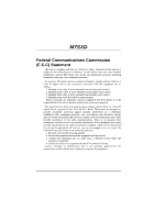
M7SXD
Federal Communications Commission
(F.C.C) Statement
This device complies with Part 15 of the FCC Rules. Operation of this device is
subject to the following two conditions: (1) this device may not cause harmful
interference, and (2) this device must accept any interference received, including
interference that may cause undesired operation.
Accessories: This device has been tested and found to comply with the limits of a
Class B digital device; the accessories associated with this equipment are as
follows:
1. Shielded serial cable. (Can be obtained from multiple retail outlets)
2. Shielded printer cable. (Can be obtained from multiple retail outlets)
3. Shielded video cable. (Can be obtained from multiple retail outlets)
4. Shielded power cord. (Provided by manufacturer)
These accessories are required to ensure compliance with FCC Rules. It is the
responsibility of the user to provide and use these accessories properly.
This equipment has been tested and found to comply with the limits of a Class B
digital device, pursuant of Part 15 of the FCC Rules. These limits are designed to
provide reasonable protection against harmful interference in a residential
installation. This equipment generates, uses and radiates radio frequency energy
and, if you did not installed and used in accordance with the instructions, may cause
harmful interference in the radio communications. There is no guarantee that
interference will not occur in a particular installation. If this equipment does cause
harmful interference in the radio or television reception, which can be determined
by turning the equipment off and on, you are encouraged to try to correct the
interference by one or more of the following measures:
1. Reorient / relocate the receiving antenna.
2. Increase the separation between the equipment and the receiver.
3. Connect the equipment into an outlet from a different circuit where the
receiver is connected.
4. Consult the dealer or an experienced radio/TV technician for help.
Caution: Changes or modifications that is not expressly approved by the
manufacturer could void the user’s authority to operate the equipment.