Biostar M7VIG D M7VIG-D user's manual
Biostar M7VIG D Manual
 |
View all Biostar M7VIG D manuals
Add to My Manuals
Save this manual to your list of manuals |
Biostar M7VIG D manual content summary:
- Biostar M7VIG D | M7VIG-D user's manual - Page 1
M7VIG-D FCC Statement and Copyright This energy and, if not installed and used in accordance with the instructions, may cause harmful interference to radio communications. There is no found in this user's manual. All the brand and product names are trademarks of their respective companies. i - Biostar M7VIG D | M7VIG-D user's manual - Page 2
-D 23 Verpackungsinhalt ...24 Layout des M7VIG-D ...25 Installation der CPU...26 DDR-DIMM-Modules: DDR1-2 27 Jumpers, Headers, Connectors & Slots 28 WARPSPEEDER 35 Introduction...35 System Requirement ...35 Installation...36 Usage...37 TROUBLE SHOOTING 45 SOLUCIÓN DE PROBLEMAS 46 PROBLEMLÖSUNG - Biostar M7VIG D | M7VIG-D user's manual - Page 3
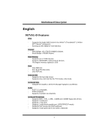
English M7VIG-D Features CPU: - Supports the single AMD Socket A for AthlonTM (ThunderbirdTM )/ Athlon XPTM/ DuronTM processors. - Running at 200/ 266MHz Front Side Bus. Chipset: - North Bridge: VIA VT8375 (KM266) Chipset. - South Bridge: VT8235 Chipset. Main Memory - Supports up - Biostar M7VIG D | M7VIG-D user's manual - Page 4
the highest performance for Windows 98, Windows NT, Windows 2000, Windows Me, Windows XP, LINUX and SCO UNIX. Dimensions - Micro ATX Form Factor: 22.9cm X 21.3cm (W X L) Package contents - HDD Cable X 1, FDD Cable X 1, Fully Setup Driver CD X 1 - Flash Memory Writer for BIOS update X 1 - USB Cable - Biostar M7VIG D | M7VIG-D user's manual - Page 5
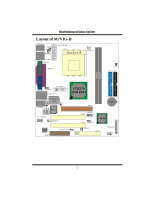
DDeessccrriippttiioonn Layout of M7VIG-D JKBMS1 JKBV1 1 1 JATXPWER1 JUSBV2 1 J C FA N 1 JUSB4 JCOM1 JPRNT1 IDE1 IDE2 DDR1 DDR2 PRIMARY IDE CONN. SECONDARY IDE CONN. JGAME1 1 JVGA1 JUSBV1 2 1 16 15 JUSBLAN1 VT8375 (KM 266) Winbond I/O 1 JAUDIO 1 LAN Phy BIOS 2 10 1 19 BAT1 - Biostar M7VIG D | M7VIG-D user's manual - Page 6
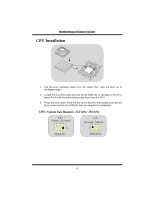
Pin A in the socket and lock for the white dot or cut edge in the CPU. Match Pin A with the white dot/cut edge then insert the CPU. 3. Press the lever down. Then Put the fan on the CPU and buckle it and put the fan's power port into the JCFAN1, then to - Biostar M7VIG D | M7VIG-D user's manual - Page 7
Unbuffered DDR 200/266MHz (without ECC) Type required. DRAM Type: 64MB/ 128MB/ 256MB/ 512MB/ 1GB DIMM Module (184 pin) DIMM Socket Location DDR Module Total Memory Size (MB) DDR 1 64MB/128MB/256MB/512MB/1GB *1 Max is DDR 2 64MB/128MB/256MB/512MB/1GB *1 2GB * The list shown above for DRAM - Biostar M7VIG D | M7VIG-D user's manual - Page 8
Disk Connector: FDD1 The motherboard provides a standard floppy disk connector that supports 360K, 720K, 1.2M, 1.44M and 2.88M floppy disk types. This connector supports the provided floppy drive ribbon cables. Audio Modem Riser Slot: AMR1 (Only support slave card) The AMR specification is an open - Biostar M7VIG D | M7VIG-D user's manual - Page 9
MMootthheerrbbooaarrdd DDeessccrriippttiioonn Wake On LAN Header: JWOL1 Ground 5V_SB Wake up 1 JWOL1 Clear CMOS Jumper: JCMOS1 JCMOS1 Assignment 1 Pin 1-2 on Normal Operation (default) 1 Clear CMOS Pin 2-3 on Data Front USB Header: JUSB3 2 1 JUSB3 Pin Assignment Pin Assignment 1 +5V 2 +5V - Biostar M7VIG D | M7VIG-D user's manual - Page 10
MMootthheerrbbooaarrdd DDeessccrriippttiioonn 5V/ 5VSB Selection for USB: JUSBV1/2/3 JUSBV1/2/3 Assignment 1 5V Pin 1-2 on 1 5V_SB Pin 2-3 on CPU Frequency Selection: JCLK1 1 Close ==> 100 MHz JCLK1 Open ==> 133 Mhz 5V/ 5VSB Selection for Keyboard: JKBV1 JKBV1 Assignment 1 5V Pin 1-2 on 1 - Biostar M7VIG D | M7VIG-D user's manual - Page 11
Case Open Pin 1-2 on Front Panel Connector: JPANEL1 PWR_LED SLP ON/OFF IR 2 24 1 23 SPK (+) (-) RST IR HLED SPK ==> Speaker Conn. HLED ==> Hard Driver LED RST ==> Reset Button IR ==> Infrared Conn. SLP ==> Sleep Button PWR_LED ==> Power LED ON/ OFF ==> Power-on Button Digital - Biostar M7VIG D | M7VIG-D user's manual - Page 12
Assignment 1 Mic In 3 Mic Power 5 RT Line Out 7 Reserved 9 LFT Line Out JF_AUDIO Pin Assignment 2 Ground 4 Audio Power 6 RT Line Out 8 Key 10 LFT Line Out Front Panel Audio Connector/ Jumper Block Jumper Setting 12 3 5 7 46 Pin 5 and 6 Pin 9 and 10 9 10 1 3 5 462 No - Biostar M7VIG D | M7VIG-D user's manual - Page 13
MMootthheerrbbooaarrdd DDeessccrriippttiioonn Game Header: JGAME1 2 1 16 15 JGAME1 Pin Assignment Pin Assignment 1 +5V 2 +5V 3 GP6 4 GP4 5 GP2 6 GP0 7 MIDI-OUTR 8 Ground 9 GP3 10 Ground 11 GP7 12 GP1 13 MIDI-INR 14 GP5 15 NC 16 +5V Back Panel Connectors JKBMS1 PS/2 Mouse JUSB4 PS/2 - Biostar M7VIG D | M7VIG-D user's manual - Page 14
M7VIG-D CPU: - Soporta procesadores single AMD Socket A para AthlonTM (ThunderbirdTM )/ Athlon XPTM/ DuronTM. - Corre a 200/ 266MHz Front Side Bus. Chipset: - North Bridge: VIA VT8375 (KM266) Chipset. - South Bridge: VT8235 Chipset gráfico. Audio - AC97 BIOS - AWARD legal Bios. - Soporta APM1.2. 12 - Biostar M7VIG D | M7VIG-D user's manual - Page 15
para Windows 98, Windows NT, Windows 2000, Windows Me, Windows XP, LINUX y SCO UNIX. Dimensiones - Factor de Forma Micro ATX: 22.9cm X 21.3cm (W X L) Contenido del Paquete - Cable HDD X 1 - Cable FDD X 1 - Completa Configuración del Driver CD X 1 - Flash Memory Writer para actualización del BIOS - Biostar M7VIG D | M7VIG-D user's manual - Page 16
MMootthheerrbbooaarrdd DDeessccrriippttiioonn Disposición del M7VIG-D JKBMS1 JKBV1 11 JATXPWER1 JUSBV2 1 JCFAN1 JUSB4 JCOM1 JPRNT1 IDE1 IDE2 DDR1 DDR2 JGAME1 1 JVGA1 JUSBV1 2 1 16 15 JUSBLAN1 VT8375 (KM 266) Winbond I/O 1 JAUDIO 1 LAN Phy BIOS 2 10 1 19 BAT1 JUSB3 PCI1 2 - Biostar M7VIG D | M7VIG-D user's manual - Page 17
contacto A del zócalo y busque el punto blanco o corte el borde en la CPU. Empareje el contacto A con el punto blanco/ corte del borde, luego inserte la CPU. 3. Presione la palanca para abajo. Ponga el ventilador en la CPU y abróchelo. Luego ponga el puerto de corriente del ventilador en el JCFAN1 - Biostar M7VIG D | M7VIG-D user's manual - Page 18
MMootthheerrbbooaarrdd DDeessccrriippttiioonn Módulos DDR DIMM: DDR1-2 DRAM Tiempo de Acceso: 2.5V Unbuffered DDR 200/ 266 MHz (sin ECC) Tipo requerido. DRAM Tipo: 64MB/ 128MB/ 256MB/ 512MB/ 1GB Módulo DIMM (184 pin) Localización del Módulo DIMM Módulo DDR Total del Tamaño de Memoria (MB) DDR 1 - Biostar M7VIG D | M7VIG-D user's manual - Page 19
una tarjeta elevadora de interface del hardware en el que soporta solamente audio y módem. Ranura de Interconexión del Componente Periférico: PCI1-2 Su monitor se fijará directamente a la tarjeta de video. Ésta placa madre soporta tarjetas de video para PCI, pero también está equipada con puerto - Biostar M7VIG D | M7VIG-D user's manual - Page 20
MMootthheerrbbooaarrdd DDeessccrriippttiioonn Cabezal Wake On LAN: JWOL1 Tierra 5V_SB Wake up 1 JWOL1 Puente de Borrar CMOS: JCMOS1 JCMOS1 Asignacion 1 Contacto 1-2 on Operacion Normal (Default) 1 Borrar Datos Contacto CMOS 2-3 on Cabezal Frontal USB: JUSB3 2 1 JUSB3 Contactos Asignacion - Biostar M7VIG D | M7VIG-D user's manual - Page 21
5V/ 5VSB Selección para USB: JUSBV1/2/3 JUSBV1/ 2/ 3 Asignacion 1 Contactos 5V 1-2 on 1 Contactos 2-3 on 5V_SB Selección de Frecuencia del CPU: JCLK1 1 Cerrado ==> 100 MHz JCLK1 Abierto ==> 133 Mhz 5V/ 5VSB Selección para Teclado: JKBV1 JKBV1 1 Contactos 1-2 on Asignacion 5V - Biostar M7VIG D | M7VIG-D user's manual - Page 22
MMootthheerrbbooaarrdd DDeessccrriippttiioonn AMR Codec de Selección Primario/ Secundario: JCODECSEL JCODECSEL Contacto 1 1-2 Contacto 1 2-3 Asignacion Codec Primario Onboard (Default) AMR Codec Primario. Conector Case Open: JCI1 JCI1 Asignacion 1 Operacion Puente sin instalar Normal - Biostar M7VIG D | M7VIG-D user's manual - Page 23
: JSPDIF1 (Optional) SPDIF_OUT 5V GND 1 JSPDIF1 Subsistema de Audio: JF_AUDIO1/ JCDIN1 2 1 1 JF_AUDIO1 JCDIN1 (Cabezal de Audio Frontal) (Cabezal de Entrada de Audio CD-ROM) 22 1 10 9 JF_AUDIO Contactos 1 3 5 7 9 Asignacion Entrada del MIC Corriente del MIC RT Salida de Linea Reservado - Biostar M7VIG D | M7VIG-D user's manual - Page 24
trasero. 9 10 1 3 5 7 246 No jumpers installed 9 10 La se~nal de salida de linea del Audio y la se~nal del entrada del mic estan disponibles desde el conector de Audio del panel frontal. Cabezal de Juego: JGAME1 2 1 16 15 JGAME1 Contactos Asignacion Contactos Asignacion 1 +5V 2 +5V - Biostar M7VIG D | M7VIG-D user's manual - Page 25
M7VIG-D CPU: - Unterstützt Athlon™ (Thunderbird™) / Athlon XP™ -VGA - Mit integriertem 128-Bit S3 ProSavage 8 Grafikken. Audio - AC97 2.2 kompatible. - Entspricht den Anfordungen von PC 99P Ports. (optional, hinten*2/vorn*4) BIOS - Unterstützung für AWARD legal Bios. - Unterstützung für APM1.2.. 23 - Biostar M7VIG D | M7VIG-D user's manual - Page 26
Betriebsysteme wie Window 98, Windows NT, Windows 2000, Windows ME, Windows XP, LINUX and SCO UNIX Abmessungen - Micro ATX Form-Factor:: 22.9cm X 21.3cm (W X L) Verpackungsinhalt - HDD Kable X 1 - FDD Kable X 1 - Treiber CD für InstallationX 1 - Flash-Speicher-Writer für BIOS-Update X 1 - USB Kable - Biostar M7VIG D | M7VIG-D user's manual - Page 27
DDeessccrriippttiioonn Layout des M7VIG-D JKBMS1 JKBV1 1 1 JUSBV2 JUSB4 JCOM1 JATXPWER1 1 JCFAN1 JPRNT1 IDE1 IDE2 DDR1 DDR2 PRIMARY IDE CONN. SECONDARY IDE CONN. JGAME1 1 2 16 JVGA1 JUSBV1 1 15 JUSBLAN1 VT8375 (KM 266) Winbond I/O 1 JAUDIO 1 LAN Phy BIOS 2 10 1 19 BAT1 - Biostar M7VIG D | M7VIG-D user's manual - Page 28
90-Grad nach oben. 2. Suchen Sie Pin A im Sockel und den weißen Punkt oder die Abschnittkante in der CPU. Passen Sie Pin A mit dem weißen Punkt/der Abschnittkante zusammen und legen Sie danach die CPU ein. 3. Drücken Sie den Hebel nach unten. Befestigen Sie danach den Lüfter auf die - Biostar M7VIG D | M7VIG-D user's manual - Page 29
MMootthheerrbbooaarrdd DDeessccrriippttiioonn DDR-DIMM-Modules: DDR1-2 DRAM Zugriffszeit: 2.5V unbuffered DDR 200/266MHz (ohne ECC) Typen required. DRAM Typen: 64MB/ 128MB/ 256MB/ 512MB/ 1GB DIMM-Module (184-Pin) DIMM-Sockel Standort DDR-Module Speichergröße (MB) DDR 1 64MB/128MB/256MB/512MB/ - Biostar M7VIG D | M7VIG-D user's manual - Page 30
unterstützt. Dieser Anschluss unterstützt die mitgelieferte Bandkabel des Diskettenlaufwerks. Audio Modem Riser: AMR1 (untertützt nur Slave-Karte) Die AMR- AGP1 Ihr Monitor wird direkt an die Grafikkarte angeschlossen. Dieses Motherboard unterstützt Grafikkarten für PCI-Slots, aber es ist auch - Biostar M7VIG D | M7VIG-D user's manual - Page 31
MMootthheerrbbooaarrdd DDeessccrriippttiioonn Wake On LAN Header: JWOL1 Grund 5V_SB Erwachen 1 JWOL1 Clear CMOS Jumper: JCMOS1 JCMOS1 1 Pin 1-2 geschlossen 1 Pin 2-3 geschlossen Beschreibung Normale Operation (Default) CMOS-Daten loschen Front USB Header: JUSB3 2 1 JUSB3 Pin Beschreibung Pin - Biostar M7VIG D | M7VIG-D user's manual - Page 32
MMootthheerrbbooaarrdd DDeessccrriippttiioonn 5V/ 5V_SB Auswahl für USB: JUSBV1/2/3 JUSBV1/2/3 Beschreibung 1 Pin 1-2 5V geschlossen 1 Pin 2-3 geschlossen 5V_SB CPU Frequenz Auswahl: JCLK1 1 geschlossen ==> 100 MHz JCLK1 geoffnet ==> 133 Mhz 5V/ 5VSB Auswahl für Tastatur: JKBV1 JKBV1 - Biostar M7VIG D | M7VIG-D user's manual - Page 33
MMootthheerrbbooaarrdd DDeessccrriippttiioonn Auswahl für Primär/ Sekundär AMR Codec: JCODECSEL J_CODECSEL Pin1-2 1 geschlossen Pin 2-3 1 geschlossen Beschreibung Primar Onboard Codec(Default) Primar AMRCodec Anschluss für Gehäuse-Öffnen: JCI1: JCI1 JCI1 1 Kein Jumper geschlossen Normale - Biostar M7VIG D | M7VIG-D user's manual - Page 34
: JSPDIF1 (optional) SPDIF_OUT 5V Grund 1 JSPDIF1 Audio Subsystem: JF_AUDIO/ JCDIN1 2121 1 1 ((FFrroonnJttJFAAA_UAuuddDUiiIooDOHHI1Oeeaaddeerr)) ((CCDD-- -Out 7 Reserviert 9 LFT Lin-Out JF_AUDIO1 Pin Beschreibung 2 Grund 4 Audio Power 6 RT Line-Out 8 Key 10 LFT Line-Out 32 - Biostar M7VIG D | M7VIG-D user's manual - Page 35
sse f r die Vorderseite/Jumper-Block Jumper-Einstellen 1 2 3 5 4 6 Pin 5 und 6 Pin 9 und 10 7 9 10 Konfiguration Audio-Ausgang-Singals werden zu der Audio- Ausgang-Anschluss an der Ruckwand geleitet. 1 2 3 5 7 9 4 6 Audio-Ausgang- und Mic-In-Singals sind verfugbar Kein Jumper fur - Biostar M7VIG D | M7VIG-D user's manual - Page 36
MMootthheerrbbooaarrdd DDeessccrriippttiioonn Anschlüsse auf der Rückseite JKBMS1 PS/2Maus JUSB4 PS/2- USB Tastatur JPRNT1 Parallel JUSBLAN1 LAN Line-In LautsprecherAusgang Mic-In COM1 JCOM1 VGA1 JVGA1 USB JAUDIO 34 - Biostar M7VIG D | M7VIG-D user's manual - Page 37
descriptions about BIOS model and chipsets. In addition, the frequency status of CPU, memory, AGP and PCI along with the CPU speed Support: Windows 98 SE, Windows Me, Windows 2000, Windows XP DirectX: DirectX 8.1 or above. (The Windows XP operating system includes DirectX 8.1. If you use Windows XP - Biostar M7VIG D | M7VIG-D user's manual - Page 38
MMootthheerrbbooaarrdd DDeessccrriippttiioonn Installation 1. Execute the setup execution file, and then the following dialog will pop up. Please click "Next" button and follow the default procedure to install. 2. When you see the following dialog in setup procedure, it means setup is completed. If - Biostar M7VIG D | M7VIG-D user's manual - Page 39
MMootthheerrbbooaarrdd DDeessccrriippttiioonn Usage The following figures are just only for reference, the screen printed in this user manual will change according to your motherboard on hand. [WarpSpeeder™] includes 1 tray icon and 5 panels: 1. Tray Icon: Whenever the Tray Icon utility is launched, - Biostar M7VIG D | M7VIG-D user's manual - Page 40
utility will be invoked. Please refer to the following figure; the utility's first window you will see is Main Panel. Main Panel contains features as follows: a. Display the CPU Speed, CPU external clock, Memory clock, AGP clock, and PCI clock information. b. Contains About, Voltage, Overclock, and - Biostar M7VIG D | M7VIG-D user's manual - Page 41
will be highlighted and the Voltage Panel will slide out to up as the following figure. In this panel, you can decide to increase CPU core voltage and Memory voltage or not. The default setting is "No". If you want to get the best performance of overclocking, we recommend you click the - Biostar M7VIG D | M7VIG-D user's manual - Page 42
MMootthheerrbbooaarrdd DDeessccrriippttiioonn 4. Overclock Panel Click the Overclock button in Main Panel, the button will be highlighted and the Overclock Panel will slide out to left as the following figure. 40 - Biostar M7VIG D | M7VIG-D user's manual - Page 43
3MHz button", "-1MHz button", "+1MHz button", and "+3MHz button": provide user the ability to do real-time overclock adjustment. Warning: Manually overclock is potentially dangerous, especially when the overclocking percentage is over 110 %. We strongly recommend you verify every speed you overclock - Biostar M7VIG D | M7VIG-D user's manual - Page 44
MMootthheerrbbooaarrdd DDeessccrriippttiioonn d. "Auto-overclock button": User can click this button and [ WarpSpeeder™ ] will set the best and stable performance and frequency automatically. [ WarpSpeeder™ ] utility will execute a series of testing until system fail. Then system will do fail- - Biostar M7VIG D | M7VIG-D user's manual - Page 45
will slide out to up as the following figure. In this panel, you can get model name and detail information in hints of all the chipset that are related to overclocking. You can also get the mainboard's BIOS model and the Version number of [ WarpSpeeder™ ] utility. 43 - Biostar M7VIG D | M7VIG-D user's manual - Page 46
DDeessccrriippttiioonn Note: Because the overclock, overvoltage, and hardware monitor features are controlled by several separate chipset, [ WarpSpeeder™ ] divide these features to separate panels. If one chipset is not on board, the correlative button in Main panel will be disabled, but will not - Biostar M7VIG D | M7VIG-D user's manual - Page 47
Trouble Shooting PROBABLE SOLUTION No power to the system at all Power light don't * Make sure power cable is securely plugged in illuminate, fan inside power supply does not on. Indicator light on keyboard does not turn turn on * Replace cable * Contact technical support PROBABLE - Biostar M7VIG D | M7VIG-D user's manual - Page 48
Solución de Problemas CAUSA PROBABLE SOLUCIÓN No hay corriente en el sistema. La luz de * Asegúrese que el cable de transmisión esté corriente no ilumina, ventilador dentro de la seguramente enchufado. fuente de alimentación apagada. luz del teclado apagado. Indicador de * Reemplace el cable - Biostar M7VIG D | M7VIG-D user's manual - Page 49
Problemlösung MÖGLICHE URSACHE LÖSUNG Das System hat keine Spannungsversorgung. * Versichern Sie sich, dass das Stromkabel richtig Die Stromanzeige leuchtet nicht, der Lüfter im angebracht ist Inneren der eingeschaltet. Stromversorgung Tastaturleuchten sind wird nicht nicht an. * Ersetzen - Biostar M7VIG D | M7VIG-D user's manual - Page 50
03/14/2003 48
-
 1
1 -
 2
2 -
 3
3 -
 4
4 -
 5
5 -
 6
6 -
 7
7 -
8
-
9
-
10
-
11
-
12
-
13
-
14
-
15
-
16
-
17
-
18
-
19
-
20
-
21
-
22
-
23
-
24
-
25
-
26
-
27
-
28
-
29
-
30
-
31
-
32
-
33
-
34
-
35
-
36
-
37
-
38
-
39
-
40
-
41
-
42
-
43
-
44
-
45
-
46
-
47
-
48
-
49
-
50
 |
 |

M
M
7
7
V
V
I
I
G
G
-
-
D
D
i
FCC Statement and Copyright
This equipment has been tested and found to comply with the limits of a Class B
digital device, pursuant to Part 15 of the FCC Rules. These limits are designed to
provide reasonable protection against harmful interference in a residential
installation. This equipment generates, uses and can radiate radio frequency
energy and, if not installed and used in accordance with the instructions, may
cause harmful interference to radio communications. There is no guarantee that
interference will not occur in a particular installation.
The vendor makes no representations or warranties with respect to the contents
here of and specially disclaims any implied warranties of merchantability or
fitness for any purpose. Further the vendor reserves the right to revise this
publication and to make changes to the contents here of without obligation to
notify any party beforehand.
Duplication of this publication, in part or in whole is not allowed without first
obtaining the vendor’s approval in writing.
The content of this user’s is subject to be changed without notice and we will not
be responsible for any mistakes found in this user’s manual. All the brand and
product names are trademarks of their respective companies.