Biostar M7VIT BRAVO M7VIT Bravo user's manual
Biostar M7VIT BRAVO Manual
 |
View all Biostar M7VIT BRAVO manuals
Add to My Manuals
Save this manual to your list of manuals |
Biostar M7VIT BRAVO manual content summary:
- Biostar M7VIT BRAVO | M7VIT Bravo user's manual - Page 1
energy and, if not installed and used in accordance with the instructions, may cause harmful interference to radio communications. There is no guarantee the vendor's approval in writing. The content of this user's manual is subject to be changed without notice and we will not be responsible for any - Biostar M7VIT BRAVO | M7VIT Bravo user's manual - Page 2
4 M7VIT Bravo Features 4 Package contents...5 How to set up Jumper 6 CPU Installation...6 DDR DIMM Modules: DDR1, DDR2 7 Installing DDR Module 7 Jumpers, Headers, Connectors & Slots 8 WARPSPEEDER 13 Introduction ...13 System Requirement 13 Installation ...14 Usage ...15 TROUBLE SHOOTING - Biostar M7VIT BRAVO | M7VIT Bravo user's manual - Page 3
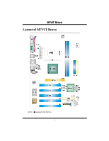
MM77VVIITT BBrraavvoo Layout of M7VIT Bravo NOTE: ●represents the first pin. 1 - Biostar M7VIT BRAVO | M7VIT Bravo user's manual - Page 4
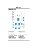
E. Front Audio Header:JAUDIO1 N. Front USB Header:JUSB2/(JUSB3)* F. Accelerated Graphics Port Slot:AGP1 O. IDE Connectors:IDE1-2 G. PCI BUS Slots:PCI 1-5 P. DDR Modules:DDR1-2 H. Front Panel Connector:JPANEL1 Q. Frequency Selection:JCLK1 I. Clear CMOS Function:JCMOS1 R. CPU Fan Connector - Biostar M7VIT BRAVO | M7VIT Bravo user's manual - Page 5
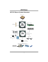
MM77VVIITT BBrraavvoo M7VIT Bravo System Structure CPU+SocketA AGP4X/8X KT400A DDR266/333/400 6 USB2.0 VT8235CE AC?7 VIA VT 6103 BIOS 10Mb/s, 100Mb/s LAN 5 PCI Master ATA33/66/100/133 IDE1/IDE2 ITE I/O ITE IT8705F Floopy/Printer/Keyboard/Mouse 3 - Biostar M7VIT BRAVO | M7VIT Bravo user's manual - Page 6
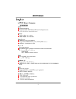
MM77VVIITT BBrraavvoo English M7VIT Bravo Features A. Hardware CPU Provides Socket A. Supports single AMD® Athlon XP/ Duron Family processor. Front Side Bus at 200/266/333 MHz. Chipset North Bridge: VIA KT400A. South Bridge: VIA VT8235CE. Main Memory Supports up to 2 DDR devices. Supports 266/333/ - Biostar M7VIT BRAVO | M7VIT Bravo user's manual - Page 7
. Supports APM1.2. Supports ACPI. Supports USB Function. Software Supports Warpspeeder™, 9th Touch™, FLASHER™. Offers the highest performance for Windows 98 SE, Windows 2000, Windows Me, Windows XP, UNIX Series etc. Package contents HDD Cable X 1 FDD Cable X 1 User's Manual X 1 Fully Setup Driver CD - Biostar M7VIT BRAVO | M7VIT Bravo user's manual - Page 8
jumper whose pin 1 and 2 are "close" when jumper cap is placed on these 2 pins. Jumper open Jumper close Pin1-2 close CPU Installation Step1: Pull the lever sideways away from the socket and then raise the lever up to a 90-degree angle. Step2: Look for the white dot/cut edge. The white dot - Biostar M7VIT BRAVO | M7VIT Bravo user's manual - Page 9
MM77VVIITT BBrraavvoo CPU Fan Header: JCFAN1 1 Pin 1 JCFAN1 2 3 Assignment Ground +12V FAN RPM rate DRAM Type: 64MB/ 128MB/ 256MB/ 512MB/ 1GB DIMM Module (184 pin) DIMM Socket Location DDR Module Total Memory Size (MB) DDR 1 64MB/128MB/256MB/512MB/1GB *1 Max is DDR 2 64MB/128MB/256MB/ - Biostar M7VIT BRAVO | M7VIT Bravo user's manual - Page 10
that video card. This motherboard supports video cards for PCI spec and can transfer data with 1.5 Gb/s speed. 65 3 2 Pin Assignment Pin 1 Ground 2 Assignment TX+ 3 TX- 4 741 5 RX- 6 JSATA1/ JSATA2 7 Ground Ground RX+ Note: 1. When plugging SATA HDD on JSATA1 connector, SATA BIOS - Biostar M7VIT BRAVO | M7VIT Bravo user's manual - Page 11
MM77VVIITT BBrraavvoo Front Panel Connector: JPANEL1 JPANEL1 SLP PWR_LED (+) (+)(-) ON/OFF 2 1 SPK (+) (-) HLED RST IR 24 23 IR Pin Assignment 1 +5V 3 NA 5 NA 7 Speaker 9 HDD LED (+) 11 HDD LED (-) 13 Ground 15 Reset Control 17 NA 19 NA 21 +5V 23 IRTX Function - Biostar M7VIT BRAVO | M7VIT Bravo user's manual - Page 12
on the AC. 6. Reset your desired password or clear the CMOS data. Case Open Connector: JCI1 1 Pin 1 JCI1 2 Assignment Case Open Signal Ground CD-ROM Audio-In Header: JCDIN1 Pin Assignment 1 JCDIN1 1 Left Channel Input 2 Ground 3 Ground 4 Right Channel Input Digital - Biostar M7VIT BRAVO | M7VIT Bravo user's manual - Page 13
Header: JAUDIO1 2 14 1 13 JAUDIO1 Pin Assignment Pin Assignment 1 Left stereo Mic In/ Center 2 Ground 3 Right stereo Mic In/ Bass 4 Audio Power 5 Right Line Out/ Speaker Out 6 Right Line Out/ Speaker Out Right Right 7 Reserved 8 Key 9 Left Line Out/ Speaker Out 10 Left Line - Biostar M7VIT BRAVO | M7VIT Bravo user's manual - Page 14
MM77VVIITT BBrraavvoo Back Panel Connectors LAN Printer Port PS/2 PS/2 COM1 USB USB Keyboard Mouse (Optional) Line In Speaker Out Mic In 6 Channel Speakers Speaker Out/ Right & Left Line In/ Rear Speaker (Left & Right) Mic In/ Center & Bass 12 - Biostar M7VIT BRAVO | M7VIT Bravo user's manual - Page 15
, in the About panel, you can get detail descriptions about BIOS model and chipsets. In addition, the frequency status of CPU, memory, AGP and PCI along with the CPU speed are synchronically shown on our main panel. Moreover, to protect users' computer systems if the setting is not appropriate when - Biostar M7VIT BRAVO | M7VIT Bravo user's manual - Page 16
MM77VVIITT BBrraavvoo Installation 1. Execute the setup execution file, and then the following dialog will pop up. Please click "Next" button and follow the default procedure to install. 2. When you see the following dialog in setup procedure, it means setup is completed. If the "Launch the - Biostar M7VIT BRAVO | M7VIT Bravo user's manual - Page 17
MM77VVIITT BBrraavvoo Usage The following figures are just only for reference, the screen printed in this user manual will change according to your motherboard on hand. [WarpSpeeder™] includes 1 tray icon and 5 panels: 1. Tray Icon: Whenever the Tray Icon utility is launched, it will display a - Biostar M7VIT BRAVO | M7VIT Bravo user's manual - Page 18
[ WarpSpeeder™ ] utility will be invoked. Please refer do the following figure; the utility's first window you will see is Main Panel. Main Panel contains features as follows: a. Display the CPU Speed, CPU external clock, Memory clock, AGP clock, and PCI clock information. b. Contains About, Voltage - Biostar M7VIT BRAVO | M7VIT Bravo user's manual - Page 19
button will be highlighted and the Voltage Panel will slide out to up as the following figure. In this panel, you can decide to increase CPU core voltage and Memory voltage or not. The default setting is "No". If you want to get the best performance of overclocking, we recommend you - Biostar M7VIT BRAVO | M7VIT Bravo user's manual - Page 20
MM77VVIITT BBrraavvoo 4. Overclock Panel Click the Overclock button in Main Panel, the button will be highlighted and the Overclock Panel will slide out to left as the following figure. 18 - Biostar M7VIT BRAVO | M7VIT Bravo user's manual - Page 21
contains the these features: a. "-3MHz button", "-1MHz button", "+1MHz button", and "+3MHz button": provide user the ability to do real-time overclock adjustment. Warning: Manually overclock is potentially dangerous, especially when the overclocking percentage is over 110 %. We strongly recommend - Biostar M7VIT BRAVO | M7VIT Bravo user's manual - Page 22
restore to the hardware default setting or load the verified best and stable frequency according to the Recovery Dialog's setting. e. "Verify button": User can click this button and [ WarpSpeeder™ ] will proceed a testing for current frequency. If the testing is ok, then the current frequency will - Biostar M7VIT BRAVO | M7VIT Bravo user's manual - Page 23
, you can get model name and detail information in hints of all the chipset that are related to overclocking. You can also get the mainboard's BIOS model and the Version number of [ WarpSpeeder™ ] utility. 21 - Biostar M7VIT BRAVO | M7VIT Bravo user's manual - Page 24
MM77VVIITT BBrraavvoo Note: Because the overclock, overvoltage, and hardware monitor features are controlled by several separate chipset, [ WarpSpeeder™ ] divide these features to separate panels. If one chipset is not on board, the correlative button in Main panel will be disabled, but will not - Biostar M7VIT BRAVO | M7VIT Bravo user's manual - Page 25
Trouble Shooting PROBABLE SOLUTION No power to the system at all Power light don't * Make sure power cable is securely plugged in illuminate, fan inside power supply does not turn on. Indicator light on keyboard does not turn on * Replace cable * Contact technical support or * Review system's - Biostar M7VIT BRAVO | M7VIT Bravo user's manual - Page 26
MM77VVIITT BBrraavvoo 12/26/2003 24
-
 1
1 -
 2
2 -
 3
3 -
 4
4 -
 5
5 -
 6
6 -
 7
7 -
8
-
9
-
10
-
11
-
12
-
13
-
14
-
15
-
16
-
17
-
18
-
19
-
20
-
21
-
22
-
23
-
24
-
25
-
26
 |
 |

M
M7
7V
VI
IT
T
B
Br
ra
av
vo
o
i
FCC Information and Copyright
This equipment has been tested and found to comply with the limits of a
Class B digital device, pursuant to Part 15 of the FCC Rules. These limits
are designed to provide reasonable protection against harmful
interference in a residential installation. This equipment generates, uses
and can radiate radio frequency energy and, if not installed and used in
accordance with the instructions, may cause harmful interference to radio
communications. There is no guarantee that interference will not occur in
a particular installation.
The vendor makes no representations or warranties with respect to the
contents here of and specially disclaims any implied
warranties
of
merchantability or fitness for any purpose. Further the vendor reserves
the right to revise this publication and to make changes to the contents
here of without obligation to notify any party beforehand.
Duplication of this publication, in part or in whole, is not allowed without
first obtaining the vendor’s approval in writing.
The content of this user’s manual is subject to be changed without notice
and we will not be responsible for any mistakes found in this user’s
manual. All the brand and product names are trademarks of their
respective companies.