Biostar M7VIW D M7VIW-D user's manual
Biostar M7VIW D Manual
 |
View all Biostar M7VIW D manuals
Add to My Manuals
Save this manual to your list of manuals |
Biostar M7VIW D manual content summary:
- Biostar M7VIW D | M7VIW-D user's manual - Page 1
M7VIW-D FCC Statement and Copyright This energy and, if not installed and used in accordance with the instructions, may cause harmful interference to radio communications. There is no found in this user's manual. All the brand and product names are trademarks of their respective companies. i - Biostar M7VIW D | M7VIW-D user's manual - Page 2
-D 24 Verpackungsinhalt ...25 Layout des M7VIW-D ...26 Installation der CPU...27 DDR-DIMM-Modules: DDR1-2 28 Jumpers, Headers, Connectors & Slots 29 WARPSPEEDER 35 Introduction...35 System Requirement ...35 Installation...36 Usage...37 TROUBLE SHOOTING 46 SOLUCIÓN DE PROBLEMAS 47 PROBLEMLÖSUNG - Biostar M7VIW D | M7VIW-D user's manual - Page 3
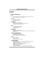
DDeessccrriippttiioonn English M7VIW-D Features CPU - Supports single Socket-A for an AMD® Athlon/ Duron Family processor. - Running at 200/ 266 MHz Front Side Bus. Chipset - North Bridge: VIA KT266A. - South Bridge: VT8235. Main Memory - Supports up to 2 DDR devices. - Supports 200/ 266 - Biostar M7VIW D | M7VIW-D user's manual - Page 4
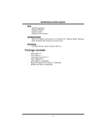
. - Supports USB Function. Operating System - Offers the highest performance for Windows NT, Window 98SE, Windows 2000, Windows Me, Windows XP and LINUX. Dimensions - ATX Form Factor: 20cm X 30.5cm (W X L). Package contents - HDD Cable X 1 - FDD Cable X 1 - Fully Setup Driver CD X 1 - User's Manual - Biostar M7VIW D | M7VIW-D user's manual - Page 5
MMootthheerrbbooaarrdd DDeessccrriippttiioonn Layout of M7VIW-D 1 1 JKBV1 JUSBV1 CPU MIC-IN LINE-IN SP-OUT GAME Port Socket A 1 JATXPWR1 KT266A 1 12 JGAME1 JAUDIO1 13 14 1 1 LAN Chip AGP SLOT PCI1 PCI SLOT IDE1 IDE2 BAT1 Codec 1 ITE I/O PCI SLOT PCI SLOT PCI SLOT PCI2 JUSB2 2 - Biostar M7VIW D | M7VIW-D user's manual - Page 6
MMootthheerrbbooaarrdd DDeessccrriippttiioonn CPU Installation CPU 1. Pull the lever sideways away from the socket then raise the lever up to 90-degree angle. 2. Locate Pin A in the socket and lock for the white dot or cut edge in the CPU. Match Pin A with the white dot/cut edge then insert the - Biostar M7VIW D | M7VIW-D user's manual - Page 7
/256MB/512MB/1GB 2GB *1 The list shown above for DRAM configuration is only for reference. How to install a DIMM Module DDR DIMM Module 1. The DIMM socket has a " Plastic Safety Tab", and the DIMM memory module has an "Asymmetrical notch", so the DIMM memory module can only fit into the slot in - Biostar M7VIW D | M7VIW-D user's manual - Page 8
an open Industry Standard Architecture, and it defines a hardware scalable riser card interface, which supports audio, network and modem only. Peripheral Component Interconnect Slots: PCI1-5 This motherboard is equipped with 5 standard PCI slots. PCI stands for Peripheral Component Interconnect, and - Biostar M7VIW D | M7VIW-D user's manual - Page 9
up Function) Front Panel Connector: JPANEL1 PWR_LED SLP (+) (+) (-) ON/OFF IR 2 24 1 23 (+) (-) SPK RST IR HLED SPK ==> Speaker Conn. HLED ==> Hard Driver LED RST ==> Reset Button IR ==> Infrared Conn. SLP ==> Sleep Button PWR_LED ==> Power LED ON/ OFF ==> Power-on Button 7 - Biostar M7VIW D | M7VIW-D user's manual - Page 10
JCLK1 Pin 1-2 ==> 133 MHz (default) Pin 2-3 ==> 100 Mhz Audio Subsystem: JAUDIO1/ JCDIN1/ JCDIN2 • JAUDIO1 with 14 pins only support Codec 6CH, CMI9739A/ 9760 (Optional) JAUDIO1 (Front Audio Header) 12 1 JCDIN2 (CD-ROM Audio-In Header) 1 JCDIN1 (CD-ROM Audio-In Header) 22 1 14 13 JAUDIO1 Pin - Biostar M7VIW D | M7VIW-D user's manual - Page 11
. 12 3 5 4 6 No jumpers 7 9 10 installed 11 12 13 14 Audio line out and mic in signals are available for front panel audio connectors. • JAUDIO1 with 10 pins only support Codec 2CH, VIA VT1612A (Optional) JAUDIO1 (Front Audio Header) 12 1 JCDIN2 (CD-ROM Audio-In Header) 1 JCDIN1 (CD-ROM - Biostar M7VIW D | M7VIW-D user's manual - Page 12
1 Mic In 3 Mic Power 5 RT Line Out 7 Reserved 9 LFT Line Out JAUDIO1 Pin Assignment 2 Ground 4 Audio Power 6 RT Line Out 8 NC 10 LFT Line Out Front Panel Audio Connector/ Jumper Block Jumper Setting 1 3 5 7 462 Pin 5 and 6 Pin 9 and 10 9 10 12 3 5 4 6 No jumpers - Biostar M7VIW D | M7VIW-D user's manual - Page 13
MMootthheerrbbooaarrdd DDeessccrriippttiioonn Clear CMOS Jumper: JCMOS1 JCMOS1 Assignment 1 Normal Operation Pin 1-2 on (default) 1 Clear CMOS Pin 2-3 on Data Case Open Connector: JCI1 JCI1 1 No jumper installed 1 Pin 1-2 on Assignment Normal Operation (default) Case Open Back Panel - Biostar M7VIW D | M7VIW-D user's manual - Page 14
M7VIW-D CPU - Soporta familia de procesadores single Socket-A para AMD® Athlon/ Duron. - Corriendo a 200/ 266 MHz Front Side Bus. Chipset - North Bridge: VIA KT266A / 10 Mbps. - Auto Negociación: 10/ 100, Full/ Half Duplex. Audio - AC97 2.2 compatible. - PC99 compatible. - Soporta 2 canales de salida - Biostar M7VIW D | M7VIW-D user's manual - Page 15
Window 98SE, Windows 2000, Windows Me, Windows XP y LINUX. Dimensiones - Forma de Factor ATX: 20cm X 30.5cm (W X L). Contenidos del Paquete - Cable HDD X 1 - Cable FDD X 1 - Completa Configuración del Driver CD X 1 - Manual del Usuario X 1 - Cable USB X 2 (Opcional) - Panel Trasero I/O para carcasa - Biostar M7VIW D | M7VIW-D user's manual - Page 16
MMootthheerrbbooaarrdd DDeessccrriippttiioonn Disposición del M7VIW-D 1 1 JKBV1 JUSBV1 CPU Entrada Entrada Salida del del MIC de Linea Altavoz Puerto de Juego Socket A 1 J AT X PW R 1 KT266A 1 12 JGAME1 JAUDIO1 13 14 1 LAN Chip 1 Codec 1 ITE I/O BIOS IDE1 IDE2 PCI1 BAT1 CNR1 - Biostar M7VIW D | M7VIW-D user's manual - Page 17
MMootthheerrbbooaarrdd DDeessccrriippttiioonn Instalación del CPU CPU 1. Tire de la palanca del lado del zócalo, luego levante la palanca hasta un ángulo de 90 grados. 2. Sitúe el contacto A del zócalo y busque el punto blanco o corte el borde en la CPU. Empareje el contacto A con el punto blanco/ - Biostar M7VIW D | M7VIW-D user's manual - Page 18
DDR 200 MHz (PC1600)/ DDR 266 MHz (PC2100) Tipo requerido. DRAM Tipo: 64MB/ 128MB/ 256MB/ 512MB/ 1GB Módulo DIMM (184 contactos) Localización del Socket DIMM Módulo DDR Total del Tamaño de Memoria (MB) DDR 1 64MB/128MB/256MB/512MB/1GB DDR 2 *1 Máxima 2GB 64MB/128MB/256MB/512MB/1GB *1 La - Biostar M7VIW D | M7VIW-D user's manual - Page 19
Industria de Arquitectura Estándar, que define una tarjeta de interface escalable del hardware en el que soporta audio y modem. Ranura de Interconexión del Componente Periférico: PCI1-5 Ésta placa madre está equipada 32 bits. Conector de Corriente: JATXPWR1 JATXPWR1 (Conector de Corriente ATX) 17 - Biostar M7VIW D | M7VIW-D user's manual - Page 20
MMootthheerrbbooaarrdd DDeessccrriippttiioonn Cabezal Wake On LAN: JWOL1 Tierra Wake up 5V_SB 1 WOL1 Cabezal Frontal USB: JUSB2/3 2 1 JUSB2/ 3 Contactos Asignacion 1 +5V 3 Data (-) 5 Data (+) 7 Tierra 9 Key Contactos 2 4 6 8 10 Asignacion +5V Data (-) Data (+) Ground NA 5V/ 5VSB - Biostar M7VIW D | M7VIW-D user's manual - Page 21
MMootthheerrbbooaarrdd DDeessccrriippttiioonn Conector del Panel Frontal: JPANEL1 PWR_LED SLP ON/OFF IR 2 24 1 23 SPK (+) (-) RST IR HLED SPK ==> Conector de Altavoz HLED RST IR ==> LED del Disco Duro ==> Boton de Reinicio ==> Conector Infrarojo SLP ==> Boton de Suspension PWR_LED - Biostar M7VIW D | M7VIW-D user's manual - Page 22
• JAUDIO1 con 14 contactos solamente soporta Codec 6CH, CMI9739A/ 9760 (Opcional) JAUDIO1 1 (Cabezal de Audio Frontal) 12 JCDIN2 (Cabezal de Entrada de Audio CD-ROM) 1 JCDIN1 (Cabezal de Entrada de Audio CD-ROM) 22 1 14 13 JAUDIO1 Pin Assignment Pin Assignment 1 Mic In 2 Ground - Biostar M7VIW D | M7VIW-D user's manual - Page 23
connectors. • JAUDIO1 con 10 contactos solamente soporta Codec 2CH, VIA VT1612A (Opcional) 1 JAUDIO1 (Cabezal de Audio Frontal) JCDIN2 12 (Cabezal de Entrada de Audio CD-ROM) 1 JCDIN1 (Cabezal de Entrada de Audio CD-ROM) 22 1 10 9 JAUDIO1 Contactos 1 3 5 7 9 Asignacion Entrada del - Biostar M7VIW D | M7VIW-D user's manual - Page 24
3 5 7 46 No jumpers installed 9 10 La se~nal de salida de linea del Audio y la se~nal del entrada del mic estan disponibles desde el conector de Audio del panel frontal. Conector de Audio Digital: JSPDIF1 JSPDIF1 1 Pin Assignment 1 VCC5 2 SPDIF_OUT 3 GND Puente de Borrar CMOS: JCMOS1 - Biostar M7VIW D | M7VIW-D user's manual - Page 25
MMootthheerrbbooaarrdd DDeessccrriippttiioonn Conector de la Carcasa Abierta: JCI1 JCI1 Asignacion 1 Puente sin instalar Operacion Normal (default) 1 Carcasa Abierta Contacto 1-2 on Conectores del Panel Trasero JKBMS1 JUSBLAN1 Raton LAN(Opcional) PS/2 JPRNT1 Paralelo JGAME1 Puerto de Juego - Biostar M7VIW D | M7VIW-D user's manual - Page 26
M7VIW-D CPU - Unterstützung für Sockel A für die AMD® Athlon/ Duron-Familie Prozessor. - FSB 200/266 MHz. Chipsatz - Northbridge: VIA KT266A Dual speed-10/ 100 Mbps. - Auto-Negotiation: 10/ 100, Halb/Voll-Duplex. Audio - AC97 2.2 kompatible. - Entspricht den Anfordungen von PC 99. - Unterstützung für - Biostar M7VIW D | M7VIW-D user's manual - Page 27
ME, Windows XP, LINUX and SCO UNIX. Abmessungen - ATX Form-Factor: 20cm X 30.5cm (W X L). Verpackungsinhalt - HDD Kable X 1 - FDD Kable X 1 - Fully Setup Driver CD X 1 - Benutzer Handbuch X 1 - USB Kable X 2 (Optional) - I/O-Rückwand für ATX Gehäuse X 1 (optional) - SPDIF-Ausgang-Kable X1 (optional - Biostar M7VIW D | M7VIW-D user's manual - Page 28
SP-OUT GAME Port Sockel A 1 J AT X PW R 1 KT266A 1 12 JGAME1 JAUDIO1 13 14 1 1 LAN Chip AGP SLOT PCI1 PCI SLOT IDE1 IDE2 BAT1 Codec 1 ITE I/O PCI SLOT PCI SLOT PCI SLOT PCI2 JUSB2 2 10 PCI3 1 9 VT8235 JUSB3 2 10 PCI4 19 1 JUSBV2 1 JCMOS1 JCI1 1 BIOS PCI SLOT CNR1 CNR SLOT PCI5 - Biostar M7VIW D | M7VIW-D user's manual - Page 29
MMootthheerrbbooaarrdd DDeessccrriippttiioonn Installation der CPU CPU 1. Ziehen Sie den Hebel seitwärts von der Sockel und neigen Sie ihn um 90-Grad nach oben. 2. Suchen Sie Pin A im Sockel und den weißen Punkt oder die Abschnittkante in der CPU. Passen Sie Pin A mit dem weißen Punkt/der - Biostar M7VIW D | M7VIW-D user's manual - Page 30
MMootthheerrbbooaarrdd DDeessccrriippttiioonn DDR-DIMM-Modules: DDR1-2 DRAM Zugriffszeit: 2.5V Unbuffered/ Registered DDR 200 MHz (PC1600)/ DDR 266 MHz (PC2100) Typen erfordert. DRAM Typen: 64MB/ 128MB/ 256MB/ 512MB/ 1GB DIMM-Module (184-Pin) DIMM-Sockel Standort DDR-Module Speichergröße (MB)) - Biostar M7VIW D | M7VIW-D user's manual - Page 31
Riser-Card-Schnittstelle, welche nur Audio, Netzwerk und Modem unterstützt. Peripheral Component Interconnect Slots: PCI1-5 Dieses Motherboard ist mit 5 standardmäßigen PCI hat. Dieser PCI-Slot ist für 32 bits vorgesehen. Stromversorgungsanschluss: JATXPWR1 JATXPWR1 (ATX Stromanschluss) 29 - Biostar M7VIW D | M7VIW-D user's manual - Page 32
MMootthheerrbbooaarrdd DDeessccrriippttiioonn Wake On LAN Header: JWOL1 Masse Wake-Up 5V_SB 1 Front USB Header: JUSB2/3 2 1 JUSB2/3 Pin Beschreibung Pin Beschreibung 1 +5V 2 +5V 3 Data (-) 4 Data (-) 5 Data (+) 6 Data (+) 7 Masse 8 Masse 9 Schlussel 10 Kein 5V/ 5VSB Auswahl für USB/KB: - Biostar M7VIW D | M7VIW-D user's manual - Page 33
. HLED ==> Festplattenanzeige RST ==> Reset-Taste IR ==> Infrarotanschl. SLP ==> Sleep-Taste PWR_LED ==> Stromanzeige EIN/AUS ==> EIN /Ausschalttaste Audio Subsystem: JAUDIO1/ JCDIN1/ JCDIN2 • JAUDIO1 mit 14-Pins gilt für den Codec CMI9739A/ 9760 (optional) JAUDIO1 (Front - Biostar M7VIW D | M7VIW-D user's manual - Page 34
an der Vo r d er s e i te . • JAUDIO1 mit 10-Pins gilt für den Codec VIA VT1612A (optional) JAUDIO1 (Front Audio Header) 12 1 JCDIN2 (CD-ROM Audio-In Header) 1 JCDIN1 (CD-ROM Audio-In Header) 22 10 1 9 Pin Beschreibung 1 Mic-In 3 Mic Power 5 RT Line-Out 7 Reserviert 9 LFT - Biostar M7VIW D | M7VIW-D user's manual - Page 35
-Ausgang-Singals werden zu der AudioAusgang-Anschluss an der Ruckwand geleitet. Audio-Ausgang- und Mic-In-Singals sind verfugbar fur Audio-Anschlusse an der Vorderseite. Digital Audio Connector: JSPDIF1 JSPDIF1 1 Pin Beschreibung 1 VCC5 2 SPDIF_OUT 3 Masse Jumper zum CMOS-Löschen : JCMOS1 - Biostar M7VIW D | M7VIW-D user's manual - Page 36
MMootthheerrbbooaarrdd DDeessccrriippttiioonn Anschluss für Gehäuse-Öffnen: JCI1 JCI1 Beschreibung 1 Kein Jumper Normale Operation installieren (Default) 1 Pin 1-2 Gehause offnen geschlossen Anschlüsse auf der Rückseite JKBMS1 JUSBLAN1 PS/2- LAN(optional) Maus JPRNT1 Parallel JGAME1 Game - Biostar M7VIW D | M7VIW-D user's manual - Page 37
information. Also, in the About panel, you can get detail descriptions about BIOS model and chipsets. In addition, the frequency status of CPU, memory, AGP either the original system speed or a suitable one. System Requirement OS Support: Windows 98 SE, Windows Me, Windows 2000, Windows XP DirectX: - Biostar M7VIW D | M7VIW-D user's manual - Page 38
MMootthheerrbbooaarrdd DDeessccrriippttiioonn Installation 1. Execute the setup execution file, and then the following dialog will pop up. Please click "Next" button and follow the default procedure to install. 2. When you see the following dialog in setup procedure, it means setup is completed. If - Biostar M7VIW D | M7VIW-D user's manual - Page 39
MMootthheerrbbooaarrdd DDeessccrriippttiioonn Usage The following figures are just only for reference, the screen printed in this user manual will change according to your motherboard on hand. [WarpSpeeder™] includes 1 tray icon and 5 panels: 1. Tray Icon: Whenever the Tray Icon utility is launched, - Biostar M7VIW D | M7VIW-D user's manual - Page 40
MMootthheerrbbooaarrdd DDeessccrriippttiioonn This utility is responsible for conveniently invoking [WarpSpeeder™] Utility. You can use the mouse by clicking the left button in order to invoke [WarpSpeeder™] directly from the little tray icon or you can right-click the little tray icon to pop up a - Biostar M7VIW D | M7VIW-D user's manual - Page 41
MMootthheerrbbooaarrdd DDeessccrriippttiioonn 3. Voltage Panel Click the Voltage button in Main Panel, the button will be highlighted and the Voltage Panel will slide out to up as the following figure. In this panel, you can decide to increase CPU core voltage and Memory voltage or not. The default - Biostar M7VIW D | M7VIW-D user's manual - Page 42
MMootthheerrbbooaarrdd DDeessccrriippttiioonn 40 - Biostar M7VIW D | M7VIW-D user's manual - Page 43
3MHz button", "-1MHz button", "+1MHz button", and "+3MHz button": provide user the ability to do real-time overclock adjustment. Warning: Manually overclock is potentially dangerous, especially when the overclocking percentage is over 110 %. We strongly recommend you verify every speed you overclock - Biostar M7VIW D | M7VIW-D user's manual - Page 44
MMootthheerrbbooaarrdd DDeessccrriippttiioonn c. "Auto-overclock button": User can click this button and [ WarpSpeeder™ ] will set the best and stable performance and frequency automatically. [ WarpSpeeder™ ] utility will execute a series of testing until system fail. Then system will do fail- - Biostar M7VIW D | M7VIW-D user's manual - Page 45
, you can get model name and detail information in hints of all the chipset that are related to overclocking. You can also get the mainboard's BIOS model and the Version number of [ WarpSpeeder™ ] utility. 43 - Biostar M7VIW D | M7VIW-D user's manual - Page 46
MMootthheerrbbooaarrdd DDeessccrriippttiioonn 44 - Biostar M7VIW D | M7VIW-D user's manual - Page 47
MMootthheerrbbooaarrdd DDeessccrriippttiioonn Note: Because the overclock, overvoltage, and hardware monitor features are controlled by several separate chipset, [ WarpSpeeder™ ] divide these features to separate panels. If one chipset is not on board, the correlative button in Main panel will be - Biostar M7VIW D | M7VIW-D user's manual - Page 48
Trouble Shooting PROBABLE SOLUTION No power to the system at all Power light don't * Make sure power cable is securely plugged in illuminate, fan inside power supply does not on. Indicator light on keyboard does not turn turn on * Replace cable * Contact technical support - Biostar M7VIW D | M7VIW-D user's manual - Page 49
Solución de Problemas CAUSA PROBABLE SOLUCIÓN No hay corriente en el sistema. La luz de * Asegúrese que el cable de transmisión esté corriente no ilumina, ventilador dentro de la seguramente enchufado. fuente de alimentación apagada. luz del teclado apagado. Indicador de * Reemplace el cable - Biostar M7VIW D | M7VIW-D user's manual - Page 50
Problemlösung MÖGLICHE URSACHE LÖSUNG Das System hat keine Spannungsversorgung. * Versichern Sie sich, dass das Stromkabel richtig Die Stromanzeige leuchtet nicht, der Lüfter im angebracht ist Inneren der eingeschaltet. Stromversorgung Tastaturleuchten sind wird nicht nicht an. * Ersetzen - Biostar M7VIW D | M7VIW-D user's manual - Page 51
03/18/2003 49
-
 1
1 -
 2
2 -
 3
3 -
 4
4 -
 5
5 -
 6
6 -
 7
7 -
8
-
9
-
10
-
11
-
12
-
13
-
14
-
15
-
16
-
17
-
18
-
19
-
20
-
21
-
22
-
23
-
24
-
25
-
26
-
27
-
28
-
29
-
30
-
31
-
32
-
33
-
34
-
35
-
36
-
37
-
38
-
39
-
40
-
41
-
42
-
43
-
44
-
45
-
46
-
47
-
48
-
49
-
50
-
51
 |
 |

M
M
7
7
V
V
I
I
W
W
-
-
D
D
i
FCC Statement and Copyright
This equipment has been tested and found to comply with the limits of a Class B
digital device, pursuant to Part 15 of the FCC Rules. These limits are designed to
provide reasonable protection against harmful interference in a residential
installation. This equipment generates, uses and can radiate radio frequency
energy and, if not installed and used in accordance with the instructions, may
cause harmful interference to radio communications. There is no guarantee that
interference will not occur in a particular installation.
The vendor makes no representations or warranties with respect to the contents
here of and specially disclaims any implied warranties of merchantability or
fitness for any purpose. Further the vendor reserves the right to revise this
publication and to make changes to the contents here of without obligation to
notify any party beforehand.
Duplication of this publication, in part or in whole is not allowed without first
obtaining the vendor’s approval in writing.
The content of this user’s is subject to be changed without notice and we will not
be responsible for any mistakes found in this user’s manual. All the brand and
product names are trademarks of their respective companies.