Biostar M7VKQ M7VKQ user's manual
Biostar M7VKQ Manual
 |
View all Biostar M7VKQ manuals
Add to My Manuals
Save this manual to your list of manuals |
Biostar M7VKQ manual content summary:
- Biostar M7VKQ | M7VKQ user's manual - Page 1
M7VKQ Federal Communications cable. (Can be obtained from multiple retail outlets) 3. Shielded video cable. (Can be obtained from multiple retail outlets) 4. Shielded you did not installed and used in accordance with the instructions, may cause harmful interference in the radio communications. There - Biostar M7VKQ | M7VKQ user's manual - Page 2
, Windows NT, Windows 9X, Windows ME and Windows 2000 are products of Microsoft Corp, with its ownership of trademark, and are distributed by the vendor under a license agreement. All trademarks used in this manual are property of their respective owners. Copyright© 2001 All Rights Reserved Canadian - Biostar M7VKQ | M7VKQ user's manual - Page 3
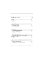
Installation 1-7 1.2.1 System Block Diagram 1-7 1.2.2 Layout of Motherboard 1-8 1.2.3 Quick Reference 1-9 1.3 CPU Installation 1-10 1.3.1 CPU Installation Procedure: Socket A 1-10 1.3.2 Frequency Selection: JCLK1 1-11 1.3.3 CPU Fan Connector: JCFAN1 1-12 1.3.4 System Fan Connector: JSFAN1 - Biostar M7VKQ | M7VKQ user's manual - Page 4
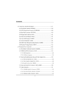
1.7.2.1 USB Connectors 1-24 1.7.2.2 LAN Port Connector 1-25 1.7.3 Serial and Parallel Interface Ports and Video Graphics Port 1-26 1.7.3.1 The Serial Interface port: COM1 1-26 1.7.3.2 Video Graphics Adapter Port: JVGA1 1-28 1.7.3.3 Parallel Interface Port: JPRNT1 1-29 1.7.4 Game and Audio Port - Biostar M7VKQ | M7VKQ user's manual - Page 5
BIOS Setup 2-1 2.1 Main Menu 2-3 2.2 Standard CMOS Features 2-6 2.3 Advanced BIOS Features 2-9 2.4 Advanced Chipset Features 2-14 2.5 Integrated Peripherals 2-17 2.6 Power Management Setup 2-22 2.7 PnP/PCI Configurations 2-28 2.8 PC Health Status 2-33 2.9 Frequency Control 2-34 3. Trouble - Biostar M7VKQ | M7VKQ user's manual - Page 6
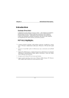
, this motherboard continues the audio ports, USB ports, a LAN port and a game port. 8 Contains on board IDE facilities for IDE devices such as hard disks and CD-ROM Drives. 8 Supports the AMD Supports popular operating systems such as Windows 95/98, Windows NT, Windows 2000, Windows ME, Windows XP - Biostar M7VKQ | M7VKQ user's manual - Page 7
AMD Socket-A for Athlon TM (Thunderbird TM )/ Athlon TM XP/ Duron TM processors. Running at 200/266 MHz Front Side Bus (FSB). Chipset − Chipset - VIA VT8361/ VT82C686B. − Chipset - LAN Chip Realtek RTL 8100 (Optional). Speed − Supports up to AMD Athlon TM XP 2000+ CPU core speeds. DRAM Memory - Biostar M7VKQ | M7VKQ user's manual - Page 8
Chapter 1 Motherboard Description BUS Slots − Three 32-bit PCI bus master slots. − One ISA slot. − One AMR slot. Flash Memory − Supports flash memory. − Supports ESCD Function. IDE Built-in On Board − Supports four IDE hard disk drives. − Supports PIO Mode 4, Master Mode, high performance hard - Biostar M7VKQ | M7VKQ user's manual - Page 9
Motherboard Description LAN Built-in On Board − 10 mb/s and 100 mb/s operation. − Compliant to PC99 standard. − Supports Wake-On-LAN function and remote wake-up. − Contains two large (2KB) independent receive and transmit FIFO's. − Supports playback of 9.8M bps MPEG-2 video with 30% headroom − Hoast - Biostar M7VKQ | M7VKQ user's manual - Page 10
Chapter 1 Motherboard Description − Multiple buffering and page flipping Universal Serial Bus − Supports two back Universal Serial Bus (USB) Ports and two front Universal serial Bus (USB) Ports (Optional). − Supports 48 MHz USB. Hardware Monitor Function − CPU Fan and System Fan Speed Monitor. − - Biostar M7VKQ | M7VKQ user's manual - Page 11
legal BIOS. Supports APM1.2. Supports USB Function. Supports ACPI. Operating System − Offers the highest performance for MS-DOS, Windows NT, Windows 2000, Windows 95/98, Windows ME, Windows XP, SCO UNIX etc. 1.1.3 Accessories − HDD Cable. − FDD Cable. − Flash Memory Writer for BIOS Update. − USB2 - Biostar M7VKQ | M7VKQ user's manual - Page 12
Chapter 1 Motherboard Description 1.2 Motherboard Installation 1.2.1 System Block Diagram SOCKET 462 CPU CLOCK ICW 230 CONTROL HOST BUS ADD DATA HOST BUS VGA RGB VIA VT8361 KLE 133 CNTL ADDR MEMORY D ATA I DE I DE AMR SLOT AC' 97 CODEC FLASH BIOS VT82C686B PCI BUS 2 USB CONN. PG. 7 - Biostar M7VKQ | M7VKQ user's manual - Page 13
Description 1.2.2 Layout of Motherboard Model No. M7VKQ JKBMS1 K/B & Mouse JLAN USB & LAN JCOM1 JKBV1 1 SOCKET A 1 JCFAN1 BAT1 JCMOS1 1 COM1 Parallel Port CPU1 JCLK1 1 DIMM1 DIMM2 PCI BUS SLOT ISA1 ISA SLOT IDE1 IDE2 FDD1 1 JSFAN1 VT82C686 BIOS U2 JPANEL1 2 10 1 9 JUSB2 1-8 - Biostar M7VKQ | M7VKQ user's manual - Page 14
Chapter 1 Motherboard Description 1.2.3 Quick Reference U TS R Q P A O N M B C D L K E F G J H I A. Back Audio Header (JAUDIO1) Q. DIMMs (DIMM1-2) G. PCI BUS Slots (PCI1-3) R. CPU FAN Header (JCFAN1) H. ISA BUS Slot (ISA1) S. Keyboard Voltage Selection (JKBV1)* I. Front USB - Biostar M7VKQ | M7VKQ user's manual - Page 15
Chapter 1 Motherboard Description 1.3 CPU Installation 1.3.1 CPU Installation Procedure: Socket A CPU 1. Pull the lever sideways away from the socket then raise the lever up to a 90-degree angle. 2. Locate Pin A in the socket and look for the white dot or cut edge in the CPU. Match Pin A with - Biostar M7VKQ | M7VKQ user's manual - Page 16
Chapter 1 SOCKET A Motherboard Description J C FA N 1 1 VT8361 DIMM1 DIMM2 JCLK1 1 VT82C686 BIOS JS FA N 1 1 JNFAN1 1 1.3.2 CPU Frequency Selection: JCLK1 JCKL1 *100MHz 1-2 133MHz 2-3 NOTES: The " * " mark indicate primitive value. 1-11 - Biostar M7VKQ | M7VKQ user's manual - Page 17
Chapter 1 Motherboard Description 1.3.3 CPU Fan Connector: JCFAN1 Pin No. 1 2 3 Assignment Ground +12V Sense 1.3.4 System Fan Connector: JSFAN1 (Optional) Pin No. 1 2 3 Assignment Ground +12V Sense 1.3.5 North Bridge Chipset Fan Header: - Biostar M7VKQ | M7VKQ user's manual - Page 18
Chapter 1 Motherboard Description 1.4 RAM Module Installation 1.4.1 DIMM DRAM Access Time: 3.3V Unbuffered SDRAM PC66/ PC100 and PC133 Type required. DRAM Type: 32MB/ 64MB/ 128MB/ 256MB/ 512MB DIMM Module (168pin). Total Memory Size (MB) 64 M 128 M 256 M 512 M 128 M 256 M 512 M 1024 M 160 M 288 M - Biostar M7VKQ | M7VKQ user's manual - Page 19
Chapter 1 Motherboard Description 1.4.2 How to install a DIMM Module 1. The DIMM socket has a " Plastic Safety Tab", and the DIMM memory module has an "Asymmetrical notch", so the DIMM memory module can only fit into the slot in one direction. 2. Push the tabs out. Insert the DIMM memory modules - Biostar M7VKQ | M7VKQ user's manual - Page 20
slots are a mean of adding or enhancing the motherboard's features and capabilities. With these efficient facilities, you can increase the motherboard's capabilities by adding hardware that performs tasks that are not part of the basic system. SOCKET A DIMM1 DIMM2 AMR Slot PCI Slots ISA Slot - Biostar M7VKQ | M7VKQ user's manual - Page 21
is an open Industry Standard Architecture that defines a hardware scalable riser card interface, which only supports audio and modem. 1.5.2 PCI (Peripheral Component Interconnect) Slots This motherboard is equipped with 3 standard PCI slots. PCI stands for Peripheral Component Interconnect, and it - Biostar M7VKQ | M7VKQ user's manual - Page 22
, Wake On LAN function and USB connection. Noticeably, a jumper has two or more pins covered by a plastic jumper cap, allowing the user to select a different system options. JKBV1 1 JATXPWR1 JWOL1 1 JAMRS1 1 SOCKET A VT8361 DIMM1 DIMM2 JCMOS1 1 IDE 1-2 FDD1 VT82C686 BIOS JPANEL1 JUSB2 2 10 - Biostar M7VKQ | M7VKQ user's manual - Page 23
It can be connected to the motherboard at the front panel connector. The speaker (onboard or offboard) provides error beep code information during the Power On Self-Test when the computer cannot use the video interface. The speaker is not connected to the audio subsystem and does not receive output - Biostar M7VKQ | M7VKQ user's manual - Page 24
This switch is usually open, and when it is closed, it will cause the motherboard to reset and run the POST (Power On Self Test). POW-LED (Power . APM (Advanced Power Management) must be enabled in the system BIOS, and the APM driver must be loaded. PWR (Power Button) This connector can be attached - Biostar M7VKQ | M7VKQ user's manual - Page 25
Ring Wake-Up and Soft Power Off are supported on this motherboard. This power connector supports instant power-on functionality, which means that CD-ROM, a 120MB Floppy (reserved for future BIOS) and other devices to IDE1 and IDE2. These connectors support the IDE hard disk cable provided. • IDE1 - Biostar M7VKQ | M7VKQ user's manual - Page 26
1.6.4 Floppy Disk Connector: FDD1 The motherboard provides a standard floppy disk connector (FDC) that supports 360K, 720K, 1.2M, 1.44M and 2.88M floppy disk types. This connector supports the provided floppy drive ribbon cables. 1.6.5 Wake On LAN Header: JWOL1 Pin No. 1 2 3 Assignment - Biostar M7VKQ | M7VKQ user's manual - Page 27
Chapter 1 Motherboard Description 1.6.8 AMR Codec Primary/Secondary Selection: JAMRS1 PIN Assignment On Secondary Off Primary 1.6.9 Keyboard Voltage Selection: JKBV1 (Optional) Pin No. 1-2 2-3 Assignment +5V (default) +5V Standby Voltage 1-22 - Biostar M7VKQ | M7VKQ user's manual - Page 28
Connectors JKBMS1 JLAN PS/2 Mouse LAN JPRNT1 Parallel AUD_GAME1 Game Port PS/2 USB Keyboard COM1 VGA1 Speaker Line In Mic Out In JCOM1 JVGA1 1.7.1 PS/2 Mouse / Keyboard Connector: JKBMS1 The motherboard provides a standard PS/2 mouse / Keyboard mini DIN connector for attaching a PS - Biostar M7VKQ | M7VKQ user's manual - Page 29
Description PS/2 Mouse / Keyboard Connectors Pin 1 2 3 4 5 6 Assignment Data No connection Ground +5 V (fused) Clock No connection 1.7.2 USB & LAN Port Connectors: JLAN 1.7.2.1 USB Connectors The motherboard provides a OHCI (Open Host Controller Interface) Universal Serial Bus Roots for attaching - Biostar M7VKQ | M7VKQ user's manual - Page 30
Chapter 1 Motherboard Description 1.7.2.2 LAN Port Connector This connector allows you to connect to the Internet through a Local Area Network (LAN). You can set up the connection by - Biostar M7VKQ | M7VKQ user's manual - Page 31
Chapter 1 Motherboard Description 1.7.3 Serial and Parallel Interface Ports and Video Graphics Port This system is equipped one serial port, one parallel port and a VGA port. These types of interface ports will be explained in this - Biostar M7VKQ | M7VKQ user's manual - Page 32
Chapter 1 Motherboard Description Connectivity The serial port can be used in many ways, and it may be necessary to become familiar with the pinout diagram. The following - Biostar M7VKQ | M7VKQ user's manual - Page 33
Graphics Adapter Port: JVGA1 This motherboard has built in video facilities. Your monitor will attach directly to JVGA1 connector on the motherboard. Pin No. 1 3 5 7 9 11 13 15 Assignment Red Blue Ground Ground +5V NC HSYNC DDC/CLK 5 1 15 11 JVGA1 Pin No. 2 4 6 8 10 12 14 Assignment Green - Biostar M7VKQ | M7VKQ user's manual - Page 34
Chapter 1 Motherboard Description 1.7.3.3 Parallel Interface Port: JPRNT1 Unlike the serial port, parallel interface port has been standardized, and it should not present any difficulty interfacing peripherals of - Biostar M7VKQ | M7VKQ user's manual - Page 35
Chapter 1 Motherboard Description 1.7.4 Game and Audio Port Connector: AUD_GAME1 This connector is composed of a Game port connector and an Audio port connector. Game Port Connector: Game port connector allows you to connect a joystick or a game pad for playing computer games. Also, you may play - Biostar M7VKQ | M7VKQ user's manual - Page 36
Chapter 1 1.7.5 Audio Subsystem JCDIN1 1 Motherboard Description SOCKET A DIMM1 DIMM2 JTAD1 1 JAUDIO1 2 10 1 VT8361 VT82C686 BIOS 1-31 - Biostar M7VKQ | M7VKQ user's manual - Page 37
Chapter 1 Motherboard Description 1.7.5.1 CD-ROM Audio-In Connector: JCDIN1 Pin No. 1 2 3 4 Assignment Left Channel Input Ground Ground Right Channel Input 1.7.5.2 Front Panel Audio Connector: JAUDIO1 Pin No. Assignment Pin No. Assignment 1 Mic In 2 3 Mic Power 4 5 AUD FPOUT R 6 7 - Biostar M7VKQ | M7VKQ user's manual - Page 38
fine-tuning of the chipset controls the entire system. The rest of this manual is intended to guide you through the process of configuring your system by using Setup. Plug and Play Support These AWARD BIOS supports the Plug and Play specification Version 1.0A complicant. ESCD (Extended System - Biostar M7VKQ | M7VKQ user's manual - Page 39
Version 2.2 of the Intel PCI (Peripheral Component Interconnect) local bus specification. DRAM Support SDRAM (Synchronous DRAM) are supported. Supported CPUs This AWARD BIOS supports the AMD AthlonTM / Duron TM CPU. Using Setup In general, you use the arrow keys to highlight items, press - Biostar M7VKQ | M7VKQ user's manual - Page 40
> to accept and enter the sub-menu. !! WARNING !! The information about BIOS defaults on manual (Figure 1,2,3,4,5,6,7,8) is just for reference, please refer to the BIOS installed on board, for update information. Figure 1. Main Menu Standard CMOS Features This submenu contains industry standard - Biostar M7VKQ | M7VKQ user's manual - Page 41
page shows the hardware Monitor information of the system. Load Optimized Defaults This selection allows you to reload the BIOS when the system is having problems particularly with the boot sequence. These configurations are factory settings optimized for this system. A confirmation message will be - Biostar M7VKQ | M7VKQ user's manual - Page 42
Chapter 2 BIOS Setup Set User Password If the Supervisor Password is not set, will not be able to change them. Save & Exit Setup Save all configuration changes to CMOS (memory) and exit setup. Confirmation message will be displayed before proceeding. Exit Without Saving Abandon all changes made - Biostar M7VKQ | M7VKQ user's manual - Page 43
Chapter 2 BIOS Setup 2.2 Standard CMOS Features The items in Standard CMOS Setup Menu are divided into 10 categories. Each category includes no, one or more than one - Biostar M7VKQ | M7VKQ user's manual - Page 44
Chapter 2 BIOS Setup Main Menu Selections This table shows the selections that you can make on the Main Menu. Item Options , 5.25 in 720K, 3.5 in Select the type of floppy disk drive installed in your system. 1.44M, 3.5 in 2.88M, 3.5 in Drive B None Video EGA/VGA CGA 40 Select the default - Biostar M7VKQ | M7VKQ user's manual - Page 45
N/A N/A Description Select the situation in which you want the BIOS to stop the POST process and notify you. Displays the amount of conventional memory detected during boot up. Displays the amount of extended memory detected during boot up. Displays the total memory available in the system. 2-8 - Biostar M7VKQ | M7VKQ user's manual - Page 46
used to protect the IDE Hard Disk boot sector. If this function is enabled and an attempt is made to write to the boot sector, BIOS will display a warning message on the screen and sound an alarm beep. The Choices: Disabled (default) Enabled Virus protection is disabled. Virus protection is - Biostar M7VKQ | M7VKQ user's manual - Page 47
Chapter 2 BIOS Setup CPU Internal Cache Depending on the CPU/chipset in use, you may be able to increase memory access time with this POST. Disabled Normal POST. First /Second/Third/ Boot Other Device These BIOS attempt to load the operating system from the devices in the sequence selected - Biostar M7VKQ | M7VKQ user's manual - Page 48
Chapter 2 BIOS Setup Boot Up Floppy Seek Enabling this option will test the floppy drives to determine if they have 40 or 80 tracks. Disabling this option - Biostar M7VKQ | M7VKQ user's manual - Page 49
version supported by the operation system running on this computer. The Choices: 1.4 (default), 1.1. OS Select For DRAM > 64MB A choice other than Non-OS2 is only used for OS2 systems with memory exceeding 64MB. The Choices: Non-OS2 (default), OS2. Video BIOS Shadow Determines whether video BIOS - Biostar M7VKQ | M7VKQ user's manual - Page 50
execution. The Choices: Enabled Optional ROM is shadowed. Disabled (default) Optional ROM is not shadowed. Note: For C8000 - DFFFF option - ROM on PCI BIOS, BIOS will automatically enable the shadow RAM. User does not have to select the item. Small Logo(EPA) Show This item allows you to enable - Biostar M7VKQ | M7VKQ user's manual - Page 51
Chapter 2 BIOS Setup 2.4 Advanced Chipset Features This submenu allows you to configure the specific features of the chipset installed on your system. This chipset manages bus speeds and access to the system memory resources, such as DRAM and external cache. It also coordinates communications with - Biostar M7VKQ | M7VKQ user's manual - Page 52
that the cache controller is enabled. The Choices: Enabled (default), Disabled. Video RAM Cacheable Select Enabled allows caching of the video BIOS, resulting in better system performance. However, if any program writes to this memory area, a system error may result. The Choices: Enabled (default - Biostar M7VKQ | M7VKQ user's manual - Page 53
Support Select Enabled if your system contains a Universal Serial Bus (USB) controller and also you have a USB keyboard. The Choices: Disabled (default), Enabled. OnChip Sound The default setting of this item utilizes an onboard sound chip for audio output. There is no need to buy and insert - Biostar M7VKQ | M7VKQ user's manual - Page 54
Peripherals Figure 5. Integrated Peripherals BIOS Setup Onboard PCI LAN This item allows you to Enabled/ Disabled Onboard PCI LAN function. The Choices: Enabled (default), Disabled. OnChip IDE Channel 0/1 The motherboard chipset contains a PCI IDE interface with support for two IDE channels - Biostar M7VKQ | M7VKQ user's manual - Page 55
(Windows 95 OSR2 or a third party IDE bus master driver). If your hard drive and your system software both support Ultra DMA/100, select Auto to enable BIOS support. The Choices: Auto (default), Disabled. Init Display First With systems that have multiple video cards, this option determines whether - Biostar M7VKQ | M7VKQ user's manual - Page 56
Chapter 2 BIOS Setup Onboard FDD Controller Select Enabled, if your system has a floppy disk controller (FDC) installed on the system board, and if you wish to use - Biostar M7VKQ | M7VKQ user's manual - Page 57
2 BIOS Setup Port. Select Normal unless you are certain your hardware and software both support EPP or ECP mode. The Choice: Normal (default), EPP, ECP, Audio This field controls the onboard legency audio. The Choices: Enabled (default), Disabled. Sound Blaster Hardware SoundBlaster Pro for Windows - Biostar M7VKQ | M7VKQ user's manual - Page 58
Chapter 2 BIOS Setup SB DMA Select Change the SoundBlaster Pro direct memory access setting. The Choices: DMA0, DMA1 (default), DMA2, DMA3. MPU-401 Enable or Disable MPU-401 function. The Choices: Disabled (default), Enabled. MPU-401 I/O Address Change the SoundBlaster Pro MPU-401 I/O address. The - Biostar M7VKQ | M7VKQ user's manual - Page 59
Chapter 2 BIOS Setup 2.6 Power Management Setup The Power Management Setup Menu allows you to configure your system to utilize energy conservation and power up/power down features. - Biostar M7VKQ | M7VKQ user's manual - Page 60
Chapter 2 BIOS Setup Power Management Option This category allows you to select Mode = 1 hr Suspend Mode = 1 hr. HDD Power Down = 15 min Max. Power Saving Maximum power management only available for sl CPU's. Doze Mode = 1 min Standby Mode = 1 min. Suspend Mode = 1 min. HDD Power Down = 1 min. - Biostar M7VKQ | M7VKQ user's manual - Page 61
the set time of system inactivity, all devices except the CPU will be shut off. The Choices: Disabled (default), 1 BIOS will ignore APM when power Management is on. System Bios will wait for APM's prompt before it enters any PM mode. Video Off Option This field determines when to activate the video - Biostar M7VKQ | M7VKQ user's manual - Page 62
Chapter 2 BIOS Setup buffer. Blank Screen This option only writes blanks to the video buffer. DPMS Support Initial display power management signaling. Modem Use IRQ This determines the IRQ, which can be applied in MODEM use. The Choices: 3 (default), 4, 5, 7, 9, 10, 11, NA. - Biostar M7VKQ | M7VKQ user's manual - Page 63
Chapter 2 BIOS Setup PCI Master When set to On, any event occurring at PCI LAN add-on card which support power on function. It should also support the wake-up on LAN jump. Disabled (default) Wake up on LAN/Ring not supported Enabled Wake up on LAN/Ring supported Modem Ring Resume To use - Biostar M7VKQ | M7VKQ user's manual - Page 64
Chapter 2 BIOS Setup awaken a system, which has been powered down. The Choices: ON (default), OFF. IRQs Activity Monitoring Press Enter to access another sub menu used to - Biostar M7VKQ | M7VKQ user's manual - Page 65
BIOS Setup 2.7 PnP/PCI Configurations This section describes configuring the PCI bus system. PCI, or Personal Computer Interconnect, is a system, which allows I/O devices to operate at speeds nearing the speed of the CPU PnP operating system like Window™ 95. When set to NO, BIOS will initialize all - Biostar M7VKQ | M7VKQ user's manual - Page 66
update ESCD to the memory locations. These locations (4K) are reserved in the system BIOS. If the Disabled (default) option is chosen, the system's ESCD will update PnP The above settings will be shown on the screen only if "Manual" is chosen for the resources controlled by function. Legacy is the - Biostar M7VKQ | M7VKQ user's manual - Page 67
Chapter 2 BIOS Setup IRQ Resources This submenu will allow you to assign each interrupts. This is only configurable when "Resources Controlled By" is set to "Manual". DMA Resources When resources are controlled manually, assign each system DMA channel a type, depending on the type of device using - Biostar M7VKQ | M7VKQ user's manual - Page 68
for the USB. The Choices: Enabled (default), Disabled. PCI Master Pipeline Req This item allows you to enable/disable the PCI master pipeline request feature. The Choices: Enabled (default), Disabled. P2C/C2P Concurrency This item allows you to enable/disable the PCI to CPU, CPU to PCI concurrency - Biostar M7VKQ | M7VKQ user's manual - Page 69
Chapter 2 BIOS Setup PCI#2 Access #1 Retry When enabled, PCI#2 will be disconnected if max retries are attempted without success. When disabled, PCI#2 will not be disconnected until - Biostar M7VKQ | M7VKQ user's manual - Page 70
Chapter 2 2.8 PC Health Status Figure 8. PC Health Status BIOS Setup Current CPU Temp This field displays the current temperature of CPU. Show H/W Monitor in POST If your computer contains a monitoring system, it will show PC health status during POST stage. The item offers several delay time - Biostar M7VKQ | M7VKQ user's manual - Page 71
2.9 Frequency Control Frequency Control BIOS Setup Auto Detect DIMM / PCI Clk This item allows you to enable/disable auto detect DIMM/PCI Clock. The Choices: Enabled (default), Disabled. CPU Host / PCI / Spread Spec. This item allows you to select CPU Host Clock (CPU / PCI). If unfortunately, the - Biostar M7VKQ | M7VKQ user's manual - Page 72
support. socket socket, repair outlet, reset circuit breaker or replace fuse. PROBLEM System inoperative. Keyboard lights are on, power indicator lights are lit, hard drive is spinning. PROBABLE CAUSE DIAGNOSIS SOLUTION Memory DIMM is partially dislodged from the slot on the motherboard - Biostar M7VKQ | M7VKQ user's manual - Page 73
Chapter 3 Trouble Shooting PROBLEM System does not boot from hard disk drive, can be Damaged hard disk or disk controller. Format hard disk; if Contact technical unable to do so the hard support. disk may be defective. Hard disk directory or FAT is scrambled. Run the FDISK program, format the - Biostar M7VKQ | M7VKQ user's manual - Page 74
Trouble Shooting PROBLEM configuration program. Replace any incorrect information. SOLUTION Review system's equipment . Make sure correct information PROBLEM DIAGNOSIS SOLUTION Check the power connectors to monitor and to system. Make sure monitor is connected to display card. See instructions - Biostar M7VKQ | M7VKQ user's manual - Page 75
Chapter 3 Trouble Shooting No screen. PROBLEM PROBABLE CAUSE Memory problem. Computer virus. DIAGNOSIS SOLUTION Reboot computer. Reinstall memory, make sure that all memory modules are installed in correct sockets. Use anti-virus programs to detect and clean viruses. PROBLEM Screen goes blank - Biostar M7VKQ | M7VKQ user's manual - Page 76
Chapter 3 Trouble Shooting No color on screen. PROBLEM PROBABLE CAUSE Faulty Monitor. CMOS incorrectly set up. DIAGNOSIS SOLUTION If possible, connect monitor to another system. If no color replace monitor. Call technical support. C: drive failure. PROBLEM PROBABLE CAUSE Hard drive cable - Biostar M7VKQ | M7VKQ user's manual - Page 77
Chapter 3 Trouble Shooting PROBLEM Missing operating system on hard drive. PROBABLE CAUSE CMOS setup has been changed. DIAGNOSIS SOLUTION Run setup and select correct drive type. PROBLEM Certain keys do not function. PROBABLE CAUSE Keys jammed or defective. DIAGNOSIS SOLUTION Replace - Biostar M7VKQ | M7VKQ user's manual - Page 78
12/06/2001
-
 1
1 -
 2
2 -
 3
3 -
 4
4 -
 5
5 -
 6
6 -
 7
7 -
8
-
9
-
10
-
11
-
12
-
13
-
14
-
15
-
16
-
17
-
18
-
19
-
20
-
21
-
22
-
23
-
24
-
25
-
26
-
27
-
28
-
29
-
30
-
31
-
32
-
33
-
34
-
35
-
36
-
37
-
38
-
39
-
40
-
41
-
42
-
43
-
44
-
45
-
46
-
47
-
48
-
49
-
50
-
51
-
52
-
53
-
54
-
55
-
56
-
57
-
58
-
59
-
60
-
61
-
62
-
63
-
64
-
65
-
66
-
67
-
68
-
69
-
70
-
71
-
72
-
73
-
74
-
75
-
76
-
77
-
78
 |
 |

M7VKQ
Federal Communications Commission
(F.C.C.) Statement
This device complies with Part 15 of the FCC Rules. Operation of this device is
subject to the following two conditions: (1) this device may not cause harmful
interference, and (2) this device must accept any interference received, including
interference that may cause undesired operation.
Accessories: This device has been tested and found to comply with the limits of a
Class B digital device; the accessories associated with this equipment are as
follows:
1. Shielded serial cable. (Can be obtained from multiple retail outlets)
2. Shielded printer cable. (Can be obtained from multiple retail outlets)
3. Shielded video cable. (Can be obtained from multiple retail outlets)
4. Shielded power cord. (Provided by manufacturer)
These accessories are required to ensure compliance with FCC Rules. It is the
responsibility of the user to provide and use these accessories properly.
This equipment has been tested and found to comply with the limits of a Class B
digital device, pursuant of Part 15 of the FCC Rules. These limits are designed to
provide reasonable protection against harmful interference in a residential
installation. This equipment generates, uses and radiates radio frequency energy
and, if you did not installed and used in accordance with the instructions, may cause
harmful interference in the radio communications. There is no guarantee that
interference will not occur in a particular installation. If this equipment does cause
harmful interference to radio or television reception, which can be determined by
turning the equipment off and on, you are encouraged to try to correct the
interference by one or more of the following measures:
1. Reorient / relocate the receiving antenna.
2. Increase the separation between the equipment and the receiver.
3. Connect the equipment into an outlet from a different circuit where the
receiver is connected.
4. Consult the dealer or an experienced radio/TV technician for help.
Caution: Changes or modifications that is not expressly approved by the
manufacturer could void the user’s authority to operate the equipment.
Disclaimer
The vendor makes no representations or warranties with respect to the contents
here of and specially the vendor disclaims any implied warranties of
merchantability or fitness for any purpose. Further, the vendor reserves the right to