Biostar MCP6PBM2 Setup Manual
Biostar MCP6PBM2 Manual
 |
View all Biostar MCP6PBM2 manuals
Add to My Manuals
Save this manual to your list of manuals |
Biostar MCP6PBM2 manual content summary:
- Biostar MCP6PBM2 | Setup Manual - Page 1
MCP6PB M2+ Setup Manual FCC Information and Copyright This equipment has been tested and found to radiate radio frequency energy and, if not installed and used in accordance with the instructions, may cause harmful interference to radio communications. There is no guarantee that interference will - Biostar MCP6PBM2 | Setup Manual - Page 2
Raid Arrays 19 4.3 How RAID Works 19 Chapter 5: Useful Help 21 5.1 Driver Installation Note 21 5.2 Software 22 5.3 Award BIOS Beep Code 23 5.4 Extra Information 23 5.5 Troubleshooting 24 Appendix: SPEC In Other Languages 26 German...26 French ...28 Italian...30 Spanish - Biostar MCP6PBM2 | Setup Manual - Page 3
MCP6PB M2+ 1.1 BEFORE YOU START Thank you for choosing our product. Before you start installing the motherboard, please make sure you follow the instructions Rear I/O Panel for ATX Case X 1 Installation Guide X 1 Fully Setup Driver CD X 1 (full version manual files inside) FDD Cable X 1 (optional) - Biostar MCP6PBM2 | Setup Manual - Page 4
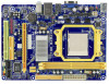
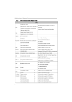
Motherboard Manual 1.3 MOTHERBOARD FEATURES SPEC Socket AM2 / AM2+ AMD 64 Architecture enables 32 and 64 bit AMD Athlon 64 / Athlon 64 FX / Athlon 64 x2 CPU computing / Sempron / PhenomX3 / X4 processors Supports Hyper Transport and PowerNow (Maximum Watt: 95W) Support HyperTransport 1.0 - Biostar MCP6PBM2 | Setup Manual - Page 5
Audio Jack Board Size 170 mm(W) x 235 mm(L) Special Features RAID 0 / 1 OS Support Windows XP / Vista / 7 MCP6PB M2+ SPEC x1 CPU Fan power x3 Provide Audio-In/Out and microphone connection MicroATX Biostar Reserves the right to add or remove support for any OS With or without notice. 1.4 - Biostar MCP6PBM2 | Setup Manual - Page 6
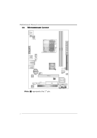
Motherboard Manual 1.5 MOTHERBOARD LAYOUT JKBMS J KB_PWR J ATXPWR2 J ATXPWR1 Socket A M2+ JVG A D IM M A1 D IM M B1 JUSB1 JCFA N JUS B PW R1 JUSBLAN1 JAUDIO1 BAT1 JCO M LAN JA UDIO F Codec JP RNT GeForce 6150SE PEX16_1 BIOS FDD PCI1 Note: ■ represents the 1st pin. J USBPWR2 JU S B3 - Biostar MCP6PBM2 | Setup Manual - Page 7
MCP6PB M2+ CHAPTER 2: HARDWARE INSTALLATION 2.1 INSTALLING CENTRAL PROCESSING UNIT (CPU) Step 1: Remove the socket protection cap. Step 2: Pull the lever toward direction A from the socket and then raise the lever up to a 90-degree angle. - Biostar MCP6PBM2 | Setup Manual - Page 8
Motherboard Manual Step 4: Hold the CPU down firmly, and then close the lever toward direct B to complete the installation. Step 5: Put the CPU Fan on the CPU and buckle it. Connect the CPU FAN power cable to the JCFAN. This completes the installation. Note: Please update the BIOS to the latest - Biostar MCP6PBM2 | Setup Manual - Page 9
MCP6PB M2+ 2.2 FAN HEADERS These fan headers support cooling-fans built in the computer. The fan cable and connector may be different according to the fan manufacturer. Connect the fan cable to the connector while matching the black wire to pin#1. JCFAN: CPU Fan Header Pin Assignment 1 1 Ground - Biostar MCP6PBM2 | Setup Manual - Page 10
DIM MA1 DIM MB1 Motherboard Manual 2.3 INSTALLING SYSTEM MEMORY A. Memory Modules 1. Unlock a DIMM slot by pressing the retaining clips outward. Align a DIMM on the slot so that the notch on the - Biostar MCP6PBM2 | Setup Manual - Page 11
Location DDR2 Module DIMMA1 256MB/512MB/1GB/2GB DIMMB1 256MB/512MB/1GB/2GB MCP6PB M2+ Total Memory Size Max is 4GB. C. Dual Channel Memory installation To trigger the Dual Channel function of the motherboard, the memory module must meet the following requirements: Install memory module of - Biostar MCP6PBM2 | Setup Manual - Page 12
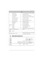
Motherboard Manual 2.4 CONNECTORS AND SLOTS FDD: Floppy Disk Connector The motherboard provides a standard floppy disk connector that supports 360K, 720K, 1.2M, 1.44M and 2.88M floppy disk types. This connector supports the provided floppy drive ribbon cable. 2 34 1 33 IDE: IDE/ATAPI Connector - Biostar MCP6PBM2 | Setup Manual - Page 13
MCP6PB M2+ PEX16_1: PCI-Express Gen2 x16 Slot - PCI-Express 1.0a compliant. - Maximum theoretical realized bandwidth of 4GB/s simultaneously per direction, for an aggregate of 8GB/s totally. - PCI-Express supports a raw bit-rate of 2.5Gb/s on the data pins. - 2X bandwidth over the traditional PCI - Biostar MCP6PBM2 | Setup Manual - Page 14
Motherboard Manual CHAPTER 3: HEADERS & JUMPERS SETUP 3.1 HOW TO SETUP JUMPERS The illustration shows how to set up jumpers. When the jumper cap is placed on pins, the - Biostar MCP6PBM2 | Setup Manual - Page 15
MCP6PB M2+ JATXPWR1: ATX Power Source Connector This connector allows user to connect 11 +12V 12 +3.3V JATXPWR2: ATX Power Source Connector By connecting this connector, it will provide +12V to CPU power circuit. 4 3 1 2 Pin Assignment 1 +12V 2 +12V 3 Ground 4 Ground Note: Before - Biostar MCP6PBM2 | Setup Manual - Page 16
Motherboard Manual JUSB2/JUSB3: Headers for USB 2.0 Ports at 8 Ground 9 NC 10 Key SATA1/SATA2: Serial ATA Connectors The motherboard has a PCI to SATA Controller with 2 channels SATA interface, it satisfies the SATA 2.0 spec and with transfer rate of 3.0Gb/s. SATA2 SATA1 14 7 Pin Assignment - Biostar MCP6PBM2 | Setup Manual - Page 17
MCP6PB M2+ JAUDIOF: Front Panel Audio Header This header allows user to Jack Sense 7 Front Sense 8 Key 9 Left line in 10 Jack Sense 1 9 JCOM: Serial port Connector The motherboard has a Serial Port Connector for connecting RS-232 Port. 2 10 1 9 Pin Assignment 1 Carrier detect 2 Received - Biostar MCP6PBM2 | Setup Manual - Page 18
Motherboard Manual JCMOS1: Clear CMOS Header By placing the jumper on pin2-3, it allows user to restore the BIOS safe setting and the CMOS data, please carefully follow the procedures to avoid damaging the motherboard. 31 Pin 1-2 Close: Normal Operation (default). 31 31 Pin 2-3 Close: Clear CMOS - Biostar MCP6PBM2 | Setup Manual - Page 19
MCP6PB M2+ JPRNT: Printer Port Connector This header allows you to connect printer port on the PC. 2 1 25 Pin Assignment 1 -Strobe 2 -ALF 3 Data 0 4 -Error 5 Data 1 6 -Init 7 Data 2 8 - - Biostar MCP6PBM2 | Setup Manual - Page 20
Motherboard Manual JUSBPWR1/JUSBPWR2: Power Source Headers for USB Ports Pin 1-2 Close: JUSBPWR1: +5V for USB ports at JUSB1/JUSBLAN1. JUSBPWR2: +5V for USB ports at front - Biostar MCP6PBM2 | Setup Manual - Page 21
MCP6PB M2+ CHAPTER 4: RAID FUNCTIONS 4.1 OPERATING SYSTEM Supports Windows XP and Windows Vista. 4.2 RAID ARRAYS RAID supports the following types of RAID arrays: RAID 0: RAID 0 defines a disk striping scheme that improves disk read and write times for many applications. RAID 1: RAID 1 defines - Biostar MCP6PBM2 | Setup Manual - Page 22
Motherboard Manual RAID 1: Every read and write is actually carried out in parallel across can be applied for high-availability solutions, or as a form of automatic backup that eliminates tedious manual backups to more expensive and less reliable media. Features and Benefits Drives: Minimum 2, and - Biostar MCP6PBM2 | Setup Manual - Page 23
USEFUL HELP MCP6PB M2+ 5.1 DRIVER INSTALLATION NOTE After you installed your operating system, please insert the Fully Setup Driver CD into your optical drive and install the driver for better system performance. You will see the following window after you insert the CD The setup guide will auto - Biostar MCP6PBM2 | Setup Manual - Page 24
Manual 5.2 SOFTWARE Installing Software 1. Insert the Setup CD to the optical drive. The drivers installation program would appear if the Autorun function has been enabled. 2. Select Software Installation, and then click on the respective software title. 3. Follow the on-screen instructions - Biostar MCP6PBM2 | Setup Manual - Page 25
MCP6PB M2+ 5.3 AWARD BIOS BEEP CODE Beep Sound Meaning One long beep followed by two short Video card not found or video card beeps memory bad High-low siren sound CPU overheated System will shut down automatically One Short beep when system boot-up No error found during POST Long beeps - Biostar MCP6PBM2 | Setup Manual - Page 26
Motherboard Manual 5.5 TROUBLESHOOTING Probable Solution 1. There is no power in the system. 1. Make sure power cable is Power LED does not shine; the securely plugged in. fan of the power supply does not 2. Replace cable. work 3. Contact technical support disk controller board. Make Review - Biostar MCP6PBM2 | Setup Manual - Page 27
MCP6PB M2+ This page is intentionally left blank. 25 - Biostar MCP6PBM2 | Setup Manual - Page 28
Motherboard Manual APPENDIX: SPEC IN OTHER LANGUAGES GERMAN Spezifikationen Sockel AM2 / AM2+ Die AMD 64-Architektur unterstützt eine 32-Bit- und AMD Athlon 64 / Athlon 64 FX / Althlon 64 CPU 64-Bit-Datenverarbeitung X2 / Sempron / PhenomX3 / X4 Unterstützt Hyper Transport und PowerNow - Biostar MCP6PBM2 | Setup Manual - Page 29
MCP6PB M2+ Spezifikationen PCI Express x16 CPU-Lüfter-Sockel Onboard-Ans System-Lüfter-Sockel chluss "CMOS löschen"-Sockel CPU (L) e Sonderfunkti Unterstützt RAID 0 / 1 onen OS-Unterstü Windows XP / Vista / 7 tzung Biostar behält sich das Recht vor, ohne Ankündigung die Unterstützung - Biostar MCP6PBM2 | Setup Manual - Page 30
Motherboard Manual FRENCH SPEC Socket AM2 / AM2 Prend en charge la DDR2 1066 (by AM2+ CPU) Chaque DIMM prend en charge des DDR2 Les charge Graphiques Integré dans la chipset GeForce 6150SE Mémoire vidéo partag écification SATA Version 2.0 10 / 100 Mb/s négociation automatique Half / Full duplex - Biostar MCP6PBM2 | Setup Manual - Page 31
MCP6PB M2+ Connecteur du panneau avant SPEC x1 Prend en charge les équipements du panneau 235 mm (H) carte Fonctionnal ités Prise en charge RAID 0 / 1 spéciales Support SE Windows XP / Vista / 7 Biostar se réserve le droit d'ajouter ou de supprimer le support de SE avec ou sans préavis. 29 - Biostar MCP6PBM2 | Setup Manual - Page 32
Motherboard Manual ITALIAN SPECIFICA CPU Socket AM2 / AM2+ L'architettura AMD 64 abilita la co mputazione 32 Processori AMD AM2+ CPU) 256MB/512MB/1GB/2GB DIMM registrati e DIMM ECC non sono supportati Grafica Integrata nel Chipset GeForce 6150SE La memoria video condivisa massima è di 256 MB - Biostar MCP6PBM2 | Setup Manual - Page 33
MCP6PB M2+ SPECIFICA Connettore audio frontale x1 Supporta la funzione audio pannello frontale Collettore ventolina CPU Alimentazione ventolina CPU iche Supporto RAID 0 / 1 speciali Sistemi Biostar si riserva il diritto di aggiungere o operativi Windows XP / Vista / 7 rimuovere il supporto - Biostar MCP6PBM2 | Setup Manual - Page 34
Motherboard Manual SPANISH Especificación Conector AM2 / AM2+ Procesadores AMD Athlon 64 / Athlon 64 La arquitectura AMD 64 permite el procesado de 32 y CPU Ranuras Ranura PCI Express x16 Ranura PCI Negociación de 10 / 100 Mb/s Funciones Half / Full dúplex Salida de sonido de 5.1 canales - Biostar MCP6PBM2 | Setup Manual - Page 35
MCP6PB M2+ Especificación Conector SATA X2 Cada conector soporta 1 dispositivos SATA Conector de panel frontal X1 Soporta instalaciones en el panel frontal Conector de sonido frontal X1 Soporta funciones de sonido en el panel frontal Cabecera de ventilador de CPU X1 Fuente de alimentación de - Biostar MCP6PBM2 | Setup Manual - Page 36
Motherboard Manual PORTUGUESE ESPECIFICAÇÕES Socket AM2 / AM2+ Processadores AMD Athlon 64 / Athlon 64 A arquitectura AMD 64 permite uma computação de CPU FX / Althlon 64 X2 / Sempron / PhenomX3 32 e 64 bits / X4 Suporta as tecnologias Hyper Transport e PowerNow (Watt máximo: 95W) Suporta - Biostar MCP6PBM2 | Setup Manual - Page 37
MCP6PB M2+ ESPECIFICAÇÕES Conector SATA x2 Cada conector suporta 1 dispositivo SATA Conector do painel frontal x1 Para suporte de várias funções no painel frontal Conector de áudio frontal x1 Suporta a função de áudio no painel frontal Conector da ventoinha da CPU Alimentação da ventoinha - Biostar MCP6PBM2 | Setup Manual - Page 38
Motherboard Manual POLISH SPEC Procesor Socket AM2 / AM2+ Architektura AMD 64 umożliwia przetwarzanie 32 i 64 AMD Athlon Grafika Zintegrowana w chipsecie GeForce 6150SE Maks. wielkość współdzielonej pamięci video wynosi 256 MB IDE Zintegrowany kontroler IDE Ultra DMA 33 / 66 / 100 / 133 - Biostar MCP6PBM2 | Setup Manual - Page 39
MCP6PB M2+ SPEC Złącze główkowe wentylatora procesora Zasilanie wentylatora procesora (z funkcją Smart mm (W) Funkcje specjalne Obsługa RAID 0 / 1 Obsluga systemu Windows XP / Vista / 7 operacyjne go Biostar zastrzega sobie prawo dodawania lub odwoływania obsługi dowolnego systemu operacyjnego - Biostar MCP6PBM2 | Setup Manual - Page 40
Motherboard Manual RUSSIAN СПЕЦ CPU AM2 / AM2+ AMD Athlon 64 / Athlon 64 AMD 64 ный FX / Althlon 256МБ/512МБ/1ГБ/2ГБ DDR2 DDR2 DDR2 533 / 667 / 800 DDR2 1066 (by AM2+ CPU DIMM and ECC DIMM Super I/O ITE 8718F Super I/O. ITE "Smart Guardian GeForce 6150SE 256 - Biostar MCP6PBM2 | Setup Manual - Page 41
MCP6PB M2+ СПЕЦ x1 x1 x1 x1 CMOS x1 USB 2 USB x2 24 вывод) x1 4 вывод) x1 USB-порт x4 ода x3 170 мм (Ш) X 235 мм (В) ые RAID 0 / 1 ие стики Windows XP / Vista / 7 а OS Biostar OS 39 - Biostar MCP6PBM2 | Setup Manual - Page 42
Motherboard Manual ARABIC AM2 / AM2 AMD Athlon 64 / Athlon 64 FX / Sempron 32و 64ﺑﺖAMD 64 533 DDR2 4 1066 DDR2 256/512 DDR2 DIMM )(DDR2 1066 is by AM2+ CPU 1و 2 ECC DIMM 256 GeForce 6150SE Ultra DMA 33 / 66 - Biostar MCP6PBM2 | Setup Manual - Page 43
Smart Fan USB 1 1 1 1 2 1 1 1 1 MCP6PB M2+ CMOS USB 24 4 1 PS/2 1 PS/2 1 VGA 1 4 USB ﻋﺪ3 Biostar 170 235 X RAID 0 / 1 Windows XP / Vista / 7 41 - Biostar MCP6PBM2 | Setup Manual - Page 44
Motherboard Manual JAPANESE 仕様 Socket AM2 / AM2+ AMD 64 32ビットと64 AMD Athlon 64 / Athlon 64 FX / Althlon 64 能です CPU X2 / Sempron / PhenomX3 / X4 ATA 最高3Gb SATA 2.0 LAN Realtek RTL 8201CL PHY 10 / 100 Mb HD ALC662 ト 5.1 PCI Express x16スロット x1 スロット PCIスロット x1 IDE - Biostar MCP6PBM2 | Setup Manual - Page 45
CPU CMOS USBコネクタ 24ピン) 4ピン) PS/2 PS/2マウス VGAポート I/O LANポート USBポート 170 mm (幅) X 235 mm (高さ) RAID 0 / 1 OS Windows XP / Vista / 7 MCP6PB M2+ 仕様 x1 x1 x1 CPU x1 x1 2 USB x2 ます x1 x1 x1 1 x1 x1 x1 x1 x1 x4 x3 Biostar OS 2009/09/18 43
-
 1
1 -
 2
2 -
 3
3 -
 4
4 -
 5
5 -
 6
6 -
 7
7 -
8
-
9
-
10
-
11
-
12
-
13
-
14
-
15
-
16
-
17
-
18
-
19
-
20
-
21
-
22
-
23
-
24
-
25
-
26
-
27
-
28
-
29
-
30
-
31
-
32
-
33
-
34
-
35
-
36
-
37
-
38
-
39
-
40
-
41
-
42
-
43
-
44
-
45
 |
 |

MCP6PB M2+ Setup Manual
FCC Information and Copyright
This equipment has been tested and found to comply with the limits of a Class
B digital device, pursuant to Part 15 of the FCC Rules. These limits are designed
to provide reasonable protection against harmful interference in a residential
installation. This equipment generates, uses, and can radiate radio frequency
energy and, if not installed and used in accordance with the instructions, may
cause harmful interference to radio communications. There is no guarantee
that interference will not occur in a particular installation.
The vendor makes no representations or warranties with respect to the
contents here and specially disclaims any implied warranties of merchantability
or fitness for any purpose. Further the vendor reserves the right to revise this
publication and to make changes to the contents here without obligation to
notify any party beforehand.
Duplication of this publication, in part or in whole, is not allowed without first
obtaining the vendor’s approval in writing.
The content of this user’s manual is subject to be changed without notice and
we will not be responsible for any mistakes found in this user’s manual. All the
brand and product names are trademarks of their respective companies.