Biostar N68S Setup Manual
Biostar N68S Manual
 |
View all Biostar N68S manuals
Add to My Manuals
Save this manual to your list of manuals |
Biostar N68S manual content summary:
- Biostar N68S | Setup Manual - Page 1
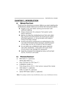
can radiate radio frequency energy and, if not installed and used in accordance with the instructions, may cause harmful interference to radio communications. There is no guarantee that interference will not occur in a particular installation. The vendor makes no representations or warranties with - Biostar N68S | Setup Manual - Page 2
3 1.5 Motherboard Layout 4 Chapter 2: Hardware Installation 5 2.1 Installing Central Processing Unit (CPU 5 2.2 FAN Headers 7 2.3 Installing System Memory 8 2.4 Connectors and Slots 10 Chapter 3: Headers & Jumpers Setup 12 3.1 How to Setup Jumpers 12 3.2 Detail Settings 12 - Biostar N68S | Setup Manual - Page 3
Cable X 2 Rear I/O Panel for ATX Case X 1 Installation Guide X 1 Fully Setup Driver CD X 1 (full version manual files inside) FDD Cable X 1 (optional) USB 2.0 Cable X1 (optional) Serial ATA Power Cable X 1 (optional) Note: The package contents may be differed by area or your motherboard version. 1 - Biostar N68S | Setup Manual - Page 4
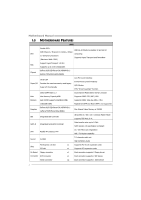
Max Memory Capacity 4GB Supports DDR2 533 / 667 / 800 Memory Each DIMM supports 256MB/512MB/ Supports DDR2 1066 (by AM2+ CPU) 1GB/2GB DDR2 Registered DIMM and ECC DIMM is not supported Graphics GeForce 6150 SE/nForce 430 (MCP6P M2+) GeForce 7025/nForce 630a (N68S) Max Shared Video Memory is - Biostar N68S | Setup Manual - Page 5
Back Panel VGA port I/O LAN port USB Port Audio Jack Board Size 170 mm(W) x 235 mm(L) Special Features RAID 0 / 1 OS Support Windows XP / Vista / 7 MCP6PB M2+/N68S SPEC x1 Supports front panel facilities x1 Supports front panel audio function x1 CPU Fan power supply (with Smart - Biostar N68S | Setup Manual - Page 6
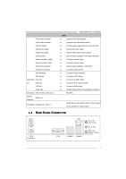
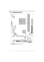
Motherboard Manual 1.5 MOTHERBOARD LAYOUT JKB MS JKB_PWR JATXPWR2 JATXPWR 1 Socket AM2+ JVGA DIMMA1 DIMMB1 J USB1 JCFAN JUSBPWR1 JUSBLA N1 JA UDIO1 BAT1 JCOM LAN JAU DIOF Codec JPRNT GeFo rc e 61 50SE /7 025 n Force 43 0/630a PEX16_1 BIOS FDD PCI1 Note: ■ represents the 1st pin. - Biostar N68S | Setup Manual - Page 7
MCP6PB M2+/N68S CHAPTER 2: HARDWARE INSTALLATION 2.1 INSTALLING CENTRAL PROCESSING UNIT (CPU) Step 1: Remove the socket protection cap. Step 2: Pull the lever toward direction A from the socket and then raise the lever up to a 90-degree angle. Step 3: Look for the white triangle on socket, and the - Biostar N68S | Setup Manual - Page 8
Motherboard Manual Step 4: Hold the CPU down firmly, and then close the lever toward direct B to complete the installation. Step 5: Put the CPU Fan on the CPU and buckle it. Connect the CPU FAN power cable to the JCFAN. This completes the installation. Note: Please update the BIOS to the latest - Biostar N68S | Setup Manual - Page 9
MCP6PB M2+/N68S 2.2 FAN HEADERS These fan headers support cooling-fans built in the computer. The fan cable and connector may be different according to the fan manufacturer. Connect the fan cable to the connector while matching the black wire to pin#1. JCFAN: CPU Fan Header Pin Assignment 1 1 - Biostar N68S | Setup Manual - Page 10
DIM MA1 DIM MB1 Motherboard Manual 2.3 INSTALLING SYSTEM MEMORY A. Memory Modules 1. Unlock a DIMM slot by pressing the retaining clips outward. Align a DIMM on the slot so that the notch on the DIMM matches the break on the - Biostar N68S | Setup Manual - Page 11
Socket Location DDR2 Module DIMMA1 256MB/512MB/1GB/2GB DIMMB1 256MB/512MB/1GB/2GB MCP6PB M2+/N68S Total Memory Size Max is 4GB. C. Dual Channel Memory installation To trigger the Dual Channel function of the motherboard, the memory module must meet the following requirements: Install memory - Biostar N68S | Setup Manual - Page 12
Motherboard Manual 2.4 CONNECTORS AND SLOTS FDD: Floppy Disk Connector The motherboard provides a standard floppy disk connector that supports 360K, 720K, 1.2M, 1.44M and 2.88M floppy disk types. This connector supports the provided floppy drive ribbon cable. 2 34 1 33 IDE: IDE/ATAPI Connector - Biostar N68S | Setup Manual - Page 13
direction, for an aggregate of 8GB/s totally. - PCI-Express supports a raw bit-rate of 2.5Gb/s on the data pins. - 2X bandwidth over the traditional PCI architecture. PEX16_1 PCI1: Peripheral Component Interconnect Slot This motherboard is equipped with 1 standard PCI slot. PCI stands for Peripheral - Biostar N68S | Setup Manual - Page 14
Motherboard Manual CHAPTER 3: HEADERS & JUMPERS SETUP 3.1 HOW TO SETUP JUMPERS The illustration shows how to set up jumpers. When the jumper cap is placed on pins, the jumper is "close", if not, that means the jumper is "open". Pin opened Pin closed Pin1-2 closed 3.2 DETAIL SETTINGS JPANEL1: - Biostar N68S | Setup Manual - Page 15
MCP6PB M2+/N68S JATXPWR1: ATX Power Source Connector This connector allows user to 10 +12V 11 +12V 12 +3.3V JATXPWR2: ATX Power Source Connector By connecting this connector, it will provide +12V to CPU power circuit. 4 3 1 2 Pin Assignment 1 +12V 2 +12V 3 Ground 4 Ground Note: - Biostar N68S | Setup Manual - Page 16
10 9 21 Pin Assignment 1 +5V (fused) 2 +5V (fused) 3 USB4 USB5 USB+ 6 USB+ 7 Ground 8 Ground 9 NC 10 Key SATA1/SATA2: Serial ATA Connectors The motherboard has a PCI to SATA Controller with 2 channels SATA interface, it satisfies the SATA 2.0 spec and with transfer rate of 3.0Gb/s. SATA2 SATA1 14 - Biostar N68S | Setup Manual - Page 17
Sense 1 9 JCOM: Serial port Connector The motherboard has a Serial Port Connector for connecting RS-232 Port. 2 10 1 9 Pin Assignment 1 Carrier detect 2 Received data 3 Transmitted data 4 Data terminal ready 5 Signal ground 6 Data set ready 7 Request to send 8 Clear to send - Biostar N68S | Setup Manual - Page 18
Motherboard Manual JCMOS1: Clear CMOS Header By placing the jumper on pin2-3, it allows user to restore the BIOS safe setting and the CMOS data, please carefully follow the procedures to avoid damaging the motherboard. 31 Pin 1-2 Close: Normal Operation (default). 31 31 Pin 2-3 Close: Clear CMOS - Biostar N68S | Setup Manual - Page 19
MCP6PB M2+/N68S JPRNT: Printer Port Connector This header allows you to connect printer port on the PC. 2 1 25 Pin Assignment 1 -Strobe 2 -ALF 3 Data 0 4 -Error 5 Data 1 6 -Init 7 Data 2 8 - - Biostar N68S | Setup Manual - Page 20
Motherboard Manual JUSBPWR1/JUSBPWR2: Power Source Headers for USB Ports Pin 1-2 Close: JUSBPWR1: +5V for USB ports at JUSB1/JUSBLAN1. JUSBPWR2: +5V for USB ports at front panel (JUSB2/JUSB3). Pin 2-3 Close: JUSBPWR1: +5V STB for USB ports at JUSB1/JUSBLAN1. JUSBPWR2: +5V STB for USB ports at front - Biostar N68S | Setup Manual - Page 21
MCP6PB M2+/N68S CHAPTER 4: RAID FUNCTIONS 4.1 OPERATING SYSTEM Supports Windows XP and Windows Vista. 4.2 RAID ARRAYS RAID supports the following types of RAID determined by the stripe size parameter, which you set during the creation of the RAID set based on the system environment. This technique - Biostar N68S | Setup Manual - Page 22
Motherboard Manual RAID 1: Every read and write is actually carried out in parallel across can be applied for high-availability solutions, or as a form of automatic backup that eliminates tedious manual backups to more expensive and less reliable media. Features and Benefits Drives: Minimum 2, and - Biostar N68S | Setup Manual - Page 23
, please insert the Fully Setup Driver CD into your optical drive and install the driver for better system performance. You will see the following window after you insert the CD The setup guide will auto detect your motherboard and operating system. Note: If this window didn't show up after you - Biostar N68S | Setup Manual - Page 24
BMP as your boot logo so as to customize your computer. Please follow the following instructions to update boo logo: 1. Load Image:Choose the picture as the boot logo. 2. Transform:Transform the picture for BIOS and preview the result. 3. Update Bios:Write the picture to BIOS Memory to complete the - Biostar N68S | Setup Manual - Page 25
MCP6PB M2+/N68S 5.3 AWARD BIOS BEEP CODE Beep Sound Meaning One long beep followed by two short Video card not found or video card beeps memory bad High-low siren sound CPU overheated System will shut down automatically One Short beep when system boot-up No error found during POST Long - Biostar N68S | Setup Manual - Page 26
Motherboard Manual 5.5 TROUBLESHOOTING Probable Solution 1. There is no power in the system. 1. Make sure power cable is Power LED does not shine; the securely plugged in. fan of the power supply does not 2. Replace cable. work 3. Contact technical support. 2. Indicator light on keyboard - Biostar N68S | Setup Manual - Page 27
MCP6PB M2+/N68S This page is intentionally left blank. 25 - Biostar N68S | Setup Manual - Page 28
Unterstützt DDR2 533 / 667 / 800 Unterstützt DDR2 1066 (by AM2+ CPU) registrierte DIMMs. ECC DIMMs werden nicht unterstützt. Grafik GeForce 6150 SE/nForce 430 (MCP6P M2+) GeForce 7025/nForce 630a (N68S) Max. 256 MB gemeinsam benutzter Videospeicher IDE Integrierter IDE-Controller Ultra DMA 33 - Biostar N68S | Setup Manual - Page 29
M2+/N68S Spezifikationen CPU-Lüfter-Sockel Onboard-Ans System-Lüfter-Sockel chluss "CMOS löschen"-Sockel CPU LAN-Anschluss x1 USB-Anschluss x4 Audioanschluss x3 Platinengröß 170 mm (B) X 235 mm (L) e Sonderfunkti Unterstützt RAID 0 / 1 onen OS-Unterstü Windows XP / Vista / 7 tzung Biostar - Biostar N68S | Setup Manual - Page 30
(by AM2+ CPU) Chaque DIMM prend en charge des DDR2 Les DIMM à registres et DIMM avec code correcteurs de 256Mo/512Mo/1Go/2Go d'erreurs ne sont pas prises en charge GeForce 6150 SE/nForce 430 (MCP6P M2+) Graphiques Mémoire vidéo partagée maximale de 512 Mo GeForce 7025/nForce 630a (N68S) IDE - Biostar N68S | Setup Manual - Page 31
PS/2 x1 E/S du Port VGA x1 panneau Port LAN x1 arrière Port USB x4 Fiche audio x3 Dimension s de la 170 mm (l) X 235 mm (H) carte Fonctionnal ités Prise en charge RAID 0 / 1 spéciales Support SE Windows XP / Vista / 7 Biostar se réserve le droit d'ajouter ou de supprimer le - Biostar N68S | Setup Manual - Page 32
supporta DDR2 Supporto di DDR2 1066 (by AM2+ CPU) 256MB/512MB/1GB/2GB DIMM registrati e DIMM ECC non sono supportati Grafica GeForce 6150 SE/nForce 430 (MCP6P M2+) La memoria video condivisa massima è di 256 MB GeForce 7025/nForce 630a (N68S) IDE Controller IDE integrato Modalità Bus Master - Biostar N68S | Setup Manual - Page 33
Porta VGA x1 pannello Porta LAN x1 posteriore Porta USB x4 Connettore audio x3 Dimension 170 mm (larghezza) x 235 mm i scheda (altezza) Caratterist iche Supporto RAID 0 / 1 speciali Sistemi Biostar si riserva il diritto di aggiungere o operativi Windows XP / Vista / 7 rimuovere il - Biostar N68S | Setup Manual - Page 34
de 533 / 667 / 800 Admite DDR2 de 1066 (by AM2+ CPU) No admite DIMM registrados o DIMM compatibles con ECC Gráficos IDE GeForce 6150 SE/nForce 430 (MCP6P M2+) Memoria máxima de vídeo compartida de 256 MB GeForce 7025/nForce 630a (N68S) Controlador IDE integrado Modo bus maestro Ultra DMA 33 / 66 - Biostar N68S | Setup Manual - Page 35
Puerto VGA X1 trasero de Puerto de red local X1 E/S Puerto USB X4 Conector de sonido X3 Tamaño de 170 mm. (A) X 235 Mm. (H) la placa Funciones Admite RAID 0 / 1 especiales Soporte de sistema Windows XP / Vista / 7 operativo Biostar se reserva el derecho de añadir o retirar el soporte de - Biostar N68S | Setup Manual - Page 36
/ 667 / 800 Suporta módulos DDR2 1066 (by AM2+ CPU) Os módulos DIMM registados e os DIMM ECC não são 1GB/2GB suportados Placa gráfica GeForce 6150 SE/nForce 430 (MCP6P M2+) Memória de vídeo máxima partilhada: 256 MB GeForce 7025/nForce 630a (N68S) IDE Controlador IDE integrado Modo Bus master - Biostar N68S | Setup Manual - Page 37
Porta VGA x1 painel Porta LAN x1 traseiro Porta USB x4 Tomada de áudio x3 Tamanho da placa 170 mm (L) X 235 mm (A) Característi cas Suporta as funções RAID 0 / 1 especiais Sistemas A Biostar reserva-se o direito de adicionar ou remover operativos Windows XP / Vista / 7 suporte para - Biostar N68S | Setup Manual - Page 38
pamięci video wynosi GeForce 7025/nForce 630a (N68S) 256 MB IDE Zintegrowany kontroler IDE Ultra DMA 33 / 66 / 100 / 133 Tryb Bus Master obsługa PIO tryb 0~4, SATA Zintegrowany kontroler Serial ATA Transfer danych do 3 Gb/s. Zgodność ze specyfikacją SATA w wersji 2.0. LAN Realtek RTL - Biostar N68S | Setup Manual - Page 39
Mysz PS/2 x1 Back Panel Port VGA x1 I/O Port LAN x1 Port USB x4 Gniazdo audio x3 Wymiary płyty 170 mm (S) X 235 mm (W) Funkcje specjalne Obsługa RAID 0 / 1 Obsluga systemu Windows XP / Vista / 7 operacyjne go Biostar zastrzega sobie prawo dodawania lub odwoływania obsługi dowolnego - Biostar N68S | Setup Manual - Page 40
Motherboard Manual RUSSIAN СПЕЦ CPU AM2 AMD Phenom / Phenom II / Athlon / Athlon II / Sempron 95W) AMD 64 32 и 64 Hyper Transport и PowerNow HyperTransport 2.0 Ghz с FSB 4 GT/s Набор GeForce 6150 SE/nForce 430 (MCP6P M2+) GeForce 7025/nForce 630a (N68S) Слоты DDR2 DIMM - Biostar N68S | Setup Manual - Page 41
CMOS x1 USB 2 USB x2 24 вывод) x1 4 вывод) x1 1 x1 x1 PS/2 x1 PS/2 x1 панель Порт VGA x1 LAN x1 USB-порт x4 ода x3 170 мм (Ш) X 235 мм (В) ые RAID 0 / 1 ие стики Windows XP / Vista / 7 а OS Biostar OS 39 - Biostar N68S | Setup Manual - Page 42
Motherboard Manual ARABIC 32و 64ﺑﺖAMD 64 PowerNowو Hyper Transport 3 AM2 AMD Phenom / Phenom II / Athlon Athlon II / Sempron )و: 95 4 GT/s HyperTransport Ghz2.0 )GeForce 6150 SE/nForce 430 (MCP6P M2 GeForce 7025/nForce 630a (N68S LowPin - Biostar N68S | Setup Manual - Page 43
SATA Smart Fan USB 2 1 1 1 1 1 2 1 1 1 1 MCP6PB M2+/N68S SATA CMOS USB 24 4 1 PS/2 1 PS/2 1 VGA 1 4 USB ﻋﺪ3 Biostar 170 235 X RAID 0 / 1 Windows XP / Vista / 7 41 - Biostar N68S | Setup Manual - Page 44
Motherboard Manual JAPANESE 仕様 Socket AM2+ AMD 64 32ビットと64 AMD Phenom / Phenom II / Athlon / 能です CPU Athlon II / Sempron 95W) 4 GT/s FSB ト2.0 GHz GeForce 6150SE/nForce 430 (MCP6P M2+) ト GeForce 7025/nForce 630a (N68S) DDR2 DIMM x 2 4GB リ 各DIMMは 256MB/512MB/1GB/ - Biostar N68S | Setup Manual - Page 45
CPU CMOS USBコネクタ 24ピン) 4ピン) PS/2 PS/2マウス VGAポート I/O LANポート USBポート 170 mm (幅) X 235 mm (高さ) RAID 0 / 1 OS Windows XP / Vista / 7 MCP6PB M2+/N68S 仕様 x1 x1 x1 CPU x1 x1 2 USB x2 ます x1 x1 x1 1 x1 x1 x1 x1 x1 x4 x3 Biostar OS 2010/05/04 43
-
 1
1 -
 2
2 -
 3
3 -
 4
4 -
 5
5 -
 6
6 -
 7
7 -
8
-
9
-
10
-
11
-
12
-
13
-
14
-
15
-
16
-
17
-
18
-
19
-
20
-
21
-
22
-
23
-
24
-
25
-
26
-
27
-
28
-
29
-
30
-
31
-
32
-
33
-
34
-
35
-
36
-
37
-
38
-
39
-
40
-
41
-
42
-
43
-
44
-
45
 |
 |

MCP6PB M2+/N68S Setup Manual
FCC Information and Copyright
This equipment has been tested and found to comply with the limits of a Class
B digital device, pursuant to Part 15 of the FCC Rules. These limits are designed
to provide reasonable protection against harmful interference in a residential
installation. This equipment generates, uses, and can radiate radio frequency
energy and, if not installed and used in accordance with the instructions, may
cause harmful interference to radio communications. There is no guarantee
that interference will not occur in a particular installation.
The vendor makes no representations or warranties with respect to the
contents here and specially disclaims any implied warranties of merchantability
or fitness for any purpose. Further the vendor reserves the right to revise this
publication and to make changes to the contents here without obligation to
notify any party beforehand.
Duplication of this publication, in part or in whole, is not allowed without first
obtaining the vendor’s approval in writing.
The content of this user’s manual is subject to be changed without notice and
we will not be responsible for any mistakes found in this user’s manual. All the
brand and product names are trademarks of their respective companies.