Biostar NF4 4X-A7 User Manual
Biostar NF4 4X-A7 Manual
 |
View all Biostar NF4 4X-A7 manuals
Add to My Manuals
Save this manual to your list of manuals |
Biostar NF4 4X-A7 manual content summary:
- Biostar NF4 4X-A7 | User Manual - Page 1
NF44X-A7 FCC Information and and, if not installed and used in accordance with the instructions, may cause harmful interference to radio communications. There is vendor's approval in writing. The content of this user's manual is subject to be changed without notice and we will not be responsible - Biostar NF4 4X-A7 | User Manual - Page 2
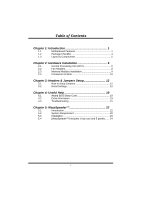
(CPU 6 2.2 Fan Headers 8 2.3 Memory Modules Installation 9 2.4 Connectors & Slots 10 Chapter 3: Headers & Jumpers Setup 12 3.1 How to setup Jumpers 12 3.2 Detail Settings 12 Chapter 4: Useful Help 19 4.1 Award BIOS Beep Code 19 4.2 Extra Information 19 4.3 Troubleshooting - Biostar NF4 4X-A7 | User Manual - Page 3
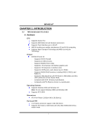
NF44X-A7 CHAPTER 1: INTRODUCTION 1.1 MOTHERBOARD FEATURES A. Hardware CPU Supports Socket 754. Supports AMD Athlon 64 and Sempron processors. Supports Front Side Bus up to 1.6G HT. AMD 64 architecture enables simultaneous 32 and 64 bit computing. Supports HyperTransport Technology and AMD Cool'n' - Biostar NF4 4X-A7 | User Manual - Page 4
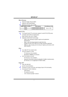
memory size is 2GB. DIMM Socket Location DDR Module Total Memory Size DIMM1 DIMM2 128MB/256MB/512MB/1GB *1 128MB/256MB/512MB/1GB *1 Max is 2 GB. Serial ATA 4 on-board Serial ATA connectors support 4 serial ATA (SATA) ports. Compliant with SATA1.0 specification. Data transfer rates up to - Biostar NF4 4X-A7 | User Manual - Page 5
NF44X-A7 On-board AC'97 Audio Sound Codec Chip: ALC655: - Compliant with AC'97 version2.3 specification. - Supports 6 channels audio output. 10/100 LAN Chip: RTL8201BL / RTL8201CL. Supports 10 Mb/s, 100 Mb/s and 1Gb/s auto-negotiation. Provides the most commonly used legacy super I/O functionality. - Biostar NF4 4X-A7 | User Manual - Page 6
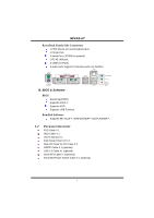
Center/ Left B. BIOS & Software BIOS Award legal BIOS. Supports APM1.2. Supports ACPI. Supports USB Function. Bundled Software Supports 9th Touch™, WINFLASHER™ and FLASHER™. 1.2 PACKAGE CHECKLIST FDD Cable X 1 HDD Cable X 1 User's Manual X 1 Fully Setup Driver CD X 1 Rear I/O Panel for ATX Case - Biostar NF4 4X-A7 | User Manual - Page 7
NF44X-A7 1.3 LAYOUT & COMPONENTS JKBMSV1 JKBMS1 JATXPWR2 JATXPWR1 JCFAN1 JCOM1 JPRNT1 Socket 754 JCOM2 (optional) CPU1 DIMM2 DIMM1 JUSB1 JUSBV1 JUSBLAN1 LAN JFAUDIO1 JAUDIO1 PEX16 Codec PEX1_1 JCDIN1 Super I/O BIOS PEX1_2 JSPDIF_OUT1 PCI1 PCI2 PCI3 JSFAN1 PCI4 BAT1 JNBFAN1 - Biostar NF4 4X-A7 | User Manual - Page 8
NF44X-A7 CHAPTER 2: HARDWARE INSTALLATION 2.1 CENTRAL PROCESSING UNIT (CPU) Step 1: Pull the lever sideways away from the socket and then raise the lever up to a 90-degree angle. Step 2: Look for the black cut edge on socket, and the white dot on CPU should point forwards this black cut edge. The - Biostar NF4 4X-A7 | User Manual - Page 9
NF44X-A7 Step 3: Hold the CPU down firmly, and then close the lever to complete the installation. Step 4: Put the CPU Fan on the CPU and buckle it. Connect the CPU FAN power cable to the JCFAN1. This completes the installation. 7 - Biostar NF4 4X-A7 | User Manual - Page 10
NF44X-A7 2.2 FAN HEADERS CPU FAN Power Header: JCFAN1 System Fan Power Header: JSFAN1 Northbridge Fan Power Header: JNBFAN1 JCFAN1 13 JNBFAN1 Pin Assignment 1 Ground 2 +12V 3 FAN RPM rate sense (Only for JCFAN1 and JSFAN1.) 31 JSFAN1 3 1 Note: The JCFAN1 and JSFAN1 support system cooling fan - Biostar NF4 4X-A7 | User Manual - Page 11
DIMM2 DIMM1 NF44X-A7 2.3 MEMORY MODULES INSTALLATION 2.3.1 DDR Module installation 1. Unlock a DIMM slot by pressing the retaining clips outward. Align a DIMM on the slot such that the notch on - Biostar NF4 4X-A7 | User Manual - Page 12
NF44X-A7 2.4 CONNECTORS & SLOTS Floppy Disk Connector: FDD1 The motherboard provides a standard floppy disk connector that supports 360K, 720K, 1.2M, 1.44M and 2.88M floppy disk types. This connector supports the provided floppy drive ribbon cables. 2 34 1 33 Hard Disk Connectors: IDE1/IDE2 The - Biostar NF4 4X-A7 | User Manual - Page 13
NF44X-A7 Peripheral Component Interconnect Slots: PCI1~PCI4 This motherboard is equipped with 4 standard PCI slot. PCI stands for Peripheral Component Interconnect, and it is a bus standard for expansion cards. This PCI slot is designated - Biostar NF4 4X-A7 | User Manual - Page 14
NF44X-A7 CHAPTER 3: HEADERS & JUMPERS SETUP 3.1 HOW TO SETUP JUMPERS The illustration shows how to set up jumpers. When the jumper cap is placed on pins, the jumper is "close", if not, that means the jumper is "open". Pin opened 3.2 DETAIL SETTINGS Pin closed Pin1-2 closed ATX Power Source - Biostar NF4 4X-A7 | User Manual - Page 15
NF44X-A7 ATX Power Source Connector: JATXPWR2 By connecting this connector, it will provide +12V to CPU power circuit. 4 3 12 Pin Assignment 1 1-2 Close 3 13 1 JUSBV2 Pin 2-3 Close 13 Note: In order to support this function "Power-on system via USB device," "JUSBV1/JUSBV2" jumper cap should be - Biostar NF4 4X-A7 | User Manual - Page 16
1-2 close 13 Pin 2-3 close Note: In order to support this function "Power-on system via keyboard and mouse", "JKBMSV1" jumper cap should be placed on Pin 2-3. Front Panel Audio-out Header: JFAUDIO1 This connector will allow user to connect with the front audio out put headers on the PC case. It - Biostar NF4 4X-A7 | User Manual - Page 17
NF44X-A7 CD-ROM Audio-in Connector: JCDIN1 This connector allows user to connect the audio source from the variety devices, like CD-ROM, DVD-ROM, PCI sound card, PCI TV turner card etc.. Pin Assignment 1 Left channel input 2 Ground 3 Ground 4 Right channel input 4 1 Case Open Headers: JCI1 This - Biostar NF4 4X-A7 | User Manual - Page 18
NF44X-A7 Digital Audio-out Connector: JSPDIF_OUT1 These connectors allow user to connect the PCI bracket SPDIF output or input header. Pin Assignment 1 +5V 2 SPDIF OUT 3 Ground 3 1 Headers for USB Ports at Front Panel: JUSB2~JUSB4 This connector allows user to connect additional USB cables at PC - Biostar NF4 4X-A7 | User Manual - Page 19
NF44X-A7 Serial ATA Connectors: JSATA1~JSATA4 The motherboard has a SATA Controller in nForce4 4X SLI with 4 channels SATA interface, it satisfies the SATA 1.0 spec user to restore the BIOS safe setting and the CMOS data, please carefully follow the procedures to avoid damaging the motherboard. - Biostar NF4 4X-A7 | User Manual - Page 20
NF44X-A7 JPANEL1: Header for Front Panel Facilities This 24-pin connector includes Power-on, Reset, HDD LED, Power LED, Sleep button, speaker and IrDA Connection. It allows user to connect the PC case's front panel switch functions. optional 24 23 Pin Assignment 1 +5V 3 N/A 5 N/A 7 Speaker 9 - Biostar NF4 4X-A7 | User Manual - Page 21
NF44X-A7 CHAPTER 4: USEFUL HELP 4.1 AWARD BIOS BEEP CODE Beep Sound Meaning One long beep followed by two short Video card not found or video card beeps memory bad High-low siren sound CPU overheated System will shut down automatically One Short beep when system boot-up No error found - Biostar NF4 4X-A7 | User Manual - Page 22
NF44X-A7 B. CPU Overheated If the system shutdown automatically after power on system for seconds, that means the CPU protection function has been activated. When the CPU is over heated, the motherboard will shutdown automatically to avoid a damage of the CPU, and the system may not power on again. - Biostar NF4 4X-A7 | User Manual - Page 23
NF44X-A7 4.3 TROUBLESHOOTING Probable Solution 1. No power to the system at all 1. Make sure power cable is securely Power light don't illuminate, fan plugged in. inside power supply does not 2. Replace cable. turn on. 3. Contact technical support "CMOS Failure." Review system's equipment. - Biostar NF4 4X-A7 | User Manual - Page 24
, in the About panel, you can get detail descriptions about BIOS model and chipsets. In addition, the frequency status of CPU, memory, AGP and PCI along with the CPU speed are synchronically shown on our main panel. Moreover, to protect users' computer systems if the setting is not appropriate when - Biostar NF4 4X-A7 | User Manual - Page 25
NF44X-A7 5.3 1. INSTALLATION Execute the setup execution file, and then the following dialog will pop up. Please click "Next" "Finish" button. Usage: The following figures are just only for reference, the screen printed in this user manual will change according to your motherboard on hand. 23 - Biostar NF4 4X-A7 | User Manual - Page 26
NF44X-A7 5.4 [WARPSPEEDER™] INCLUDES 1 TRAY ICON AND 5 PANELS 1. Tray Icon: Whenever the Tray Icon utility is launched, it will display a little tray icon on the right side - Biostar NF4 4X-A7 | User Manual - Page 27
NF44X-A7 2. Main Panel If you click the tray icon, [WarpSpeeder™] utility will be invoked. Please refer to the following figure; the utility's first window you will see is Main Panel. Main Panel contains features as follows: a. Display the CPU Speed, CPU external clock, Memory clock, AGP clock, and - Biostar NF4 4X-A7 | User Manual - Page 28
NF44X-A7 3. Voltage Panel Click the Voltage button in Main Panel, the button will be highlighted and the Voltage Panel will slide out to up as the following figure. In this panel, you can decide to increase CPU core voltage and Memory voltage or not. The default setting is "No". If you want to - Biostar NF4 4X-A7 | User Manual - Page 29
NF44X-A7 4. Overclock Panel Click the Overclock button in Main Panel, the button "-1MHz button", "+1MHz button", and "+3MHz button": provide user the ability to do real-time overclock adjustment. Warning: Manually overclock is potentially dangerous, especially when the overclocking percentage is over - Biostar NF4 4X-A7 | User Manual - Page 30
NF44X-A7 c. "Auto-overclock button": User can click this button and [WarpSpeeder™] will set the best verified best and stable frequency according to the Recovery Dialog's setting. d. "Verify button": User can click this button and [WarpSpeeder™] will proceed a testing for current frequency. If the - Biostar NF4 4X-A7 | User Manual - Page 31
NF44X-A7 6. About Panel Click the "about" button in Main Panel, the button will be highlighted and the About Panel will slide out to up as the following figure. In this panel, you can get model name and detail information in hints of all the chipset that are related to overclocking. You can also - Biostar NF4 4X-A7 | User Manual - Page 32
NF44X-A7 Note: Because the overclock, overvoltage, and hardware monitor features are controlled by several separate chipset, [WarpSpeeder™] divide these features to separate panels. If one chipset is not on board, the correlative button in Main panel will be disabled, but will not interfere other
-
 1
1 -
 2
2 -
 3
3 -
 4
4 -
 5
5 -
 6
6 -
 7
7 -
8
-
9
-
10
-
11
-
12
-
13
-
14
-
15
-
16
-
17
-
18
-
19
-
20
-
21
-
22
-
23
-
24
-
25
-
26
-
27
-
28
-
29
-
30
-
31
-
32
 |
 |

NF44X-A7
i
FCC Information and Copyright
This equipment has been tested and found to comply with the limits of a Class
B digital device, pursuant to Part 15 of the FCC Rules. These limits are designed
to provide reasonable protection against harmful interference in a residential
installation. This equipment generates, uses and can radiate radio frequency
energy and, if not installed and used in accordance with the instructions, may
cause harmful interference to radio communications. There is no guarantee
that interference will not occur in a particular installation.
The vendor makes no representations or warranties with respect to the
contents here and specially disclaims any implied warranties of merchantability
or fitness for any purpose. Further the vendor reserves the right to revise this
publication and to make changes to the contents here without obligation to
notify any party beforehand.
Duplication of this publication, in part or in whole, is not allowed without first
obtaining the vendor’s approval in writing.
The content of this user’s manual is subject to be changed without notice and
we will not be responsible for any mistakes found in this user’s manual. All the
brand and product names are trademarks of their respective companies.