Biostar P4M80-M4 P4M80-M4 user's manual
Biostar P4M80-M4 Manual
 |
View all Biostar P4M80-M4 manuals
Add to My Manuals
Save this manual to your list of manuals |
Biostar P4M80-M4 manual content summary:
- Biostar P4M80-M4 | P4M80-M4 user's manual - Page 1
P4M80-M4 FCC Information and and, if not installed and used in accordance with the instructions, may cause harmful interference to radio communications. There is approval in writing. The content of this user's manual is subject to be changed without notice and we will not be responsible for - Biostar P4M80-M4 | P4M80-M4 user's manual - Page 2
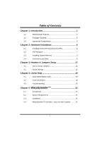
(CPU 6 2.2 FAN Headers 7 2.3 Installing System Memory 8 2.4 Connectors and Slots 9 Chapter 3: Headers & Jumpers Setup 12 3.1 How to Setup Jumpers 12 3.2 Detail Settings 12 Chapter 4: Useful Help 18 4.1 Award BIOS Beep Code 18 4.2 Extra Information 18 4.3 Troubleshooting - Biostar P4M80-M4 | P4M80-M4 user's manual - Page 3
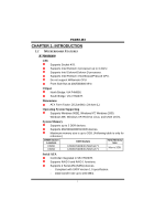
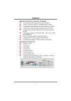
1.1 MOTHERBOARD FEATURES A. Hardware CPU Supports Socket 478. Supports Intel Pentium 4 processor up to 3.4GHz. Supports Intel Celeron/Celeron D processor. Supports Intel Pentium 4 Northwood/Prescott CPU. Do not support Williamate CPU. Front Side Bus at 400/533/800 MHz. Chipset North Bridge: VIA - Biostar P4M80-M4 | P4M80-M4 user's manual - Page 4
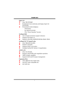
P4M80-M4 Super I/O Chip: ITE IT8705AF. Provides the most commonly used legacy Super I/O functionality. Environment Control initiatives: H/W Monitor Fan Speed Controller ITE's "Smart Guardian" function On Board IDE Two on-board connectors support 4 devices. Supports PIO Mode 0~4. Supports Ultra - Biostar P4M80-M4 | P4M80-M4 user's manual - Page 5
P4M80-M4 Internal On-board I/O Connectors and Headers 1 front panel header supports front panel facilities. 1 CD-in connector supports 1 CD-ROM audio-in device. 1 front audio header supports front panel audio-out function. 1 SPDIF-out connector supports digital audio-out function. 1 chassis open - Biostar P4M80-M4 | P4M80-M4 user's manual - Page 6
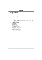
P4M80-M4 B. BIOS & Software BIOS Award legal BIOS. Supports APM1.2. Supports ACPI Supports USB Function. Software Supports Warpspeeder™, 9th Touch™, WINFLASHER™ and FLASHER™. 1.2 PACKAGE CHECKLIST FDD Cable X 1 HDD Cable X 1 User's Manual X 1 Fully Setup Driver CD X 1 USB 2.0 Cable X1 (optional) - Biostar P4M80-M4 | P4M80-M4 user's manual - Page 7
JATXPWR1 P4M80-M4 1.3 LAYOUT AND COMPONENTS JKBMS1 PU Socket 478 JCOM1 CPU1 JCFAN1 JPRNT JVGA1 DIMM1 DIMM2 JUSB1 JATXPWR2 IDE1 IDE2 JUSBLAN1 JAUDIO Super I/O BIOS P4M800 AGP1 LAN JAUDIO1 JCDIN1 JAUX1 (optional) Codec PCI1 JSPDIFO1 CNR1 PCI2 PCI3 JUSB3 JUSB4 BAT1 VT8237R JSATA2 - Biostar P4M80-M4 | P4M80-M4 user's manual - Page 8
P4M80-M4 CHAPTER 2: HARDWARE INSTALLATION 2.1 INSTALLING CENTRAL PROCESSING UNIT (CPU) PU PU Step 1: Pull the lever sideways away from the socket and then raise the lever up to a 90-degree angle. Step 2: Look for the white dot/cut edge. The white dot/cut edge should point - Biostar P4M80-M4 | P4M80-M4 user's manual - Page 9
P4M80-M4 2.2 FAN HEADERS These fan headers support cooling-fans built in the computer. The fan cable and connector may be different according to the fan manufacturer. Connect the fan cable to the connector while matching the black wire to pin#1. JCFAN1: CPU Fan Header JSFAN1: System Fan Header PU - Biostar P4M80-M4 | P4M80-M4 user's manual - Page 10
DIMM1 DIMM2 P4M80-M4 2.3 INSTALLING SYSTEM MEMORY PU 1. Unlock a DIMM slot by pressing the retaining clips outward. Align a DIMM on the slot such that the notch on the DIMM matches the break - Biostar P4M80-M4 | P4M80-M4 user's manual - Page 11
P4M80-M4 2.4 CONNECTORS AND SLOTS FDD1: Floppy Disk Connector The motherboard provides a standard floppy disk connector that supports 360K, 720K, 1.2M, 1.44M and 2.88M floppy disk types. This connector supports the provided floppy drive ribbon cables. PU 2 34 1 33 IDE1/IDE2: Hard Disk - Biostar P4M80-M4 | P4M80-M4 user's manual - Page 12
Component Interconnect, and it is a bus standard for expansion cards. This PCI slot is designated as 32 bits. PU PCI1 PCI2 PCI3 AGP1: Accelerated Graphics Port Slot Your monitor will attach directly to that video card. This motherboard supports video cards for PCI slots, but it is also equipped with - Biostar P4M80-M4 | P4M80-M4 user's manual - Page 13
P4M80-M4 CNR1: Communication Network Riser Slot The CNR specification is an open Industry Standard Architecture, and it defines a hardware scalable riser card interface, which supports modem only. PU 11 - Biostar P4M80-M4 | P4M80-M4 user's manual - Page 14
P4M80-M4 CHAPTER 3: HEADERS & JUMPERS SETUP 3.1 HOW TO SETUP JUMPERS The illustration shows how to set up jumpers. When the jumper cap is placed on pins, the - Biostar P4M80-M4 | P4M80-M4 user's manual - Page 15
P4M80-M4 JATXPWR2: ATX Power Connector By connecting this connector, it will provide +12V to CPU power circuit. PU Pin Assignment 1 +12V 3 4 2 +12V 1 2 3 Ground 4 Ground JAUDIO1: Front Panel Audio Header This header allows user to connect the front audio output cable with the PC - Biostar P4M80-M4 | P4M80-M4 user's manual - Page 16
P4M80-M4 JSPDIFO1: Digital Audio-out Connector This connector allows user to connect the PCI bracket SPDIF output header. PU Pin Assignment 1 +5V 2 SPDIF_OUT 3 Ground 3 1 JPANEL1: Front Panel Header This - Biostar P4M80-M4 | P4M80-M4 user's manual - Page 17
P4M80-M4 JUSB3/JUSB4: Front USB Headers This motherboard provides 2 USB 2.0 headers, which allows user to connect additional USB cable on the PC front panel, and also can be connected with internal USB devices, like USB card reader. PU Pin Assignment 1 +5V (fused) 2 +5V (fused) 3 USB- 4 USB- - Biostar P4M80-M4 | P4M80-M4 user's manual - Page 18
P4M80-M4 JSATA1/JSATA2: Serial ATA Connectors The motherboard has a PCI to SATA Controller with 2 channels SATA interface, it satisfies the SATA 1.0 spec and with transfer rate of 1.5Gb/s. PU JSATA2 7 41 1 47 JSATA1 Pin Assignment 1 Ground 2 TX+ 3 TX- 4 Ground 5 RX- 6 RX+ 7 Ground - Biostar P4M80-M4 | P4M80-M4 user's manual - Page 19
P4M80-M4 JCI1: Chassis Open Header This connector allows system to monitor PC case open status. If the signal has been triggered, it will record to the CMOS and show the message on next boot-up. PU Pin Assignment 1 Case open signal 2 Ground 12 17 - Biostar P4M80-M4 | P4M80-M4 user's manual - Page 20
P4M80-M4 CHAPTER 4: USEFUL HELP 4.1 AWARD BIOS BEEP CODE Beep Sound One long beep followed by two short beeps High-low siren sound One Short beep when system boot-up Long beeps every other second Meaning Video card not found or video card memory bad CPU overheated System will shut down - Biostar P4M80-M4 | P4M80-M4 user's manual - Page 21
P4M80-M4 B. CPU Overheated If the system shutdown automatically after power on system for seconds, that means the CPU protection function has been activated. When the CPU is over heated, the motherboard will shutdown automatically to avoid a damage of the CPU, and the system may not power on again. - Biostar P4M80-M4 | P4M80-M4 user's manual - Page 22
P4M80-M4 4.3 TROUBLESHOOTING Probable Solution 1. No power to the system at all 1. Make sure power cable is Power light don't illuminate, fan securely plugged in. inside power supply does not turn 2. Replace cable. on. 3. Contact technical support "CMOS Failure." Review system's equipment. - Biostar P4M80-M4 | P4M80-M4 user's manual - Page 23
P4M80-M4 about BIOS model and chipsets. In addition, the frequency status of CPU, memory, AGP and PCI along with the CPU speed Support: Windows 98 SE, Windows Me, Windows 2000, Windows XP DirectX: DirectX 8.1 or above. (The Windows XP operating system includes DirectX 8.1. If you use Windows XP - Biostar P4M80-M4 | P4M80-M4 user's manual - Page 24
P4M80-M4 5.3 INSTALLATION 1. Execute the setup execution file, and then the following dialog will pop up. Please click "Next" button "Finish" button. Usage: The following figures are just only for reference, the screen printed in this user manual will change according to your motherboard on hand. 22 - Biostar P4M80-M4 | P4M80-M4 user's manual - Page 25
P4M80-M4 5.4 [WARPSPEEDER™] INCLUDES 1 TRAY ICON AND 5 PANELS 1. Tray Icon: Whenever the Tray Icon utility is launched, it will display a little tray icon on the right side of Windows Taskbar. This utility is responsible for conveniently invoking [WarpSpeeder™] Utility. You can use the mouse by - Biostar P4M80-M4 | P4M80-M4 user's manual - Page 26
P4M80-M4 2. Main Panel If you click the tray icon, [WarpSpeeder™] utility will be invoked. Please refer to the following figure; the utility's first window you will see is Main Panel. Main Panel contains features as follows: a. Display the CPU Speed, CPU external clock, Memory clock, AGP clock, and - Biostar P4M80-M4 | P4M80-M4 user's manual - Page 27
P4M80-M4 3. Voltage Panel Click the Voltage button in Main Panel, the button will be highlighted and the Voltage Panel will slide out to up as the following figure. In this panel, you can decide to increase CPU core voltage and Memory voltage or not. The default setting is "No". If you want to get - Biostar P4M80-M4 | P4M80-M4 user's manual - Page 28
P4M80-M4 4. Overclock Panel Click the Overclock button in Main Panel, the button and "+3MHz button": provide user the ability to do real-time overclock adjustment. Warning: Manually overclock is potentially dangerous, especially when the overclocking percentage is over 110 %. We strongly recommend - Biostar P4M80-M4 | P4M80-M4 user's manual - Page 29
P4M80-M4 c. "Auto-overclock button": User can click this button and [WarpSpeeder™] will set the best and DirectShow tests, the DirectX 8.1 or newer runtime library is required. And please make sure your display card's color depth is High color (16 bit) or True color( 24/32 bit ) that is required - Biostar P4M80-M4 | P4M80-M4 user's manual - Page 30
P4M80-M4 6. About Panel Click the "about" button in Main Panel, the button will be highlighted and the About Panel will slide out to up as the following figure. In this panel, you can get model name and detail information in hints of all the chipset that are related to overclocking. You can also - Biostar P4M80-M4 | P4M80-M4 user's manual - Page 31
P4M80-M4 Note: Because the overclock, overvoltage, and hardware monitor features are controlled by several separate chipset, [WarpSpeeder™] divide these features to separate panels. If one chipset is not on board, the correlative button in Main panel will be disabled, but will not interfere other
-
 1
1 -
 2
2 -
 3
3 -
 4
4 -
 5
5 -
 6
6 -
 7
7 -
8
-
9
-
10
-
11
-
12
-
13
-
14
-
15
-
16
-
17
-
18
-
19
-
20
-
21
-
22
-
23
-
24
-
25
-
26
-
27
-
28
-
29
-
30
-
31
 |
 |

P4M80-M4
i
FCC Information and Copyright
This equipment has been tested and found to comply with the limits of a Class
B digital device, pursuant to Part 15 of the FCC Rules. These limits are designed
to provide reasonable protection against harmful interference in a residential
installation. This equipment generates, uses and can radiate radio frequency
energy and, if not installed and used in accordance with the instructions, may
cause harmful interference to radio communications. There is no guarantee
that interference will not occur in a particular installation.
The vendor makes no representations or warranties with respect to the
contents here and specially disclaims any implied warranties of merchantability
or fitness for any purpose. Further the vendor reserves the right to revise this
publication and to make changes to the contents here without obligation to
notify any party beforehand.
Duplication of this publication, in part or in whole, is not allowed without first
obtaining the vendor’s approval in writing.
The content of this user’s manual is subject to be changed without notice and
we will not be responsible for any mistakes found in this user’s manual. All the
brand and product names are trademarks of their respective companies.