Biostar P4SFA P4SFA user's manual
Biostar P4SFA Manual
 |
View all Biostar P4SFA manuals
Add to My Manuals
Save this manual to your list of manuals |
Biostar P4SFA manual content summary:
- Biostar P4SFA | P4SFA user's manual - Page 1
P4SFA FCC Statement and Copyright This energy and, if not installed and used in accordance with the instructions, may cause harmful interference to radio communications. There is no guarantee found in this user's manual. All the brand and product names are trademarks of their respective companies. i - Biostar P4SFA | P4SFA user's manual - Page 2
Ranuras 18 DEUTSCH 24 Merkmale des P4SFA ...24 Verpackungsinhalt...25 Layout von P4SFA (für Version 2.1 26 Layout von P4SFA (für Version 3.0 und danch 27 Installation der CPU...28 DDR-DIMM-Modules: DDR1-2 29 Jumpers, Headers, Connectors & Slots 30 TROUBLE SHOOTING 35 SOLUCIÓN DE PROBLEMAS 36 - Biostar P4SFA | P4SFA user's manual - Page 3
Duplex. - Auto Negotiation: 10/ 100, Full/ Half Duplex. Audio - AC97 2.2 interface. - PC99 complaint. - Supports 6 channels. On Board Peripherals - Supports 360K, 720K, 1.2MB, 1.44MB and 2.88MB floppy disk drivers. - Supports 1 serial port. - Supports 1 VGA port. - Supports 1 LAN port (optional). 1 - Biostar P4SFA | P4SFA user's manual - Page 4
port. (SPP/EPP/ECP mode) - Supports PS/2 mouse and PS/2 keyboard. - Supports 1 vertical audio port. - Supports 4 rear USB2.0 ports and 2 front USB2.0 ports. BIOS - AWARD legal Bios. - Supports APM1.2. - Supports ACPI. - Supports USB Function. Operating System - Offers the highest performance for - Biostar P4SFA | P4SFA user's manual - Page 5
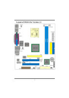
Layout of P4SFA for Version 2.1 JKBMS1 KB & Mouse JUSBV2 1 JUSB1 USB Socket 478 JCFAN1 1 JATXPWR2 JCOM1 JATXPWR1 COM1 JPRNT1 DDR1 DDR2 Parallel Port VGA1 ITE I/O JVGA1 BIOS USB & LAN 1 JUSBV3 JUSBLAN2 JAUDIO SIS 650 IDE2 IDE1 13 1 14 2 JAUDIO1 CODEC JGAME1 2 16 1 15 - Biostar P4SFA | P4SFA user's manual - Page 6
Layout of P4SFA for Version 3.0 and above JKBMS1 KB & Mouse JUSBV2 1 JUSB1 USB JCOM1 Socket 478 JCFAN1 1 JATXPWR2 JATXPWR1 COM1 JPRNT1 DDR1 DDR2 Parallel Port VGA1 ITE I/O JVGA1 BIOS USB & LAN 1 JUSBV3 JUSBLAN2 JAUDIO SIS 650 IDE2 IDE1 13 1 14 2 JAUDIO1 CODEC JGAME1 2 16 - Biostar P4SFA | P4SFA user's manual - Page 7
Pin A with the white dot/cut edge then insert the CPU. 3. Press the lever down. Then Put the fan on the CPU and buckle it and put the fan's power port into the JCFAN1, then to complete the installation. CPU/ System Fan Headers: JCFAN1/ JSFAN1 12V Sense Ground Sense 12V 1 1 Ground JSFAN1 - Biostar P4SFA | P4SFA user's manual - Page 8
DDR 200/266/Fuzzy 333 MHz Type required. DRAM Type: 64MB/ 128MB/ 256MB/ 512MB/ 1GB DIMM Module (184 pin) DIMM Socket Location DDR Module Total Memory Size (MB) DDR 1 64MB/128MB/256MB/512MB/1GB *1 Max is DDR 2 64MB/128MB/256MB/512MB/1GB 2GB *1 * The list shown above for DRAM configuration - Biostar P4SFA | P4SFA user's manual - Page 9
to that video card. This motherboard supports video cards for specification is an open Industry Standard Architecture and that defines a hardware scalable riser card interface, which supports audio and modem only. Peripheral Component Interconnect Slots: PCI1-2 (only for version 2.1) This motherboard - Biostar P4SFA | P4SFA user's manual - Page 10
Power Connectors: JATXPWR1/ JATXPWR2 JATXPWR2 (ATX 12V Power Connector) JATXPWR1 (ATX Main Power Connector) Wake On LAN Header: JWOL1 Front USB Header: JUSB2 Ground 5V_SB Wake up 1 JWOL1 2 1 JUSB2 Pin Assignment Pin Assignment 1 +5V 2 +5V 3 Data (-) 4 Data (-) 5 Data (+) 6 Data (+) 7 - Biostar P4SFA | P4SFA user's manual - Page 11
23 (+) (-) SPK RST IR HLED SPK ==> Speaker Conn. HLED ==> Hard Driver LED RST ==> Reset Button IR ==> Infrared Conn. SLP ==> Sleep Button PWR_LED ==> Power LED ON/ OFF ==> Power-on Button Audio Subsystem: JAUDIO1/ JCDIN1/ JCDIN2=> only for version 3.0 and above 1 JAUDIO1 2 (Front - Biostar P4SFA | P4SFA user's manual - Page 12
line out connector. 12 3 5 46 No jumpers 7 9 10 installed 11 12 13 14 Audio line out and mic in signals are available for front panel audio connectors. Digital Audio Connector: SPDIF_OUT1 SPDIF_OUT GND 5V Clear CMOS Jumper: JCMOS1 1 SPDIF_OUT1 JCMOS1 Assignment 1 Pin 1-2 on Normal - Biostar P4SFA | P4SFA user's manual - Page 13
1 No jumper installed 1 Pin 1-2 on Assignment Normal Operation (default) Case Open Back Panel Connectors JKBMS1 Mouse PS/2 JUSB1 Keyboard USB PS/2 JPRNT1 Parallel Port JUSBLAN2 LAN Line In Speaker Out MIC In COM1 JCOM1 VGA1 JVGA1 USB JAUDIO 11 - Biostar P4SFA | P4SFA user's manual - Page 14
Español Características del P4SFA CPU - Soporta procesador Intel Pentium 4® Socket 478 de hasta 2.8 GHz. - 100/ 133 Bus Modo Master. LAN - VT6103 (opcional) - Doble Velocidad - 100/10 Mbps. - Half y Full Duplex. - Auto Negociación: 10/ 100, Full/ Half Duplex. Audio - Interface AC97 2.2. - PC99 - Biostar P4SFA | P4SFA user's manual - Page 15
1 puerto de audio vertical. - Soporta 4 puertos USB2.0 traseros y 2 puertos USB2.0 frontales. BIOS - AWARD legal Bios. - Soporta APM1 del Paquete - Cable HDD X 1 - Cable FDD X 1 - Configuración Completa del CD Driver X 1 - Cable USB X 2 (Opcional) - Panel Trasero I/O para carcasa Micro-ATX X - Biostar P4SFA | P4SFA user's manual - Page 16
Disposición del P4SFA para Versión 2.1 JKBMS1 Teclado & Raton JUSBV2 1 JUSB1 USB JCOM1 Socket 478 JCFAN1 1 JATXPWR2 JATXPWR1 COM1 JPRNT1 DDR1 DDR2 Puerto Paralelo VGA1 ITE I/O JVGA1 BIOS USB & LAN 1 JUSBV3 JUSBLAN2 JAUDIO SIS 650 IDE2 IDE1 13 1 14 2 JAUDIO1 CODEC JGAME1 2 - Biostar P4SFA | P4SFA user's manual - Page 17
Disposición del P4SFA para Versión 3.0 en adelante JKBMS1 KB & Mouse JUSBV2 1 JUSB1 USB JCOM1 Socket 478 JCFAN1 1 JATXPWR2 JATXPWR1 COM1 JPRNT1 DDR1 DDR2 Parallel Port VGA1 ITE I/O JVGA1 BIOS USB & LAN 1 JUSBV3 JUSBLAN2 JAUDIO SIS 650 IDE2 IDE1 13 1 14 2 JAUDIO1 CODEC - Biostar P4SFA | P4SFA user's manual - Page 18
contacto A del zócalo y busque el punto blanco o corte el borde en la CPU. Empareje el contacto A con el punto blanco/ corte del borde, luego inserte la CPU. 3. Presione la palanca para abajo. Ponga el ventilador en la CPU y abróchelo. Luego ponga el puerto de corriente del ventilador en el JCFAN1 - Biostar P4SFA | P4SFA user's manual - Page 19
Módulos DDR DIMM: DDR1-2 DRAM Tiempo de Acceso: 2.5V Unbuffered DDR 200/266/Fuzzy 333 MHz Tipo requerido. DRAM Tipo: 64MB/ 128MB/ 256MB/ 512MB/ 1GB Módulo DIMM (184 contactos) Localización del Módulo DIMM Módulo DDR Total del Tamaño de Memoria (MB) DDR 1 64MB/128MB/256MB/512MB/1GB *1 Máximo - Biostar P4SFA | P4SFA user's manual - Page 20
. Ésta tarjeta AGP tomará ventaja de la tecnología del AGP para el mejoramiento de la eficiencia y funcionamiento del video, especialmente con gráficos 3D. Ranura Audio Módem Riser: AMR1 (solamente para versión 2.1) (solamente soporta tarjeta esclava) La especificación AMR es una industria estándar - Biostar P4SFA | P4SFA user's manual - Page 21
de Corriente: JATXPWR1/ JATXPWR2 JATXPWR2 (ATX 12V Conector de Corriente) JATXPWR1 (ATX Conector de Corriente Principal) Cabezal Wake On LAN: JWOL1 Tierra 5V_SB Wake up 1 Cabezal Frontal USB: JUSB2 JWOL1 2 1 JUSB2 Contactos Asignacion 1 +5V 3 Data (-) 5 Data (+) 7 Tierra 9 Key - Biostar P4SFA | P4SFA user's manual - Page 22
RST IR ==> LED del Disco Duro ==> Boton de Reinicio ==> Conector Infrarojo SLP ==> Boton de Suspension PWR_LED ==> Corriente LED ON/ OFF ==> Boton de Encendido Subsistema de Audio: JAUDIO1/ JCDIN1/ JCDIN2=> solamente para versión 3.0 en adelante 1 2 JAUDIO1 (Cabezal Frontal de - Biostar P4SFA | P4SFA user's manual - Page 23
22 1 14 13 JAUDIO1 Contactos 1 3 5 7 9 11 13 Asignacion Contactos Asignacion Entrada del MIC 2 Tierra Corriente del MIC 4 Corriente de Audio RT Salida de Linea 6 RT Salida de Linea Reservado 8 Key LFT Salida de Linea 10 LFT Salida de Linea RT Entrada de Linea 12 RT - Biostar P4SFA | P4SFA user's manual - Page 24
Conector Digital de Audio: SPDIF_OUT1 SPDIF_OUT GND 5V 1 SPDIF_OUT1 Puente de Borrar CMOS: JCMOS1 JCMOS1 Asignacion 1 Contacto 1-2 on Operacion Normal (Default) 1 Borrar Datos Contacto CMOS 2-3 on Cabezal de Juego: - Biostar P4SFA | P4SFA user's manual - Page 25
1 Puente sin instalar Operacion Normal (default) 1 Carcasa Abierta Contacto 1-2 on Conector del Panel Trasero JKBMS1 PS/2 Mouse JUSB1 PS/2 USB Keyboard JPRNT1 Puerto Paralelo JUSBLAN2 LAN Entrada de Linea Salida de Altavoz Entrada del MIC COM1 JCOM1 VGA1 JVGA1 USB JAUDIO 23 - Biostar P4SFA | P4SFA user's manual - Page 26
DMA 33/ 66/ 100/ 133 Bus Master Modus. LAN - VT6103 (optional) - Dual Speed - 100/10 Mbps. - Half- und Full-Duplex. - Auto Negotiation: 10/ 100, Full/ Half Duplex. Audio - AC97-2.2-Interface. - PC99 kompatibel. - Unterstützung für 6-Kanal. On-Board-Peripheriegeräte - 1 Floppy-Port mit Unterstützung - Biostar P4SFA | P4SFA user's manual - Page 27
LAN-Schnittstelle (optional). - 1 parallele Schnittstelle mit Unterstützung für SPP/EPP/ECP -Modus - Unterstützung für PS/2-Maus und PS/2 -Tastatur. - 1 vertikale Audio-Sschnittstelle. - 4 USB2.0-Ports auf der Rückwand und 2 USB2.0-Ports auf der Vorderseite. BIOS - Unterstützung für AWARD legal Bios - Biostar P4SFA | P4SFA user's manual - Page 28
P4SFA (für Version 2.1) JKBMS1 KB & Mouse JUSBV2 1 JUSB1 USB JCOM1 Sockel 478 JCFAN1 1 JATXPWR2 JATXPWR1 COM1 JPRNT1 DDR1 DDR2 Parallel Port VGA1 ITE I/O JVGA1 BIOS USB & LAN 1 JUSBV3 JUSBLAN2 JAUDIO SIS 650 IDE2 IDE1 13 1 14 2 JAUDIO1 CODEC JGAME1 2 16 1 15 AMR1 LAN - Biostar P4SFA | P4SFA user's manual - Page 29
Layout von P4SFA (für Version 3.0 und danch) JKBMS1 KB & Mouse JUSBV2 1 JUSB1 USB Sockel 478 JCFAN1 1 JATXPWR2 JCOM1 JATXPWR1 COM1 JPRNT1 DDR1 DDR2 Parallel Port VGA1 ITE I/O JVGA1 BIOS USB & LAN 1 JUSBV3 JUSBLAN2 JAUDIO SIS 650 IDE2 IDE1 13 1 14 2 JAUDIO1 CODEC JGAME1 2 - Biostar P4SFA | P4SFA user's manual - Page 30
Abschnittkante zusammen und legen Sie danach die CPU ein. 3. Drücken Sie den Hebel nach unten. Befestigen Sie danach den Lüfter auf die CPU und schließen Sie die Stromschnittstelle des Lüfters an JCFAN1 an und beenden Sie die Installation. CPU/ System Fan Headers: JCFAN1/ JSFAN1 12V Sensor Masse - Biostar P4SFA | P4SFA user's manual - Page 31
DDR-DIMM-Modules: DDR1-2 DRAM Zugriffszeit: 2.5V unbuffer DDR 200/266/ Fuzzy 333 MHz Typen erfordert. DRAM Typen: 64MB/ 128MB/ 256MB/ 512MB/ 1GB DIMM-Module (184 pin) DIMM- Sockel Standort DDR-Module Speichergröße (MB) DDR 1 64MB/128MB/256MB/512MB/1GB *1 maximal ist DDR 2 64MB/128MB/256MB/ - Biostar P4SFA | P4SFA user's manual - Page 32
Festplatte sollte immer an IDE1 angeschlossen werden. Diskettenanschluss: FDD1 Das Motherboard enthält einen standardmäßigen Diskettenanschluss, der 360K-, 720K-, zu verbessern, besonders wenn es sich um 3D-Grafiken handelt. Audio Modem Riser Slot: AMR1 (gilt nur Version 2.1) (unterstützt - Biostar P4SFA | P4SFA user's manual - Page 33
Stromversorgungsanschlüssü: JATXPWR1/ JATXPWR2 Wake On LAN Header: JWOL1 Front USB Header: JUSB2 Auswahl von 5V/ 5VSB fürUSB: JUSBV1/ JUSBV2JUSBV3 31 - Biostar P4SFA | P4SFA user's manual - Page 34
Anschlüsse auf der Vorderseite:JPANEL1 Audio Subsystem: JAUDIO1/ JCDIN1/ JCDIN2=> gilt für Version 3.0 und danch 32 - Biostar P4SFA | P4SFA user's manual - Page 35
Digital Audio Connector: SPDIF_OUT1 Jumper zum Löschen des CMOS: JCMOS1 33 - Biostar P4SFA | P4SFA user's manual - Page 36
Game Header: JGAME1 (Optional) Jumper zum Gehäuse-Öffnen: JCI1 Anschlüsse auf der Rückwand JKBMS1 Maus PS/2 JUSB1 Tastatur USB PS/2 JPRNT1 Parallel JUSBLAN2 LAN Line In Lautsprecher-Ausgang MIC In COM1 JCOM1 VGA1 JVGA1 USB JAUDIO 34 - Biostar P4SFA | P4SFA user's manual - Page 37
Trouble Shooting PROBABLE SOLUTION No power to the system at all Power light don't * Make sure power cable is securely plugged in illuminate, fan inside power supply does not turn on. Indicator light on keyboard does not turn on * Replace cable * Contact technical support controller board. - Biostar P4SFA | P4SFA user's manual - Page 38
Solución de Problemas CAUSA PROBABLE SOLUCIÓN No hay corriente en el sistema. La luz de * Asegúrese que el cable de transmisión esté corriente no ilumina, ventilador dentro de la seguramente enchufado. fuente de alimentación luz del teclado apagado. apagada. Indicador de * Reemplace el - Biostar P4SFA | P4SFA user's manual - Page 39
und Anwendungsdateien. Formatieren die Anwendungen sind funktionsfähig, aber es Sie die Festplatte und reinstallieren Sie die ist nicht möglich, das System von der Festplatte Anwendungen und Daten mit Hilfe von zu starten. Backup-Disks. MÖGLICHE URSACHE LÖSUNG Auf dem Bildschirm erscheint die - Biostar P4SFA | P4SFA user's manual - Page 40
04/4/2003 38
-
 1
1 -
 2
2 -
 3
3 -
 4
4 -
 5
5 -
 6
6 -
 7
7 -
8
-
9
-
10
-
11
-
12
-
13
-
14
-
15
-
16
-
17
-
18
-
19
-
20
-
21
-
22
-
23
-
24
-
25
-
26
-
27
-
28
-
29
-
30
-
31
-
32
-
33
-
34
-
35
-
36
-
37
-
38
-
39
-
40
 |
 |

P
P
4
4
S
S
F
F
A
A
i
FCC Statement and Copyright
This equipment has been tested and found to comply with the limits of a Class B
digital device, pursuant to Part 15 of the FCC Rules. These limits are designed to
provide reasonable protection against harmful interference in a residential
installation. This equipment generates, uses and can radiate radio frequency
energy and, if not installed and used in accordance with the instructions, may
cause harmful interference to radio communications. There is no guarantee that
interference will not occur in a particular installation.
The vendor makes no representations or warranties with respect to the contents
here of and specially disclaims any implied warranties of merchantability or
fitness for any purpose. Further the vendor reserves the right to revise this
publication and to make changes to the contents here of without obligation to
notify any party beforehand.
Duplication of this publication, in part or in whole is not allowed without first
obtaining the vendor’s approval in writing.
The content of this user’s is subject to be changed without notice and we will not
be responsible for any mistakes found in this user’s manual. All the brand and
product names are trademarks of their respective companies.