Biostar P4TDH Setup Manual
Biostar P4TDH Manual
 |
View all Biostar P4TDH manuals
Add to My Manuals
Save this manual to your list of manuals |
Biostar P4TDH manual content summary:
- Biostar P4TDH | Setup Manual - Page 1
radio frequency energy and, if not installed and used in accordance with the instructions, may cause harmful interference to radio communications. There is no guarantee that for any mistakes found in this user's manual. All the brand and product names are trademarks of their respective companies. i - Biostar P4TDH | Setup Manual - Page 2
...2 CPU Installation...3 DDR DIMM Modules: DDR1-3 4 Jumpers, Headers, Connectors & Slots 5 ESPAÑOL 11 Características del P4TDH 11 Contenido del Paquete ...12 Disposición del P4TDH...12 Instalación de la CPU ...13 Módulos DDR DIMM: DDR1-3 14 Conectores, Cabezales, Puentes y Ranuras 15 DEUTSCH - Biostar P4TDH | Setup Manual - Page 3
CCoonntteennttss TROUBLE SHOOTING 52 SOLUCIÓN DE PROBLEMAS 53 PROBLEMLÖSUNG 54 55 iii - Biostar P4TDH | Setup Manual - Page 4
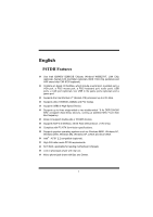
-sided or two double-sided * 8 for DDR 200/266 MHz unregister (Non-ECC) devices, running at 400/533 MHz Front Side Bus frequency. › Does not support double-side x 16 DDR devices. › Supports AGP 2.0 interface, 2X/4X Fast write protocol. (1.5V Only) › Complies with PC ATX form factor specifications - Biostar P4TDH | Setup Manual - Page 5
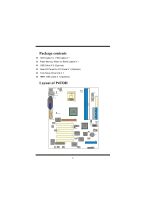
Package contents › HDD Cable X 1, FDD Cable X 1 › Flash Memory Writer for BIOS update X 1 › USB Cable X 2 (Optional) › Rear I/O Panel for ATX Case X 1 (Optional) › Fully Setup Driver CD X 1 › IEEE 1394 Cable X 1 (Optional) Layout of P4TDH K/B & Mouse JKBMS1 JKBV1 JATXPWR2 USB & LAN (Optional) - Biostar P4TDH | Setup Manual - Page 6
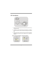
CPU Installation CPU 1. Pull the lever sideways away from the socket then raise the lever up to 90-degree angle. 2. Locate Pin A in the socket and lock for the white dot or cut edge in the CPU. Match Pin A with the white dot/cut edge then insert the CPU. 3. Press the lever down. Then Put the fan - Biostar P4TDH | Setup Manual - Page 7
/ 512MB DIMM Module (184 pin) Due to the limitation of chipset, this board only can support up to 2 banks of DDR memory. However, in the market, there are so many single-sided modules occuping half bank. BIOSTAR would like to utilize the modules as many as possible. So we divide one bank into - Biostar P4TDH | Setup Manual - Page 8
360K, 720K, 1.2M, 1.44M and 2.88M floppy disk types. This connector supports the provided floppy drive ribbon cables. Accelerated Graphics Port Slot: AGP1 Your monitor will attach directly to that video card. This motherboard supports video cards for PCI slots, but it is also equipped with an - Biostar P4TDH | Setup Manual - Page 9
==> 2.56V) PPPPJPPPPuiiiiiiiinnnnnnnnm13571357p--------o24682468pooooooooeffffnnnnnffff 222222222.........678956789VVVVVVVVV z It is for over voltage function. z Please set this header as "Open" while the voltage are adjusted via BIOS. Wake On LAN Header: WOL1 Ground 5V_SB Wake up 1 WOL1 6 - Biostar P4TDH | Setup Manual - Page 10
Front USB Header: JUSB3/ JUSB4 2 1 JUSB3/4 Pin1,2 ==> +5V Pin3,4 ==> Data(-) Pin5,6 ==> Data(+) Pin7,8 ==> Ground Pin9 ==> KEY Pin10 ==> NA 5V/ 5VSB Selection for USB: JUSBV1/ (JUSBV2/3_4=> Optional) 1 Pin 1-2 on ==> 5V JUSBV1/2/3_4 Pin 2-3 on ==> 5V_SB 5V/ 5VSB Selection for Keyboard: JKBV1 - Biostar P4TDH | Setup Manual - Page 11
Ground , Pin2 ==> MS1 Pin3 ==> 3.3V , Pin4 ==> MS2 Pin5 ==> MS3 , Pin6 ==> MS4 Pin7 ==> MS5 , Pin8 ==> MSCLK Pin9 ==> MSPWCTL# Pin10 ==> MSLED SD Memory Card Header: JSD1 (optional) 1 JSD1 Pin1 ==> Ground , Pin2 ==> SD1 Pin3 ==> 3.3V , Pin4 ==> SD2 Pin5 ==> SD3 , Pin6 ==> SD4 Pin7 ==> SD5 , Pin8 - Biostar P4TDH | Setup Manual - Page 12
Front Panel Connector: JPANEL1 SLP PWR_LED ON/OFF IR 2 24 1 23 SPK HLED RST IR SPK ==> Speaker Conn. HLED ==> Hard Driver LED RST ==> Reset Button IR ==> Infrared Conn. SLP ==> Sleep Button PWR_LED ==> Power LED ON/ OFF ==> Power-on Button Audio Subsystem: JAUDIO1/ JCDIN1 2 1 - Biostar P4TDH | Setup Manual - Page 13
Front Panel Audio Connector/ Jumper Block 12 Pin 5 and 6 Audio line out signals are routed 9 10 ==> to the back panel audio line out connector. Pin 9 and 10 12 Audio line out and mic in signals are available for front panel audio connectors. 9 10 Back Panel Connectors JKBMS1 RJ45USB1 PS/2 - Biostar P4TDH | Setup Manual - Page 14
Características del P4TDH › Usa Chipset que incluye un puerto en serie, un puerto paralelo, un puerto VGA, un puerto de ratón PS/2, un puerto de teclado PS/2, para dispositivos DDR 200/266 MHz unregister (sin-ECC), corriendo a 400/533 MHz frecuencia Front Side Bus. › No soporta dispositivos DDR de - Biostar P4TDH | Setup Manual - Page 15
› Cable HDD X 1, Cable FDD X 1 › Flash Memory Writer para actualización del BIOS X 1 › Cable USB X 2 (Opcional) › Panel trasero I/O para caja ATX X 1 (Opcional) › Configuración completa del Driver CD X 1 › Cable IEEE 1394 X1 (Opcional) Disposición del P4TDH JKBMS1 Teclado & Raton JKBV1 JATXPWR2 - Biostar P4TDH | Setup Manual - Page 16
Instalación de la CPU CPU 1. Tire de la palanca del lado del zócalo, luego levante la palanca hasta un ángulo de 90 grados. 2. Sitúe el contacto A del zócalo y busque el punto blanco o corte el borde en la CPU. Empareje el contacto A con el punto blanco/ corte del borde, luego inserte la CPU. 3. - Biostar P4TDH | Setup Manual - Page 17
soportar hasta 2 bancos de memoria DDR. Sin embargo, en el mercado existe cantidades de módulos de una cara ocupando la mitad de los bancos. BIOSTAR desea utilizar los módulos a la mayor cantidad posible. Es por ésta razon que dividimos un banco en 2 sockets. Ésto significa que un banco solamente - Biostar P4TDH | Setup Manual - Page 18
soporta 1.5V y 4X tarjeta AGP). Ésta tarjeta AGP tomará ventaja de la tecnología del AGP para el mejoramiento de la eficiencia y funcionamiento del video, especialmente con gráficos 3D. Ranura de la Banda de Suspensión de Comunicación y Red: CNR1 La especificación CNR es una abierta Industria de - Biostar P4TDH | Setup Manual - Page 19
=....>6789====VVVV====2>>>>.5V2222....6789VVVV z Para función de sobre voltaje. z Por favor configure el cabezal como "Abierto" mientras que el voltaje se ajustará por medio del BIOS. Cabezal Wake On LAN: WOL1 Tierra 5V_SB Wake up 1 WOL1 16 - Biostar P4TDH | Setup Manual - Page 20
Cabezal Frontal USB: JUSB3/ JUSB4 2 1 JUSB3/4 Pin1,2 ==> +5V Pin3,4 ==> Dato(-) Pin5,6 ==> Dato(+) Pin7,8 ==> Tierra Pin9 ==> KEY Pin10 ==> NA 5V/ 5VSB Selección para USB: JUSBV1/ (JUSBV2/3_4 => Opcional) 1 Contacto 1-2 encendido ==> 5V JUSBV1/2/3_4 Contacto 2-3 encendido ==> 5V_SB 5V/ 5VSB - Biostar P4TDH | Setup Manual - Page 21
Cabezal Memory Stick: JMS1 (opcional) 1 JMS1 Contacto1 ==> Tierra , Pin2 ==> MS1 Contacto3 ==> 3.3V , Contacto4 ==> MS2 Contacto5 ==> MS3 , Contacto6 ==> MS4 Contacto7 ==> MS5 , Contacto8 ==> MSCLK Contacto9 ==> MSPWCTL# Contacto10 ==> MSLED Cabezal - Biostar P4TDH | Setup Manual - Page 22
Conector del Panel Frontal: JPANEL1 SLP PWR_LED ON/OFF IR 2 24 1 23 SPK HLED RST IR SPK ==> Conector de Altavoz HLED ==> LED del Disco Duro RST ==> Boton de Reinicio IR ==> Conector Infrarojo SLP ==> Boton de Suspension PWR_LED ==> Corriente LED ON/ OFF ==> Boton de Encendido - Biostar P4TDH | Setup Manual - Page 23
Conector del Panel Frontal de Audio/ Jumper Block 12 Pin 5 y 6 La sen~al de salida de linea del Audio 9 10 Pin 9 y 10 ==> encamina al conector de la salida de linea del Audio ubicado en el panel trasero. 12 La se~nal de salida de linea del Audio y la sen~al de Entrada del Mic estan - Biostar P4TDH | Setup Manual - Page 24
P4TDH › Verwendet einen Intel 82845G/ 82801DB Chipsatz, Winbond W83627HF, LAN-Chip (optional), serieller ATA Controller (optional), IEEE 1394 Chip (optional) und H/W Sound-Chip CMI 8738 (optional). › Enthält Onboard I/O-Einrichtungen, wie z.B. serielle Schnittstelle, parallele Schnittstelle, VGA - Biostar P4TDH | Setup Manual - Page 25
› HDD-Kabel X 1, FDD-Kabel X 1 › Flash-Speicher-Writer für BIOS-Aktualisierung X 1 › USB-Kabel X 2 (Optional) › I/O-Rückseite für ATX-Gehäuse X 1 (Optional) › Installations-CD für Treiber X 1 › IEEE 1394-Kabel X 1 (Optional) Layout des P4TDH K/B & Maus JKBMS1 JKBV1 JATXPWR2 USB & LAN (Optional - Biostar P4TDH | Setup Manual - Page 26
Installation der CPU CPU 1. Ziehen Sie den Hebel seitwärts von der Sockel und neigen Sie ihn um 90-Grad nach oben. 2. Suchen Sie Pin A im Sockel und den weißen Punkt oder die Abschnittkante in der CPU. Passen Sie Pin A mit dem weißen Punkt/der Abschnittkante zusammen und legen Sie danach die CPU - Biostar P4TDH | Setup Manual - Page 27
Module (184 Pin) Aufgrund von Begrenzugen des Chipsatzes, unterstützt dieses Motherboard nur bis zu 2 Bänke von DDR-Speicher. Auf dem Markt gibt es jedoch viele einseitige Module die nur eine halbe Bank belegen. BIOSTAR möchte so viele Module wie möglich verwenden, daher wird eine Bank - Biostar P4TDH | Setup Manual - Page 28
ützt die mitgelieferte Bandkabel des Diskettenlaufwerks. Accelerated Graphics Port Slot: AGP1 Ihr Monitor wird direkt an die Grafikkarte angeschlossen. Dieses Motherboard unterstützt Grafikkarten für PCI-Slots, aber es ist auch mit einem Accelerated Graphics Port ausgestattet (AGP/ nur 1.5V und 4X - Biostar P4TDH | Setup Manual - Page 29
--------2468o2468feeeeoooofeiiiiffffnnnnffffn 222222222.....6789....56789VVVVVVVVV z Ist für die Überspannungsfunktion bestimmt. z Setzen Sie diesen Header auf "Offen" während die Spannung über das BIOS angepasst wird. Wake On LAN Header: WOL1 Masse 5V_SB Wake up 1 WOL1 26 - Biostar P4TDH | Setup Manual - Page 30
Front USB Header: JUSB3/ JUSB4 2 1 JUSB3/4 Pin1,2 ==> +5V Pin3,4 ==> Daten(-) Pin5,6 ==> Daten(+) Pin7,8 ==> Masse Pin9 ==> KEY Pin10 ==> nicht belegt 5V/ 5VSB Auswahl für USB: JUSBV1/ (JUSBV2/3_4=> Optional) 1 Pin 1-2 ein ==> 5V JUSBV1/2/3_4 Pin 2-3 ein ==> 5V_SB 5V/ 5VSB Auswahl für - Biostar P4TDH | Setup Manual - Page 31
Memory Stick Header: JMS1 (optional) 1 JMS1 Pin1 ==> Masse , Pin2 ==> MS1 Pin3 ==> 3.3V , Pin4 ==> MS2 Pin5 ==> MS3 , Pin6 ==> MS4 Pin7 ==> MS5 , Pin8 ==> MSCLK Pin9 ==> MSPWCTL# Pin10 ==> MSLED - Biostar P4TDH | Setup Manual - Page 32
Anschlüsse auf der Vorderseite: JPANEL1 SLP PWR_LED EIN/AUS IR 2 24 1 23 SPK HLED RST IR SPK ==> Lautsprecheranschl. HLED ==> Festplattenanzeige RST ==> Reset-Taste IR ==> Infrarotanschl. SLP ==> Sleep-Taste PWR_LED ==> Stromanzeige EIN/ AUS ==> Ein-/Ausschalttaste Audio - Biostar P4TDH | Setup Manual - Page 33
Audio-Anschluss auf Vorderseite/ Jumper-Block 12 Pin 5 and 6 Audio Line Out Signale werden an den ==> Audio Line Out Anschluss auf der 9 10 Pin 9 and 10 R kseite weitergeleitet. 12 Audio Line Out und Mikro In Signale sind f die Anschl se auf der Vorderseite verf bar. 9 10 Anschlüsse auf - Biostar P4TDH | Setup Manual - Page 34
日本語 P4TDH の機能 › Intel 82845G/ 82801DB Winbond W83627HF、LAN ATA IEEE 1394 H/W CMI 8738 VGAポート、PS/2 PS/2 USBポート、LAN 2つのUSB I/O › Intel Pentium 4 478 2.53 GHz Ultra 100/66/33、BMIDE、PIO USB2.0 DDR 200/266 MHz ECC 3つのシン 2 8 400/533 MHz x 16 DDR AGP 2.0 2X/4X 1.5Vのみ) › PC ATX - Biostar P4TDH | Setup Manual - Page 35
› HDD X 1、FDD X 1 › BIOS X 1 › USB X 2 ATX I/Oパネル X 1 CD X 1 › IEEE 1394 X 1 P4TDH JKBMS1 K /B と マウス JKBV1 JATXPWR2 USB と JUSBV1 AN JRJ45USB1 JCOM1 JPRNT1 JCFAN1 JATXPWR1 FDD1 COM1 DDR1 DDR2 DDR31 VGA1 JVGA1 JUSBV2 INTEL 82845G IDE2 IDE1 LINE-IN - Biostar P4TDH | Setup Manual - Page 36
CPU CPU 1 90 2 A CPU A CPU 3 CPU JCFAN1 CPU JCFAN1/ JSFAN1 12V 1 JCFAN1 1 設置 12V センス JSFAN1 33 - Biostar P4TDH | Setup Manual - Page 37
DDR DIMM DDR1-3 DRAM 2.5V ECC)DDR 200/266 MHz DRAMタイプ:64MB/ 128MB/ 256MB/ 512MB DIMM 184 2 DDR BIOSTAR 2 1 2 バンク DDR1 DDR2 DDR3 › Does not support Double-sided * 16 DDR Dimms 1には2つのDDR 1つが白、1 ※ 1つのDDR DDR DDR1 ※ 2つのDDR DDR DDR1と2 ※ DDR 3 DDR ※ DDR1/2では最高2 8 DDR - Biostar P4TDH | Setup Manual - Page 38
IDE1/ IDE2/ (IDE3 32 PCI IDE PIO モード0-4 Ultra DMA / 33 /66 / 100 IDE1 IDE2 IDE3 3つのHDD IDE 4 IDE1 ATA JSATA1/ JSATA2 2 S-ATA PCIからSATA SATA 1.0 5GH FDD1 360K、720K、 1.44M、2.88M AGP1 PCI AGP/1.5V及び4X AGP AGPカードはAGP 3D CNR1 CNR PCI1-5 5つの標準PCI - Biostar P4TDH | Setup Manual - Page 39
/ JATXPWR2 JATXPWR2 (A T X 12V JATXPWR1 (A T X M a in DIMM JDIMMVOLT 1 2 12 JDIMMVOLT (Default ==> 2.5V) Pin 1-2 off ==> 2.6V Pin 3-4 off ==> 2.7V Pin 5-6 off ==> 2.8V Pin 7-8 off ==> 2.9V z z 電圧がBIOS い。 LAN WOL1 接地 5V_SB 1 フロント WOL1 JUSB3/ JUSB4 USB 2 1 JUSB3/4 36 - Biostar P4TDH | Setup Manual - Page 40
USBの5V/ 5VSB選択:JUSBV1/ (JUSBV2/3_4 1 ピン1 - 2 5 V ピン2 - 3 5 V _S B JUSBV1/2/3_4 5V/ 5VSB 選択:JKBV1 1 JKBV1 ピン1 - 2 5 V ピン2 - 3 5 V _S B 1394 J1394A1/J1394B1/J1394C1 ピン1 ,2 2 1 ピン3 ,4 ピン5 ,6 ピン7 ,8 J1394A1/B1/C1 ピン9 ピン1 0 ==> A +/A B +/ B ==> +12V ==> KEY ==> N A JMS1 1 - Biostar P4TDH | Setup Manual - Page 41
SD JSD1 1 JSD1 ピン1 = = > G ro u n d , ピン2 = = > S D 1 ピン3 = = > 3 .3 V , ピン4 = = > S D 2 ピン5 = = > S D 3 ,ピン6 = = > S D 4 ピン7 = = > S D 5 ,ピン8 = = > S D C L K ピン9 = = > S D P W C T L # ピン1 0 = = > S D L E D JSC1 ピン1 = = > 5 V ,ピン2 ピン3 = = > S C A P W R C T L # ピン4 = = > S C A R 5 # - Biostar P4TDH | Setup Manual - Page 42
JAUDIO1/ JCDIN1 2 1 JAUDIO1 1 JCDIN1 (C D - R O M 39 - Biostar P4TDH | Setup Manual - Page 43
12 9 10 12 9 10 JKBMS1 RJ45USB1 P S / 2 L A N JPRNT1 JGAME1_USB1 P S /2 USB COM1 JCOM1 VGA1 JVGA1 JKBMS1 RJ45USB1 L A N JPRNT1 JGAME1_USB1 U S B P S /2 USB COM1 JCOM1 VGA1 JVGA1 (U S B 40 - Biostar P4TDH | Setup Manual - Page 44
speed as well as the chipset information. Also, in the About panel, you can get the detailed descriptions about BIOS model and chipsets. In addition, the frequency statuses of CPU, memory, AGP, and PCI along with the CPU speed are synchronically shown on our main panel. Moreover, to protect users - Biostar P4TDH | Setup Manual - Page 45
System Requirement OS Support: Windows 98 SE, Windows 98 Me, Windows 2000, Windows XP DirectX: DirectX 8.1 or above. (The Windows XP operating system includes DirectX 8.1. If you use Windows - Biostar P4TDH | Setup Manual - Page 46
2. When you see the following dialog in setup procedure, it means setup is completed. If the "Launch the WarpSpeeder Tray Utility" checkbox is checked, the Tray Icon utility and [ WarpSpeeder™ ] utility will be automatically and immediately launched after you click "Finish" button. 43 - Biostar P4TDH | Setup Manual - Page 47
Usage [ WarpSpeeder™ ] includes 1 tray icon and 5 panel: 1. Tray Icon: Whenever the Tray Icon utility is launched, it will display a little tray icon on the right side of Windows Taskbar. This utility is responsible for conveniently invoking [ WarpSpeeder™ ] Utility. You can use mouse to left-click - Biostar P4TDH | Setup Manual - Page 48
utility's first window you see is Main Panel. Main Panel contains features as follows: a. Display the CPU Speed, CPU external clock, Memory clock, AGP clock, and PCI clock information. b. Contains About, Voltage, Overclock, and Hardware Monitor Buttons for invoking respective panels. c. With a user - Biostar P4TDH | Setup Manual - Page 49
and the Voltage Panel will slide out to up as the following figure. In this panel, you can decide to increase CPU core voltage and Memory voltage or not. The default setting is "No". If you want to get the best performance of overclocking, we recommend you click the option "Yes - Biostar P4TDH | Setup Manual - Page 50
3MHz button", "-1MHz button", "+1MHz button", and "+3MHz button": provide user the ability to do real-time overclock adjustment. Warning: Manually overclock is potentially dangerous, especially when the overclocking percentage is over 110 %. We strongly recommend you verify every speed you overclock - Biostar P4TDH | Setup Manual - Page 51
Dialog's setting. d. "Verify button": User can click this button and [ WarpSpeeder™ ] will proceed a testing for current frequency. If the testing is ok, then the current frequency will be saved into system registry. If the testing fails, system will do a fail-safe rebooting. After reboot, the [ - Biostar P4TDH | Setup Manual - Page 52
panel, you can get model name and detailed information in hints of all the chipset that are related to overclocking. You can also get the mainboard's BIOS model and the Version number of [ WarpSpeeder™ ] utility. 49 - Biostar P4TDH | Setup Manual - Page 53
50 - Biostar P4TDH | Setup Manual - Page 54
Note: Because the overclock, overvoltage, and hardware monitor features are controlled by several separate chipset, [ WarpSpeeder™ ] divide these features to separate panels. If one chipset is not on board, the correlative button in Main panel will be disabled, but will not interfere other panels' - Biostar P4TDH | Setup Manual - Page 55
Trouble Shooting PROBABLE SOLUTION No power to the system at all Power light don't * Make sure power cable is securely plugged in illuminate, fan inside power supply does not on. Indicator light on keyboard does not turn turn on * Replace cable * Contact technical support PROBABLE - Biostar P4TDH | Setup Manual - Page 56
Solución de Problemas CAUSA PROBABLE SOLUCIÓN No hay corriente en el sistema. La luz de * Asegúrese que el cable de transmisión esté corriente no ilumina, ventilador dentro de la seguramente enchufado. fuente de alimentación apagada. luz del teclado apagado. Indicador de * Reemplace el cable - Biostar P4TDH | Setup Manual - Page 57
Problemlösung MÖGLICHE URSACHE LÖSUNG Das System hat keine Spannungsversorgung. * Versichern Sie sich, dass das Stromkabel richtig Die Stromanzeige leuchtet nicht, der Lüfter im angebracht ist Inneren der eingeschaltet. Stromversorgung Tastaturleuchten sind wird nicht nicht an. * Ersetzen - Biostar P4TDH | Setup Manual - Page 58
トラブル 解決方法 いない。 トラブル 解決方法 DIMM トラブル 解決方法 CD-ROM CMOS トラブル 解決方法 CD-ROM トラブル 解決方法 Invalid Configuration CMOS Failure トラブル 解決方法 55 - Biostar P4TDH | Setup Manual - Page 59
2 * SETUP 56 - Biostar P4TDH | Setup Manual - Page 60
07/22/2002 57
-
 1
1 -
 2
2 -
 3
3 -
 4
4 -
 5
5 -
 6
6 -
 7
7 -
8
-
9
-
10
-
11
-
12
-
13
-
14
-
15
-
16
-
17
-
18
-
19
-
20
-
21
-
22
-
23
-
24
-
25
-
26
-
27
-
28
-
29
-
30
-
31
-
32
-
33
-
34
-
35
-
36
-
37
-
38
-
39
-
40
-
41
-
42
-
43
-
44
-
45
-
46
-
47
-
48
-
49
-
50
-
51
-
52
-
53
-
54
-
55
-
56
-
57
-
58
-
59
-
60
 |
 |

P
P
4
4
T
T
D
D
H
H
H
i
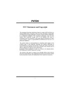
FCC Statement and Copyright
This equipment has been tested and found to comply with the limits of a
Class B digital device, pursuant to Part 15 of the FCC Rules. These limits
are designed to provide reasonable protection against harmful interference
in a residential installation. This equipment generates, uses and can
radiate radio frequency energy and, if not installed and used in
accordance with the instructions, may cause harmful interference to radio
communications. There is no guarantee that interference will not occur in a
particular installation.
The vendor makes no representations or warranties with respect to the
contents here of and specially disclaims any implied warranties of
merchantability or fitness for any purpose. Further the vendor reserves the
right to revise this publication and to make changes to the contents here of
without obligation to notify any party beforehand.
Duplication of this publication, in part or in whole is not allowed without
first obtaining the vendor’s approval in writing.
The content of this user’s is subject to be changed without notice and we
will not be responsible for any mistakes found in this user’s manual. All the
brand and product names are trademarks of their respective companies.