Biostar T5 XE Setup Manual
Biostar T5 XE Manual
 |
View all Biostar T5 XE manuals
Add to My Manuals
Save this manual to your list of manuals |
Biostar T5 XE manual content summary:
- Biostar T5 XE | Setup Manual - Page 1
T5 XE/T5XE CFX-SLI Setup Manual FCC Information and Copyright This equipment has been tested and found to comply with in a residential installation. This equipment generates, uses, and can radiate radio frequency energy and, if not installed and used in accordance with the instructions, may cause - Biostar T5 XE | Setup Manual - Page 2
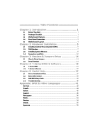
Jumpers 14 3.2 Detail Settings 14 Chapter 4: T-Series BIOS & Software 19 4.1 T-Series BIOS 19 4.2 T-Series Software 27 Chapter 5: Useful Help 27 5.1 Driver Installation Note 37 5.2 Extra Information 38 5.3 AMI BIOS Beep Code 39 5.4 Troubleshooting 40 Appendix: SPEC In Other Languages 41 - Biostar T5 XE | Setup Manual - Page 3
CHAPTER 1: INTRODUCTION T5 XE/T5XE CFX-SLI 1.1 BEFORE YOU START Thank you for choosing our product. Before you start installing the motherboard, please make sure you follow the instructions below: „ Prepare a dry and stable working environment with sufficient lighting. „ Always disconnect the - Biostar T5 XE | Setup Manual - Page 4
Motherboard Manual 1.3 MOTHERBOARD FEATURES SPEC Supports Execute Disable Bit / Enhanced Intel Socket 1156 CPU Intel Core i7 / i5 processor SpeedStep® / Intel Architecture-64 / Extended Memory 64 Technology / Virtualization Technology Chipset Intel P55 IT8720 Environment Control initiatives, - Biostar T5 XE | Setup Manual - Page 5
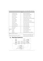
T5 XE/T5XE CFX-SLI SPEC Front Panel Connector x1 Supports front panel facilities Front Audio Connector x1 Supports front panel audio function CD-in Connector x1 Supports CD audio-in function S/PDIF out Connector x1 Supports digital audio out function CPU Fan Header x1 CPU Fan power - Biostar T5 XE | Setup Manual - Page 6
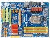
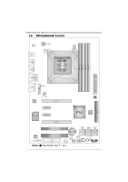
2 DDR3 _A 1 DDR3 _B 2 DDR3 _B 1 Motherboard Manual 1.5 MOTHERBOARD LAYOUT JUSBV1 KBMS1 USB2 USB1 ATXPWR2 VTT_D1 CPU_FAN1 Socket 1156 CPU1 RJ45USB1 AUDIO2 SPDIF1 CD_IN1 SYS_FAN2 LAN PEX16_1 ATXPWR1 BIOS IDE 1 Super I/O PEX1_1 PEX1_2 PEX16_2 P55 IDE PCI1 BAT1 SATA6 SATA5 SATA4 SATA3 - Biostar T5 XE | Setup Manual - Page 7
T5 XE/T5XE CFX-SLI CHAPTER 2: HARDWARE INSTALLATION 2.1 INSTALLING CENTRAL PROCESSING UNIT (CPU) Special Notice: Remove Pin Cap before installation, and make good preservation for future use. When the CPU is removed, cover the Pin Cap on the empty socket to ensure pin legs won't be damaged. Step 1: - Biostar T5 XE | Setup Manual - Page 8
Motherboard Manual Step 3: Look for the triangular cut edge on socket, and the golden dot on CPU should point forwards this triangular cut edge. The CPU will fit only in the correct orientation. Step 4: Hold the - Biostar T5 XE | Setup Manual - Page 9
T5 XE/T5XE CFX-SLI 2.2 FAN HEADERS These fan headers support cooling-fans built in the computer. The +12V 3 FAN RPM rate sense 13 SYS_FAN1 Note: The SYS_FAN1/SYS_FAN2 support 3-pin head connectors; the CPU_FAN1 supports 4-pin head connector. When connecting with wires onto connectors, please note - Biostar T5 XE | Setup Manual - Page 10
DDR3_A2 DDR3_A1 DDR3_B2 DDR3_B1 Motherboard Manual 2.3 INSTALLING SYSTEM MEMORY A. Memory Modules 1. Unlock a DIMM slot by pressing the retaining clips outward. Align a DIMM on the slot such that the notch on the DIMM matches the break - Biostar T5 XE | Setup Manual - Page 11
T5 XE/T5XE CFX-SLI B. Memory Capacity DIMM Socket Location DDR3 Module DDR3_A1 512MB/1GB/2GB/4GB DDR3_A2 512MB/1GB/2GB/4GB DDR3_B1 512MB/1GB/2GB/4GB DDR3_B2 512MB/1GB/2GB/4GB Total Memory Size Max is 16GB. C. Dual Channel Memory Installation Please refer to the following requirements to - Biostar T5 XE | Setup Manual - Page 12
360K, 720K, 1.2M, 1.44M and 2.88M floppy disk types. This connector supports the provided floppy drive ribbon cables. 2 34 1 33 IDE1: Hard Disk Connector The motherboard has a 32-bit Enhanced PCI IDE Controller that provides PIO Mode 0~4, Bus Master, and Ultra DMA 33/66/100/133 functionality - Biostar T5 XE | Setup Manual - Page 13
T5 XE/T5XE CFX-SLI SATA1~SATA6: Serial ATA Connectors The motherboard has a PCI to SATA Controller with 6 channels SATA interface, it satisfies the SATA 2.0 spec and with transfer rate of 3.0Gb/s. SATA6 SATA4 SATA2 SATA5 SATA3 SATA1 Pin - Biostar T5 XE | Setup Manual - Page 14
Motherboard Manual ATXPWR2: ATX Power Source Connector This connector provides +12V to CPU power circuit. 32 4 well plugged-in. PCI1/PCI2: Peripheral Component Interconnect Slots This motherboard is equipped with 2 standard PCI slots. PCI stands for Peripheral Component Interconnect, and it is a bus - Biostar T5 XE | Setup Manual - Page 15
T5 XE/T5XE CFX-SLI PEX16_1: PCI-Express Gen2 x16 (x16/CrossFireX x8, SLI x8 Speed) Slot - PCI-Express 2.0 compliant. - Maximum theoretical realized bandwidth of 8GB/s (4GB/s CrossFireX/SLI) simultaneously per direction, for an aggregate of 16GB/s(8GB/s CrossFireX/SLI) totally. - PEX16_1 & PEX16_2 - Biostar T5 XE | Setup Manual - Page 16
Motherboard Manual CHAPTER 3: HEADERS & JUMPERS SETUP 3.1 HOW TO SETUP JUMPERS The illustration shows how to set up jumpers. When the jumper cap is placed on pins, the - Biostar T5 XE | Setup Manual - Page 17
T5 XE/T5XE CFX-SLI F_USB1/F_USB2: Headers for USB 2.0 Ports at Front Panel These headers allow user to connect additional USB cable on the PC front panel, and also - Biostar T5 XE | Setup Manual - Page 18
Motherboard Manual F_AUDIO1: Front Panel Audio Header This header allows user to connect the allows user to connect the audio source from the variaty devices, like CD-ROM, DVD-ROM, PCI sound card, PCI TV turner card etc.. Pin Assignment 4 1 Left Channel Input 2 Ground 1 3 Ground 4 Right - Biostar T5 XE | Setup Manual - Page 19
T5 XE/T5XE CFX-SLI JCMOS1: Clear CMOS Header Placing the jumper on pin2-3 allows user to restore the BIOS safe setting and the CMOS data. Please carefully follow the procedures to avoid damaging the motherboard. 13 Pin 1-2 Close: Normal Operation (default). 13 13 Pin 2-3 Close: Clear CMOS data. - Biostar T5 XE | Setup Manual - Page 20
Motherboard Manual On-Board LED Indicators There are 8 LED indicators on the motherboard showing system status. PH4_D 4 PH3_D 3 PH2_D 2 PH1_D 1 VTT_ for specific messages: LED1 LED2 Message ON ON Normal ON OFF OFF Memory Error ON VGA Error OFF OFF Abnormal: CPU / Chipset error. PH1_D1 - Biostar T5 XE | Setup Manual - Page 21
T5 XE/T5XE CFX-SLI CHAPTER 4: T-SERIES BIOS & SOFTWARE 4.1 T-SERIES BIOS T-Series BIOS Features Overclocking Navigator Engine (O.N.E.) Memory Integration Test (M.I.T., under Overclock Navigator Engine) BIO-Flasher: Update BIOS file from USB Flash Drive or FDD Self Recovery System (S.R.S) Smart Fan - Biostar T5 XE | Setup Manual - Page 22
display after overclocking Over-Clocking Navigator [Manual OverClock] =========== Automate OverClock System =========== Auto OverClock System [V6-Tech Engine] Manual OverClock System Current CPU Frequency : Current Memory Frequency : Over Clock Retry Count [1] Intel(R) SpeedStep(tm - Biostar T5 XE | Setup Manual - Page 23
T5 XE/T5XE CFX-SLI DRAM Frequency To get better system performance, sometimes downgrading the memory frequency is necessary when > Clock Gen Configuration > Voltage Control > Intel PPM Configuration Options Normal Automate OverClock Manual OverClock Select Screen Select Item EnterGo to Sub Screen - Biostar T5 XE | Setup Manual - Page 24
. Over-Clocking Navigator [Automate OverClock] =========== Automate OverClock System =========== Auto OverClock System [V8-Tech Engine] Manual OverClock System Current CPU Frequency : Current Memory Frequency : Over Clock Retry Count [1] Intel(R) SpeedStep(tm) tech CPU Ratio - Biostar T5 XE | Setup Manual - Page 25
T5 XE/T5XE CFX-SLI Notices: Not all types of Intel CPU perform above overclock setting ideally; the difference will be based on the selected CPU model. B. Memory Integration Test (M.I.T.) This function is under "Overclocking Navigator Engine" item. MIT allows users to test memory compatibilities, - Biostar T5 XE | Setup Manual - Page 26
Motherboard Manual C. BIO-Flasher BIO-Flasher is a BIOS flashing utility providing you an easy and simple way to update your BIOS via USB pen drive or floppy disk. The BIO-Flasher is built in the BIOS chip. To enter the utility, press during the Power-On Self Tests (POST) procedure while - Biostar T5 XE | Setup Manual - Page 27
T5 XE/T5XE CFX-SLI D. Self Recovery System (S.R.S.) This function can't be seen under BIOS setup; and is always on whenever the system starts up. However, it can prevent system hang-up due to inappropriate overclock actions. When the system hangs up, S.R.S. will automatically log in the default BIOS - Biostar T5 XE | Setup Manual - Page 28
Motherboard Manual Smart Fan Calibration Choose this item and then the BIOS will automatically test and detect the BIOS-ROM. Users are able to reload any saved CMOS setting for customizing system configurations. Moreover, users are able to save an ideal overclock setting during overclock operation - Biostar T5 XE | Setup Manual - Page 29
XE/T5XE CFX-SLI Installing T-Series Software 1. Insert the Setup CD to the optical drive. The drivers installation program would appear if the Auto-run function has been enabled. 2. Select Software Installation, and then click on the respective software title. 3. Follow the on-screen instructions - Biostar T5 XE | Setup Manual - Page 30
Motherboard Manual The CPU tab provides information on the CPU and motherboard. The Memory tab provides information on the memory module(s). You can select memory module on a specific slot to see its information. The OC Tweaker tab allows you to change system clock settings and voltages settings. It - Biostar T5 XE | Setup Manual - Page 31
T5 XE/T5XE CFX-SLI The HW Monitor tab allows you to monitor hardware voltage, fan speed, and temperature. Besides, you also can set related values for CPU Smart Fan. The About tab provides information about manufacturer and software version. You can update new version by clicking the button "Live - Biostar T5 XE | Setup Manual - Page 32
Motherboard Manual Green Power Utility BIOSTAR G.P.U (Green Power Utility) is a new function. The utility enhances energy efficiency by disabling extra phases while CPU is on light loading. It integrates a friendly GUI - Biostar T5 XE | Setup Manual - Page 33
T5 XE/T5XE CFX-SLI G.P.U Mode Setting This utility provides five modes, upon your requirements, to improve system performance or to save power consumption. Note: Even if the modes saving - Biostar T5 XE | Setup Manual - Page 34
Motherboard Manual eHot-Line (Optional) eHot-Line is a convenient utility that helps you to contact with our Tech-Support system. This utility will collect the system information which is useful for analyzing the problem you may have encountered, and then send these information to our tech-support - Biostar T5 XE | Setup Manual - Page 35
the file name and then click "Save". Your system information will be saved to a .txt file. T5 XE/T5XE CFX-SLI Open the saved .txt file, you will see your system information including motherboard/BIOS/CPU/video/ device/OS information. This information is also concluded in the sent mail. We will not - Biostar T5 XE | Setup Manual - Page 36
Motherboard Manual BIOS Update BIOS Update is a convenient utility which allows you to update your motherboard BIOS under Windows system. AWARD BIOS Show current BIOS information AMI BIOS Clear CMOS function (Only for AWARD BIOS) Save current BIOS to a .bin file Update BIOS - Biostar T5 XE | Setup Manual - Page 37
T5 XE/T5XE CFX-SLI Before doing this, please download the proper BIOS file from the website. For AWARD BIOS, update BIOS procedure should be run with Clear CMOS function, so please check on Clear CMOS first. Then click Update BIOS button, a dialog will show for asking you backup - Biostar T5 XE | Setup Manual - Page 38
BMP as your boot logo so as to customize your computer. Please follow the following instruction to update boot logo: 1. Load Image:Choose the picture as the boot logo. 2. Transform:Transform the picture for BIOS and preview the result. 3. Update Bios:Write the picture to BIOS Memory to complete the - Biostar T5 XE | Setup Manual - Page 39
HELP T5 XE/T5XE CFX-SLI 5.1 DRIVER INSTALLATION NOTE After you installed your operating system, please insert the Fully Setup Driver CD into your optical drive and install the driver for better system performance. You will see the following window after you insert the CD The setup guide will - Biostar T5 XE | Setup Manual - Page 40
Motherboard Manual 5.2 EXTRA INFORMATION CPU Overheated If the system shutdown automatically after power on system for seconds, that means the CPU protection function has been activated. When the CPU is over heated, the motherboard will shutdown automatically to avoid a damage of the CPU, and the - Biostar T5 XE | Setup Manual - Page 41
AMI BIOS BEEP CODE T5 XE/T5XE CFX-SLI Boot Block Beep Codes Number of Beeps Description 1 No media present. (Insert diskette in floppy drive A:) 2 "AMIBOOT.ROM" file not found in root directory of diskette in A: 3 Insert next diskette if multiple diskettes are used for recovery 4 Flash - Biostar T5 XE | Setup Manual - Page 42
Motherboard Manual 5.4 TROUBLESHOOTING Probable Solution 1. There is no power in the system. 1. Make sure power cable is Power LED does not shine; the securely plugged in. fan of the power supply does not 2. Replace cable. work 3. Contact technical support. 2. Indicator light on keyboard - Biostar T5 XE | Setup Manual - Page 43
T5 XE/T5XE CFX-SLI This page is intentionally left blank. 41 - Biostar T5 XE | Setup Manual - Page 44
Motherboard Manual APPENDIX: SPEC IN OTHER LANGUAGES GERMAN Spezifikationen Socket 1156 CPU Intel Core i7 / i5 Prozessoren Chipsatz Intel P55 Unterstützt Execute Disable Bit / Enhanced Intel SpeedStep® / Intel Architecture-64 / Extended Memory 64 Technology / Virtualization Technology Super - Biostar T5 XE | Setup Manual - Page 45
T5 XE/T5XE CFX-SLI Spezifikationen Jeder Anschluss unterstützt 2 Diskettenlaufwerkanschluss x1 Diskettenlaufwerke Anschluss x6 Audioanschluss x6 Platinengröße 220 mm (B) X 305 mm (L) Biostar behält sich das Recht vor, ohne OS-Unterstüt Windows XP / Vista 32 / Vista 64 / 7 zung Ankündigung - Biostar T5 XE | Setup Manual - Page 46
Motherboard Manual FRENCH SPEC Prend en charge les technologies d'exécution de Socket 1156 UC Processeurs Intel Core i7 / i5 bit de désactivation / Intel SpeedStep® optimisée/ d'architecture Intel 64 / de mémoire étendue 64 / de virtualisation Chipset Intel P55 IT8720 Initiatives de contrô - Biostar T5 XE | Setup Manual - Page 47
220 mm (l) X 305 mm (H) de la carte Support SE Windows XP / Vista 32 / Vista 64 / 7 T5 XE/T5XE CFX-SLI Chaque connector prend en charge 2 lecteurs de disquettes Chaque 2 ports USB de panneau avant Biostar se réserve le droit d'ajouter ou de supprimer le support de SE avec ou sans préavis 45 - Biostar T5 XE | Setup Manual - Page 48
Motherboard Manual ITALIAN SPECIFICA Supporto di Execute Disable Bit / Enhanced CPU Socket 1156 Processore Intel Core i7 / i5 Intel SpeedStep® / Architettura Intel 64 / Tecnologia Extended Memory 64 / Chipset Intel P55 1000 Mb/s Capacità Half / Full Duplex Supporto audio HD ALC888 Supporto - Biostar T5 XE | Setup Manual - Page 49
SPECIFICA T5 XE/T5XE CFX-SLI Connettore floppy x1 Ciascun connettore supporta 2 unità Floppy Connettore IDE x1 220 mm (larghezza) x 305 mm (altezza) Sistemi operativi Windows XP / Vista 32 / Vista 64 / 7 supportati Biostar si riserva il diritto di aggiungere o rimuovere il supporto di - Biostar T5 XE | Setup Manual - Page 50
Motherboard Manual SPANISH Especificación Admite Bit de deshabilitación de ejecución / Intel Socket 1156 CPU Procesador Intel Core i7 / i5 SpeedStep® Mejorado / Intel Architecture-64 / Tecnología Extended Memory 64 / Tecnología de Conjunto de chips Intel P55 virtualización IT8720 - Biostar T5 XE | Setup Manual - Page 51
Especificación T5 XE/T5XE CFX-SLI Conector disco flexible Cada conector soporta 2 unidades de disco de la placa 220 mm. (A) X 305 Mm. (H) Soporte de sistema operativo Windows XP / Vista 32 / Vista 64 / 7 Biostar se reserva el derecho de añadir o retirar elsoporte de cualquier SO con o sin - Biostar T5 XE | Setup Manual - Page 52
Motherboard Manual PORTUGUESE ESPECIFICAÇÕES Socket 1156 CPU Processador Intel Core i7 / i5 Suporta as tecnologias Execute Disable Bit / Enhanced Intel SpeedStep® / Intel Arquitecture -64 / Extended Memory 64 / Virtualization Chipset Intel P55 Mb/s Capacidade semi/full-duplex Suporte para á - Biostar T5 XE | Setup Manual - Page 53
ESPECIFICAÇÕES T5 XE/T5XE CFX-SLI Conector da unidade de disquetes x1 Cada conector suporta x6 Tamanho da placa 220 mm (L) X 305 mm (A) Sistemas operativos Windows XP / Vista 32 / Vista 64 / 7 suportados A Biostar reserva-se o direito de adicionar ou remover suporte para qualquer sistema - Biostar T5 XE | Setup Manual - Page 54
Motherboard Manual POLISH SPEC Obsługa Execute Disable Bit / Enhanced Intel Procesor Socket 1156 Procesor Intel Core i7 / i5 SpeedStep® / Intel Architecture-64 / Extended Memory 64 Technology / Virtualization Technology Chipset Intel P55 Pamięć główna Gniazda DDR3 DIMM x 4 Maks. wielkość - Biostar T5 XE | Setup Manual - Page 55
T5 XE/T5XE CFX-SLI SPEC Złącze napędu dyskietek x1 Każde złącze obsługuje 2 napędy x6 Wymiary płyty 220 mm (S) X 305 mm (W) Obsluga systemu Windows XP / Vista 32 / Vista 64 / 7 operacyjne go Biostar zastrzega sobie prawo dodawania lub odwoływania obsługi dowolnego systemu operacyjnego bez - Biostar T5 XE | Setup Manual - Page 56
Motherboard Manual RUSSIAN СПЕЦ CPU Socket 1156 ый Intel Core i7 / i5 Execute Disable Bit / Enhanced Intel SpeedStep® / Intel Architecture-64 / Extended Memory 64 Technology Набор Intel P55 диска Слот PCI x2 Слоты Слот PCI Express Gen2 x16 x2 Слот PCI Express Gen2 x 1 - Biostar T5 XE | Setup Manual - Page 57
T5 XE/T5XE CFX-SLI СПЕЦ x1 IDE x1 SATA x6 x1 x1 CD x1 S/PDIF x1 x1 x2 CMOS x1 Мышь PS/2 x1 панель Порт LAN x1 USB-порт x6 ода x6 220 мм (Ш) X 305 мм (В) Windows XP / Vista 32 / Vista 64 / 7 OS Biostar OS 55 - Biostar T5 XE | Setup Manual - Page 58
Motherboard Manual ARABIC Execute Disable Bit / Enhanced Intel SpeedStep® / Intel Architecture-64 / Extended Memory 64 Technology / Virtualization Socket 1156 Intel Core i7 / i5 Technology Intel P55 2 PCI 2 PCI Express x16 Gen2 2 PCI Express - Biostar T5 XE | Setup Manual - Page 59
T5 XE/T5XE CFX-SLI 1 IDE 1 IDE SATA 6 SATA 1 1 1 CD-IN /2 1 PS/2 1 6 USB 6 220 305 X Biostar Windows XP / Vista 32 / Vista 64 / 7 57 - Biostar T5 XE | Setup Manual - Page 60
Motherboard Manual JAPANESE 仕様 Execute Disable Bit / Enhanced Intel Socket 1156 CPU Intel Core i7 / i5 SpeedStep® / Intel Architecture-64 / Extended Memory 64 Technology / Virtualization Technology Intel P55 7.1 PCIスロット x2 PCI Express Gen2 x16スロット x2 PCI Express Gen2 x 1スロット - Biostar T5 XE | Setup Manual - Page 61
T5 XE/T5XE CFX-SLI 仕様 2 x1 ます IDEコネクタ x1 2つのIDE SATAコネクタ x6 1つのSATA x1 x1 CD x1 CD S/PDIF x1 PS/2マウス x1 LANポート x1 I/O USBポート x6 x6 220 mm (幅) X 305 mm (高さ) OS Windows XP / Vista 32 / Vista 64 / 7 Biostar OS 2009/09/22 59
-
 1
1 -
 2
2 -
 3
3 -
 4
4 -
 5
5 -
 6
6 -
 7
7 -
8
-
9
-
10
-
11
-
12
-
13
-
14
-
15
-
16
-
17
-
18
-
19
-
20
-
21
-
22
-
23
-
24
-
25
-
26
-
27
-
28
-
29
-
30
-
31
-
32
-
33
-
34
-
35
-
36
-
37
-
38
-
39
-
40
-
41
-
42
-
43
-
44
-
45
-
46
-
47
-
48
-
49
-
50
-
51
-
52
-
53
-
54
-
55
-
56
-
57
-
58
-
59
-
60
-
61
 |
 |

T5 XE/T5XE CFX-SLI Setup Manual
FCC Information and Copyright
This equipment has been tested and found to comply with the limits of a Class
B digital device, pursuant to Part 15 of the FCC Rules. These limits are designed
to provide reasonable protection against harmful interference in a residential
installation. This equipment generates, uses, and can radiate radio frequency
energy and, if not installed and used in accordance with the instructions, may
cause harmful interference to radio communications. There is no guarantee
that interference will not occur in a particular installation.
The vendor makes no representations or warranties with respect to the
contents here and specially disclaims any implied warranties of merchantability
or fitness for any purpose. Further the vendor reserves the right to revise this
publication and to make changes to the contents here without obligation to
notify any party beforehand.
Duplication of this publication, in part or in whole, is not allowed without first
obtaining the vendor’s approval in writing.
The content of this user’s manual is subject to be changed without notice and
we will not be responsible for any mistakes found in this user’s manual. All the
brand and product names are trademarks of their respective companies.