Biostar TZ77MXE Setup Manual
Biostar TZ77MXE Manual
 |
View all Biostar TZ77MXE manuals
Add to My Manuals
Save this manual to your list of manuals |
Biostar TZ77MXE manual content summary:
- Biostar TZ77MXE | Setup Manual - Page 1
TZ77B/TZ75B/T77 Setup Manual FCC Information and Copyright This equipment has been tested and found to comply in a residential installation. This equipment generates, uses, and can radiate radio frequency energy and, if not installed and used in accordance with the instructions, may cause harmful - Biostar TZ77MXE | Setup Manual - Page 2
How RAID Works 22 4.4 Intel Smart Response Technology 26 Chapter 5: T-Series UEFI BIOS & Software........... 27 5.1 T-Series UEFI BIOS 27 5.2 T-Series Software 30 Chapter 6: Useful Help 40 6.1 Driver Installation Note 40 6.2 Extra Information 41 6.3 AMI BIOS Post Code 42 6.4 Troubleshooting - Biostar TZ77MXE | Setup Manual - Page 3
TZ77B/TZ75B/T77 1.1 BEFORE YOU START Thank you for choosing our product. Before you start installing the motherboard, please make sure you follow the instructions X 1 User's Manual X 1 Fully Setup Driver DVD X 1 Note: The package contents may be different due to area or your motherboard version. 1 - Biostar TZ77MXE | Setup Manual - Page 4
MOTHERBOARD FEATURES SPEC Supports Execute Disable Bit / Enhanced Intel Socket 1155 SpeedStep® / Intel Architecture-64 / Extended CPU Intel Core i7 / i5 / i3 / Pentium / Celeron Memory 64 Technology / Virtualization Technology / processor Hyper Threading Chipset Intel Z77 (TZ77B), Intel - Biostar TZ77MXE | Setup Manual - Page 5
Power Connector (8pin) PS/2 Keyboard HDMI Port VGA Port Back Panel DVI Port I/O LAN port USB2.0 Port USB3.0 Port Audio Jack Board Size 220 (W) x 295 (L) mm OS Support Windows XP / Vista / 7 TZ77B/TZ75B/T77 SPEC x2 System Fan Power supply x1 Restore CMOS data to factory default x2 - Biostar TZ77MXE | Setup Manual - Page 6
Motherboard Manual 1.4 REAR PANEL CONNECTORS PS/2 Keyboard VGA LAN USB2.0X2 HDMI DVI-D USB3.0X2 USB2.0X2 Center Rear Side Line In Line Out Mic In NOTE: USB3.0 ports (only supported by Windows 7) are backward compatible with USB2.0/USB1.X devices. NOTE: Maximum resolution: HDMI: 1920 x - Biostar TZ77MXE | Setup Manual - Page 7
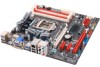
1.5 MOTHERBOARD LAYOUT USB_KBMS1 TZ77B/TZ75B/T77 CPU_FAN1 HDMI1 ATXPWR2 VGA1 DVI1 DDR3 _A1 DDR3 _A2 DDR3 _B1 DDR3 _B2 USB3_0 Socket 1155 C P U1 RJ45USB1 AUDIO1 F_AUDIO1 SYS_FAN2 CODEC PEX16_1 LAN PEX1_1 J FR ONT _U SB3_1 Intel Z77/Z75 H77 ATXPWR1 JCMOS1 BIOS JSPDIFOUT1 PEX16_2 - Biostar TZ77MXE | Setup Manual - Page 8
Remove Pin Cap before installation, and make good preservation for future use. When the CPU is removed, cover the Pin Cap on the empty socket to ensure pin legs won't be damaged. 2. The motherboard might equip with two different types of pin cap. Please refer below instruction to remove the pin cap - Biostar TZ77MXE | Setup Manual - Page 9
TZ77B/TZ75B/T77 Step 3: Hold processor with your thumb and index fingers, oriented as shown. Align the notches load plate. Pressing down on the load plate, close and engage the socket lever. Step 5: Put the CPU Fan and heatsink assembly on the CPU and buckle it on the retention frame. Connect the CPU - Biostar TZ77MXE | Setup Manual - Page 10
Motherboard Manual 2.2 FAN HEADERS These fan headers support cooling-fans built in the computer. The fan cable and connector may be different according to the fan manufacturer. Connect the fan cable to the connector while matching the black wire to pin#1. CPU_FAN1: CPU Fan Header Pin Assignment 1 - Biostar TZ77MXE | Setup Manual - Page 11
2.3 INSTALLING SYSTEM MEMORY A. Memory Modules TZ77B/TZ75B/T77 D DR3_A1 DD R3_A2 DD R3_B1 DD R3_B2 1. Unlock a DIMM slot by pressing the retaining clips outward. Align a DIMM on the slot such that - Biostar TZ77MXE | Setup Manual - Page 12
Motherboard Manual B. Memory Capacity DIMM Socket Location DDR3 Module DDR3_A1 512MB/1GB/2GB/4GB/8GB DDR3_A2 512MB/1GB/2GB/4GB/8GB DDR3_B1 512MB/1GB/2GB/4GB/8GB DDR3_B2 512MB/1GB/2GB/4GB/8GB Total Memory Size Max is 32GB. C. Dual Channel Memory Installation Please refer to the following - Biostar TZ77MXE | Setup Manual - Page 13
2.4 CONNECTORS AND SLOTS TZ77B/TZ75B/T77 SATA1/SATA2: Serial ATA3 Connectors The motherboard has a PCI to SATA Controller with 2 channels SATA interface, it satisfies the SATA 3.0 spec and with transfer rate of 6.0Gb/s. SATA1 SATA2 741 Pin Assignment 1 Ground 2 TX+ 3 TX4 Ground 5 RX6 RX+ 7 - Biostar TZ77MXE | Setup Manual - Page 14
Motherboard Manual PEX16_1: PCI-Express Gen3 x16 Slot - PCI-Express 3.0 compliant. - Maximum theoretical realized bandwidth of 16GB/s simultaneously per direction, for an aggregate of 32GB/s totally. - PCI-E 3.0 is supported by Core i7-3xxx / i5-3xxx CPU. PEX16_2: PCI-Express Gen2 x4 Slot - PCI- - Biostar TZ77MXE | Setup Manual - Page 15
TZ77B/TZ75B/T77 PCI1/PCI2: Peripheral Component Interconnect Slots This motherboard is equipped with 2 standard PCI slots. PCI stands for Peripheral Component Interconnect, and it is a bus standard for expansion cards. This PCI slot is designated - Biostar TZ77MXE | Setup Manual - Page 16
Motherboard Manual ATXPWR1: ATX Power Source Connector This connector allows user to connect 24-pin power connector on the ATX power supply. 12 24 1 13 Pin Assignment - Biostar TZ77MXE | Setup Manual - Page 17
TZ77B/TZ75B/T77 CHAPTER 3: HEADERS & JUMPERS SETUP 3.1 HOW TO SETUP Pin Assignment 1 +5V 2 N/A 3 N/A 4 Speaker 5 HDD LED (+) 6 HDD LED (-) 7 Ground 8 Reset control Function Pin 9 Speaker 10 Connector 11 12 Hard drive 13 LED 14 Reset button 15 16 Assignment N/A N/A N/A Power - Biostar TZ77MXE | Setup Manual - Page 18
Motherboard Manual F_USB1/F_USB2: Headers for USB 2.0 Ports at Front Panel These headers allow user to connect additional USB cable on the PC front panel, and also can be connected with internal USB devices, like USB card reader. Pin Assignment 1 +5V (fused) 2 +5V (fused) 3 USB- 4 USB- 5 USB+ - Biostar TZ77MXE | Setup Manual - Page 19
TZ77B/TZ75B/T77 F_AUDIO1: Front Panel Audio Header This header allows user to connect the front audio output cable with the PC front panel. This header supports 1 CIR1: Consumer IR Connector This header is for infrared remote control and communication. 26 15 Pin Assignment 1 IrDA serial input 2 - Biostar TZ77MXE | Setup Manual - Page 20
Motherboard Manual JCMOS1: Clear CMOS Header Placing the jumper on pin2-3 allows user to restore the BIOS safe setting and the CMOS data. Please carefully follow the procedures to avoid damaging the motherboard. 13 Pin 1-2 Close: Normal Operation (default). 13 13 Pin 2-3 Close: Clear CMOS data. ※ - Biostar TZ77MXE | Setup Manual - Page 21
TZ77B/TZ75B/T77 BIOS POST Code/CPU Temperature Indicator This indicator will show POST code while booting. After the booting sequence, it will show current CPU temperature through hexadecimal figure. Please refer to Chapter 6.3 for all the BIOS POST codes. On-Board Buttons There are 2 on-board - Biostar TZ77MXE | Setup Manual - Page 22
Motherboard Manual CHAPTER 4: RAID / AHCI FUNCTIONS 4.1 OPERATING SYSTEM CHIP Intel Z77/Z75/H77 SATA1/SATA2/ SATA3/SATA4/ SATA5/SATA6 Intel Z77/Z75/H77 SATA1/SATA2/ SATA3/SATA4/ SATA5/SATA6 SATA Controller Configuration AHCI Supporting OS Windows XP SP2 (32 and 64 bit) Windows Vista SP2 (32 and - Biostar TZ77MXE | Setup Manual - Page 23
SATA\7\F6flpy 64\Driver \ 2. Follow Windows 7 / Vista indication to load the driver in the installation process. 4.2 RAID ARRAYS CONNECTOR SATA1/SATA2 SATA3/SATA4/SATA5/SATA6 BY CHIP Intel Z77/Z75/H77 Intel Z77/Z75/H77 SPEED 6 Gb/s. 3 Gb/s. Support RAID 0 / 1 / 5 / 10 RAID 0 / 1 / 5 / 10 RAID - Biostar TZ77MXE | Setup Manual - Page 24
Motherboard Manual 4.3 HOW RAID WORKS RAID 0: The controller "stripes" data across multiple drives in a RAID 0 array system. It breaks up a large : Does not deliver any fault tolerance. If any drive in the array fails, all data is lost. Fault Tolerance: No. Block 1 Block 3 Block 5 Block 2 - Biostar TZ77MXE | Setup Manual - Page 25
Benefits Drives: Minimum 2, and maximum is 2. Uses: RAID 1 is ideal for small databases or any other application that requires fault tolerance and minimal capacity. Benefits: Provides 100% data redundancy. Should one drive fail, the controller switches to the other drive. Drawbacks: Requires - Biostar TZ77MXE | Setup Manual - Page 26
Motherboard Manual RAID 10: RAID 1 drives can be stripped using RAID 0 techniques. Resulting in a RAID 10 solution for improved resiliency, performance and performance, allowing for automatic redundancy. May be simultaneously used with other RAID levels in an array, and allows for spare disks. - Biostar TZ77MXE | Setup Manual - Page 27
TZ77B/TZ75B/T77 RAID 5: RAID 5 stripes both data and parity information across three or more drives itself. Features and Benefits Drives: Minimum 3. Uses: RAID 5 is recommended for transaction processing and general purpose service. Benefits: An ideal combination of good performance, good fault - Biostar TZ77MXE | Setup Manual - Page 28
Motherboard Manual 4.4 INTEL SMART RESPONSE TECHNOLOGY With Intel(R) Smart Response Technology, the performance of RAID with an Intel SSD drive can be improved better. This function is only for TZ77B and T77. Installing Smart Response Technology 1. Install RAID drives (RAID 0, 1, 5) and an Intel SSD - Biostar TZ77MXE | Setup Manual - Page 29
TZ77B/TZ75B/T77 CHAPTER 5: T-SERIES UEFI BIOS & SOFTWARE 5.1 T-SERIES UEFI BIOS T-Series UEFI BIOS Features Overclocking Navigator Engine (O.N.E.) Self Recovery System (S.R.S) Smart Fan Function BIO-Flasher: Update UEFI BIOS file from USB Flash Drive !! WARNING !! For better system performance, the - Biostar TZ77MXE | Setup Manual - Page 30
in the default UEFI BIOS setting, and all overclock settings will be re-configured. C. Smart Fan Function Smart Fan Function is under "Smart Fan Control" in "Advanced Menu". This is a brilliant feature to control CPU/System Temperature vs. Fan speed. When enabling Smart Fan function, Fan speed is - Biostar TZ77MXE | Setup Manual - Page 31
TZ77B/TZ75B/T77 CPU Smart FAN This item allows you to control the CPU Smart Fan function. CPU FAN Calibrate Press [ENTER] to calibrate CPU FAN. Control Mode This item provides several operation modes of the fan. Fan Ctrl OFF(℃) When CPU temperature is lower than this value, the CPU fan will keep - Biostar TZ77MXE | Setup Manual - Page 32
Motherboard Manual 5.2 T-SERIES SOFTWARE Installing T-Series Software 1. Insert the Setup DVD to the optical drive. The driver installation program would appear if the Auto-run function has been enabled. 2. Select Software Installation, and then click on the respective software title. 3. Follow the - Biostar TZ77MXE | Setup Manual - Page 33
TZ77B/TZ75B/T77 The CPU tab provides information on the CPU and motherboard. The Memory tab provides information on the memory module(s). You can select memory module on a specific slot to see its information. The OC Tweaker tab allows you to change system clock settings and voltages settings. It - Biostar TZ77MXE | Setup Manual - Page 34
Motherboard Manual 3 Pre-set Modes: V6, V12, AUTO for different overclocking experience. The HW Monitor tab allows you to monitor hardware voltage, fan speed, and temperature. Besides, you also can set related values for CPU Smart Fan. 32 - Biostar TZ77MXE | Setup Manual - Page 35
TZ77B/TZ75B/T77 Pressing TOVERCLOCKER logo displays information about manufacturer and software version. You can update current version by clicking the button "Live Update." Green Power II Utility BIOSTAR G.P.U II (Green Power Utility) is a new function. The utility enhances energy efficiency by - Biostar TZ77MXE | Setup Manual - Page 36
Motherboard Manual G.P.U Mode Setting This utility provides five modes, upon your requirements, to improve system performance or to save power consumption. Note: Even if the modes saving - Biostar TZ77MXE | Setup Manual - Page 37
TZ77B/TZ75B/T77 eHot-Line (Optional) eHot-Line is a convenient utility that helps you to contact with our Tech-Support system. This utility will collect the system information which is useful for analyzing the problem you may have encountered, and then send these information to our tech-support - Biostar TZ77MXE | Setup Manual - Page 38
your system information including motherboard/BIOS/CPU/video/ device/OS information. This information is also concluded in the sent mail. We will not share customer's data with any other third parties, so please feel free to provide your system information while using eHot-Line service. If you are - Biostar TZ77MXE | Setup Manual - Page 39
BIOS Update TZ77B/TZ75B/T77 BIOS Update is a convenient utility which allows you to update your motherboard BIOS under Windows system. AWARD BIOS Show current BIOS information AMI BIOS Clear CMOS function (Only for AWARD BIOS) Save current BIOS to a .bin file Update BIOS with - Biostar TZ77MXE | Setup Manual - Page 40
Motherboard Manual Before doing this, please download the proper BIOS file from the website. For AWARD BIOS, update BIOS procedure should be run with Clear CMOS function, so please check on Clear CMOS first. Then click Update BIOS button, a dialog will show for asking you backup - Biostar TZ77MXE | Setup Manual - Page 41
BMP as your boot logo so as to customize your computer. Please follow the following instructions to update boo logo: 1. Load Image:Choose the picture as the boot logo. 2. Transform:Transform the picture for BIOS and preview the result. 3. Update Bios:Write the picture to BIOS Memory to complete the - Biostar TZ77MXE | Setup Manual - Page 42
optical drive. A. Driver Installation To install the driver, please click on the Driver icon. The setup guide will list the compatible driver for your motherboard and operating system. Click on each device driver to launch the installation program. B. Software Installation To install the software - Biostar TZ77MXE | Setup Manual - Page 43
3. CPU fan speed is fulfilling with the CPU speed. After confirmed, please follow steps below to relief the CPU protection function. 1. Remove the power cord from power supply for seconds. 2. Wait for seconds. 3. Plug in the power cord and boot up the system. Or you can: 1. Clear the CMOS data. (See - Biostar TZ77MXE | Setup Manual - Page 44
Motherboard Manual 6.3 AMI BIOS POST CODE Checkpoint 03 04 05 06 07 08 C0 C1 C2 C5 C6 C7 0A 0B 0C 0E 13 20 24 2A 2C 2E 31 33 Description Disable NMI, Parity, video for EGA, and DMA controllers. Initialize BIOS, POST, Runtime data area. Also initialize BIOS modules on POST entry and GPNV area. - Biostar TZ77MXE | Setup Manual - Page 45
Mid POST initialization of chipset registers. Detect different devices (Parallel ports, serial ports, and coprocessor in CPU, etc.) successfully installed in the system and update the BDA, EBDA...etc. Updates CMOS memory size from memory found in memory test. Allocates memory for Extended BIOS Data - Biostar TZ77MXE | Setup Manual - Page 46
Motherboard Manual 6.4 TROUBLESHOOTING Probable Solution 1. There is no power in the system. 1. Make sure power cable is Power LED does not shine; the securely plugged in. fan of the power supply does not 2. Replace cable. work 3. Contact technical support. 2. Indicator light on keyboard - Biostar TZ77MXE | Setup Manual - Page 47
TZ77B/TZ75B/T77 This page is intentionally left blank. 45 - Biostar TZ77MXE | Setup Manual - Page 48
Motherboard Manual APPENDIX: SPEC IN OTHER LANGUAGES GERMAN Spezifikationen Unterstützt Execute Disable Bit / Enhanced Intel Socket 1155 SpeedStep® / Intel Architecture-64 / Extended CPU Intel Core i7 / i5 / i3 / Pentium / Celeron Memory 64 Technology / Virtualization Technology / - Biostar TZ77MXE | Setup Manual - Page 49
-Lüfter-Sockel "CMOS löschen"-Sockel USB2.0-Anschluss USB3.0-Anschluss Verbraucher-IR Anschluss Serieller Anschluss S/PDIF Ausgangsanschluss Stromanschluss (24-polig) Stromanschluss (8-polig) PS/2-Tastatur HDMI-Anschluss VGA-Anschluss Rückseiten-E DVI-Anschluss /A LAN-Anschluss USB2 - Biostar TZ77MXE | Setup Manual - Page 50
SPEC Prend en charge les technologies d'exécution de bit Socket 1155 de désactivation / Intel SpeedStep® optimisée/ UC Processeurs Intel Core i7 / i5 / i3 / Pentium / d'architecture Intel 64 / de mémoire étendue 64 / de Celeron virtualisation / Hyper Threading Chipset Intel Z77 (TZ77B - Biostar TZ77MXE | Setup Manual - Page 51
TZ77B/TZ75B/T77 SPEC me Embase d'effacement CMOS x1 Connecteur USB2.0 HDMI x1 Port VGA x1 E/S du Port DVI x1 panneau Port LAN x1 arrière Port USB2.0 x4 Port USB3.0 x2 Fiche audio x6 Dimensions 220 mm (l) X 295 mm (H) ATX de la carte Support SE Windows XP / Vista / 7 Biostar - Biostar TZ77MXE | Setup Manual - Page 52
Motherboard Manual ITALIAN SPECIFICA CPU Socket 1155 Processore Intel Core i7 / i5 / i3 / Pentium / Celeron Supporto di Execute Disable Bit / Enhanced Intel SpeedStep® / Architettura Intel 64 / Tecnologia Extended Memory 64 / Tecnologia Virtualization / Hyper Threading Chipset Intel Z77 ( - Biostar TZ77MXE | Setup Manual - Page 53
TZ77B/TZ75B/T77 SPECIFICA Collettore ventolina CPU Alimentazione ventolina CPU (con funzione x1 Smart Fan) Collettore ventolina sistema x2 Alimentazione ventolina di sistema Collettore cancellaz ione CMOS x1 Connettore USB2.0 Ciascun connettore supporta 2 porte USB2.0 x2 pannello frontale - Biostar TZ77MXE | Setup Manual - Page 54
1155 SpeedStep® Mejorado / Intel Architecture-64 / CPU Procesador Intel Core i7 / i5 / i3 / Pentium / Tecnología Extended Memory 64 / Tecnología de Celeron virtualización / Hyper Threading Conjunto de Intel Z77 (TZ77B), Intel Z75 (TZ75B) chips Intel H77 (T77) IT8728 Iniciativas de control - Biostar TZ77MXE | Setup Manual - Page 55
de ventilador de sistema Cabecera de borrado de CMOS X1 Conector USB2.0 X2 Cada conector soporta 2 puertos USB2.0 frontales Conector USB3.0 X1 Cada conector soporta 2 puertos USB3.0 frontales Conector de IR del consumidor X1 Puerto serie X1 Conector de salida S/PDIF X1 Soporta funci - Biostar TZ77MXE | Setup Manual - Page 56
Motherboard Manual PORTUGUESE ESPECIFICAÇÕES Suporta as tecnologias Execute Disable Bit / Socket 1155 Enhanced IntelSpeedStep® / Intel Arquitecture -64 CPU Processador Intel Core i7 / i5 / i3 / Pentium / / Extended Memory 64 / Virtualization / Hyper Celeron Threading Chipset Intel Z77 ( - Biostar TZ77MXE | Setup Manual - Page 57
CPU x1 Smart Fan) Conector da ventoinha do sistema x2 Alimentação da ventoinha do sistema Conector para limpeza do CMOS x1 Conectores (8 pinos) Teclado PS/2 x1 Porta HDMI x1 Entradas/S Porta VGA x1 aídas no Porta DVI x1 painel Porta LAN x1 traseiro Porta USB2.0 x4 Porta USB3 - Biostar TZ77MXE | Setup Manual - Page 58
Motherboard Manual POLISH SPEC Procesor Socket 1155 Procesor Intel Core i7 / i5 / i3 / Pentium / Celeron Obsługa Execute Disable Bit / Enhanced Intel SpeedStep® / Intel Architecture-64 / Extended Memory 64 Technology / Virtualization Technology / Hyper Threading Chipset Intel Z77 (TZ77B), - Biostar TZ77MXE | Setup Manual - Page 59
TZ77B/TZ75B/T77 SPEC Złącze główkowe wentylatora systemowego Zasilanie wentylatora systemowego x2 Złącze główkowe kasowania CMOS x1 Złącze USB2.0 Każde złącze obsługuje 2 porty USB2.0 na panelu x2 przednim Złącze USB3.0 Każde złącze obsługuje 2 porty USB3.0 na panelu - Biostar TZ77MXE | Setup Manual - Page 60
Motherboard Manual RUSSIAN СПЕЦ CPU Execute Disable Bit / Socket 1155 Enhanced Intel SpeedStep® / Intel Architecture-64 Intel Core i7 / i5 / i3 / Pentium / ый Celeron / Extended Memory 64 Technology Hyper Threading Набор Intel Z77 (TZ77B), Intel Z75 (TZ75B) Intel H77 - Biostar TZ77MXE | Setup Manual - Page 61
.0 2 USB3.0 x1 x1 S/PDIF 24 вывод) x1 x1 x1 8 вывод) x1 PS/2 x1 Порт HDMI x1 Задняя Порт VGA x1 панель Порт DVI x1 LAN x1 USB2.0-порт x4 USB3.0-порт x2 ода x6 220 мм (Ш) X 295 мм (В) Windows XP / Vista / 7 OS ATX Biostar OS 59 - Biostar TZ77MXE | Setup Manual - Page 62
Motherboard Manual ARABIC Execute Disable Bit / Enhanced Intel SpeedStep® / Intel Architecture-64 / Extended Memory 64 Technology / Virtualization Technology / Hyper Threading Socket 1155 Intel Core i7 / i5 / i3 / Pentium Celeron )Intel Z77 (TZ77B), Intel Z75 - Biostar TZ77MXE | Setup Manual - Page 63
1 CMOS 2 USB2.0 USB2.0 1 USB3.0 USB3.0 1 1 1 S/PDIF 1 24 1 8 1 PS/2 1 HDMI 1 VGA 1 DVI 1 4 USB2.0 2 USB3.0 6 ATX 295 220 X Biostar - Biostar TZ77MXE | Setup Manual - Page 64
Motherboard Manual JAPANESE 仕様 Execute Disable Bit / Enhanced Intel SpeedStep® / Socket 1155 Intel Architecture-64 / Extended Memory 64 CPU Intel Core i7 / i5 / i3 / Pentium / Celeron プロ Technology / Virtualization Technology / Hyper セッサ Threading Intel Z77 (TZ77B), Intel Z75 (TZ75B - Biostar TZ77MXE | Setup Manual - Page 65
PS/2 HDMIポート VGAポート DVI-Dポート I/O LANポート USB2.0ポート USB3.0ポート 220 mm (幅) X 295 mm (高さ) OS Windows XP / Vista / 7 TZ77B/TZ75B/T77 仕様 x1 CPU x2 x1 2 USB2.0 x2 2 USB3.0 x1 x1 x1 x1 x1 x1 x1 x1 x1 x1 x1 x4 x2 x6 ATX Biostar OS 2012
-
 1
1 -
 2
2 -
 3
3 -
 4
4 -
 5
5 -
 6
6 -
 7
7 -
8
-
9
-
10
-
11
-
12
-
13
-
14
-
15
-
16
-
17
-
18
-
19
-
20
-
21
-
22
-
23
-
24
-
25
-
26
-
27
-
28
-
29
-
30
-
31
-
32
-
33
-
34
-
35
-
36
-
37
-
38
-
39
-
40
-
41
-
42
-
43
-
44
-
45
-
46
-
47
-
48
-
49
-
50
-
51
-
52
-
53
-
54
-
55
-
56
-
57
-
58
-
59
-
60
-
61
-
62
-
63
-
64
-
65
 |
 |

TZ77B/TZ75B/T77 Setup Manual
FCC Information and Copyright
This equipment has been tested and found to comply with the limits of a Class
B digital device, pursuant to Part 15 of the FCC Rules. These limits are designed
to provide reasonable protection against harmful interference in a residential
installation. This equipment generates, uses, and can radiate radio frequency
energy and, if not installed and used in accordance with the instructions, may
cause harmful interference to radio communications. There is no guarantee
that interference will not occur in a particular installation.
The vendor makes no representations or warranties with respect to the
contents here and specially disclaims any implied warranties of merchantability
or fitness for any purpose. Further the vendor reserves the right to revise this
publication and to make changes to the contents here without obligation to
notify any party beforehand.
Duplication of this publication, in part or in whole, is not allowed without first
obtaining the vendor’s approval in writing.
The content of this user’s manual is subject to be changed without notice and
we will not be responsible for any mistakes found in this user’s manual. All the
brand and product names are trademarks of their respective companies.
Dichiarazione di conformità
sintetica
Ai sensi dell’art. 2 comma 3 del D.M.
275 del 30/10/2002
Si dichiara che questo prodotto è
conforme alle normative vigenti e
soddisfa i requisiti essenziali richiesti
dalle direttive
2004/108/CE, 2006/95/CE e
1999/05/CE
quando ad esso applicabili
Short Declaration of conformity
We declare this product is complying
with the laws in force and
meeting all
the essential requirements as specified
by the directives
2004/108/CE, 2006/95/CE and
1999/05/CE
whenever these laws may be applied