Biostar TZ77XE4 Setup Manual
Biostar TZ77XE4 Manual
 |
View all Biostar TZ77XE4 manuals
Add to My Manuals
Save this manual to your list of manuals |
Biostar TZ77XE4 manual content summary:
- Biostar TZ77XE4 | Setup Manual - Page 1
TZ77XE4 Setup Manual FCC Information and Copyright This equipment has been tested and found to comply with the limits of a radio frequency energy and, if not installed and used in accordance with the instructions, may cause harmful interference to radio communications. There is no guarantee that - Biostar TZ77XE4 | Setup Manual - Page 2
Settings 15 Chapter 4: RAID / AHCI Functions 20 4.1 Operating System 20 4.2 Raid Arrays 21 4.3 How RAID Works 22 4.4 Smart Response Technology 26 Chapter 5: T-Series UEFI BIOS & Software........... 27 5.1 T-Series UEFI BIOS 27 5.2 T-Series Software 30 Chapter 6: Useful Help 42 6.1 Driver - Biostar TZ77XE4 | Setup Manual - Page 3
TZ77XE4 1.1 BEFORE YOU START Thank you for choosing our product. Before you start installing the motherboard, please make sure you follow the instructions below: „ Prepare a dry and stable working environment with sufficient lighting Panel for ATX Case X 1 User's Manual X 1 Fully Setup Driver DVD X - Biostar TZ77XE4 | Setup Manual - Page 4
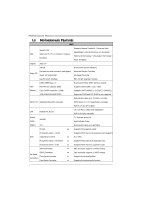
Manual 1.3 MOTHERBOARD FEATURES SPEC Supports Execute Disable Bit / Enhanced Intel Socket 1155 SpeedStep® / Intel Architecture-64 / Extended CPU Intel Core i7 / i5 / i3 / Pentium / Celeron Memory 64 Technology / Virtualization Technology / processor Hyper Threading Chipset Intel Z77 - Biostar TZ77XE4 | Setup Manual - Page 5
Port USB3.0 Port Audio Jack Board Size 244 (W) x 305 (L) mm OS Support Windows XP / Vista / 7 TZ77XE4 SPEC x1 CPU Fan power supply (with Smart Fan function) x2 System Fan In/Out and Mic. connection ATX Biostar reserves the right to add or remove support for any OS with or without notice 3 - Biostar TZ77XE4 | Setup Manual - Page 6
Motherboard Manual 1.4 REAR PANEL CONNECTORS PS /2 Ke yb oard Display Port VGA eS ATA LA N USB2.0X2 HDMI DV I- D USB3.0X2 USB2.0X2 Cen ter Rear Side Line In Line Ou t Mic In NOTE: USB3.0 (only supported X z A = Single Pipe Single Display, Intel® Dual Display Clone (Only 24-bpp), or - Biostar TZ77XE4 | Setup Manual - Page 7
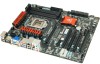
1.5 MOTHERBOARD LAYOUT USB_KBMS1 HDMI_DP1 ATXPW R1 TZ77XE4 CPU_FAN1 DDR3_A1 DDR3_A2 DDR3_B1 DDR3_B2 VGA1 DVI1 DUALUSB _ESATA1 RJ45USB1 Socket 1155 CP U 1 AUDIO1 PEX16_1 ATXPWR2 CO DEC_LE D_D2 CODE C_LE D_D1 LAN PEX1_1 F_AUDIO1 CODEC PEX16_2 PCI1 BIOS Intel Z77 BAT1 SATA2 SATA1 - Biostar TZ77XE4 | Setup Manual - Page 8
CPU is removed, cover the Pin Cap on the empty socket to ensure pin legs won't be damaged. 2. The motherboard might equip with two different types of pin cap. Please refer below instruction to remove the pin cap. Step 1: Pull the socket locking lever out from the socket and then raise the - Biostar TZ77XE4 | Setup Manual - Page 9
TZ77XE4 Step 3: Hold processor with your thumb and index fingers, oriented as shown. Align the notches with the socket. Lower the processor straight down without tilting - Biostar TZ77XE4 | Setup Manual - Page 10
Motherboard Manual 2.2 FAN HEADERS These fan headers support cooling-fans built in the computer. The 13 Note: The SYS_FAN1/SYS_FAN2 support 3-pin head connectors; the CPU_FAN1 supports 4-pin head connector. When connecting with wires onto connectors, please note that the red wire is the positive and - Biostar TZ77XE4 | Setup Manual - Page 11
A. Memory Modules TZ77XE4 D DR3_A1 DD R3_A2 DD R3_B1 DD R3_B2 1. Unlock a DIMM slot by pressing the retaining clips outward. Align a DIMM on the slot such that the notch on the DIMM matches the break on the Slot. 2. Insert the DIMM vertically and firmly into the slot until the retaining chip snap - Biostar TZ77XE4 | Setup Manual - Page 12
Motherboard Manual B. Memory Capacity DIMM Socket Location DDR3 Module DDR3_A1 512MB/1GB/2GB/4GB/8GB DDR3_A2 512MB/1GB/2GB/4GB/8GB DDR3_B1 512MB/1GB/2GB/4GB/8GB DDR3_B2 512MB/1GB/2GB/4GB/8GB Total Memory Size Max is 32GB. C. Dual Channel Memory Installation Please refer to the following - Biostar TZ77XE4 | Setup Manual - Page 13
AND SLOTS TZ77XE4 SATA1~SATA4: Serial ATA Connectors This motherboard provides several SATA controllers for connecting to SATA devices with respective spec and transfer rates as bellows: CONNECTOR SATA1-U/L SATA2-U/L ; SATA3-U/L SATA4 PM1-U/PM0-L BY CHIP SPEED Support Intel Z77 6 Gb/s. RAID - Biostar TZ77XE4 | Setup Manual - Page 14
Motherboard Manual PEX16_1/ PEX16_2: PCI-Express Gen3 x16 (x16 / x8) (Nvidia SLI and AMD CrossFireX) is x16, or x8 when SLI / CFX is enabled; the speed of PEX16_2 is x8. - PCI-E 3.0 is supported by Core i7-3xxx / i5-3xxx CPU. Note: For more details about Nvidia SLI and AMD CrossFireX, please access - Biostar TZ77XE4 | Setup Manual - Page 15
TZ77XE4 PCI1/PCI2: Peripheral Component Interconnect Slots This motherboard is equipped with 2 standard PCI slots. PCI stands for Peripheral Component Interconnect, and it is a bus standard for expansion cards. This PCI slot is designated as 32 bits. PCI 1 PCI2 ATXPWR1: ATX Power Source Connectors - Biostar TZ77XE4 | Setup Manual - Page 16
Motherboard Manual ATXPWR2: ATX Power Source Connector This connector allows user to connect 24-pin power connector on the ATX power supply. 12 24 1 13 Pin Assignment Pin Assignment 13 +3.3V 14 -12V 15 Ground 16 PS_ON 17 Ground 18 Ground 19 Ground 20 NC - Biostar TZ77XE4 | Setup Manual - Page 17
TZ77XE4 CHAPTER 3: HEADERS & JUMPERS SETUP 3.1 HOW TO SETUP JUMPERS The illustration shows how to set up jumpers. When the jumper cap is placed on pins, the jumper is "close", if not, that means the jumper is "open". Pin opened Pin closed Pin1-2 closed 3.2 DETAIL SETTINGS PANEL1: Front Panel - Biostar TZ77XE4 | Setup Manual - Page 18
Motherboard Manual F_USB1/F_USB2: Headers for USB 2.0 Ports at Front Panel These headers allow user to connect additional USB cable on the PC front panel, and also can be connected with internal USB devices, like USB card reader. F_ USB 20 Key NOTE: USB3.0 is only supported by Windows 7. 16 - Biostar TZ77XE4 | Setup Manual - Page 19
TZ77XE4 F_AUDIO1: Front Panel Audio Header This header allows user to connect the front audio output cable with the PC front panel. This header supports HD and AC'97 audio front panel connector. Pin Assignment 1 Mic Left in 2 Ground 3 Mic Right in 4 GPIO 5 Right line in 2 10 6 7 Jack - Biostar TZ77XE4 | Setup Manual - Page 20
Motherboard Manual J_COM1: Serial Port Connector The motherboard has a Serial Port Connector for connecting RS-232 Port. 2 10 1 9 Pin Assignment 1 Carrier detect 2 Received data 3 Transmitted data 4 Data terminal ready 5 Signal ground 6 Data set ready 7 Request to send 8 Clear - Biostar TZ77XE4 | Setup Manual - Page 21
On-Board Buttons There are 3 on-board buttons. TZ77XE4 CL_CMOS_BTN RST_BTN PWR_BTN PWR_BTN: This is an on-board Power Switch button. RST_BTN: This is an on-board Reset button. CL_CMOS_BTN: Clear CMOS Button You can use this button to reset the BIOS to default. 19 - Biostar TZ77XE4 | Setup Manual - Page 22
Motherboard Manual CHAPTER 4: RAID / AHCI FUNCTIONS 4.1 OPERATING SYSTEM CHIP Intel Z77 SATA1-U/SATA1-L/ SATA2-U/SATA2-L/ SATA3-U/SATA3-L/ eSATA Intel Z77 SATA1-U/SATA1-L/ SATA2-U/SATA2-L/ SATA3-U/SATA3-L/ eSATA ASM1061 SATA4 PM1-U/ SATA4 PM0-L SATA Controller Configuration AHCI OS Windows XP SP2 - Biostar TZ77XE4 | Setup Manual - Page 23
7 / Vista indication to load the driver in the installation process. 4.2 RAID ARRAYS CONNECTOR BY CHIP SPEED Support SATA2-U/SATA2-L/SATA3-U/ Intel Z77 SATA3-L/eSATA 3 Gb/s. RAID 0 / 1 / 5 / 10 SATA1-U/SATA1-L Intel Z77 6 Gb/s. RAID 0 / 1 / 5 / 10 RAID supports the following types of RAID - Biostar TZ77XE4 | Setup Manual - Page 24
Motherboard Manual 4.3 HOW RAID WORKS RAID 0: The controller "stripes" data across multiple drives in a size of each block is determined by the stripe size parameter, which you set during the creation of the RAID set based on the system environment. This technique reduces overall disk access time and - Biostar TZ77XE4 | Setup Manual - Page 25
TZ77XE4 RAID 1: Every read and write is actually carried out in parallel across 2 can be applied for high-availability solutions, or as a form of automatic backup that eliminates tedious manual backups to more expensive and less reliable media. Features and Benefits Drives: Minimum 2, and maximum - Biostar TZ77XE4 | Setup Manual - Page 26
Motherboard Manual RAID 10: RAID 1 drives can be stripped using RAID 0 techniques. Resulting in a RAID 10 solution for improved resiliency, performance and rebuild performance. Features and Benefits - Biostar TZ77XE4 | Setup Manual - Page 27
TZ77XE4 RAID 5: RAID 5 stripes both data and parity information across three or more Drives: Minimum 3. Uses: RAID 5 is recommended for transaction processing and general purpose service. Benefits: An ideal combination of good performance, good fault tolerance, and high capacity and storage - Biostar TZ77XE4 | Setup Manual - Page 28
SSD. 2. Activate RAID mode from BIOS, and install operating system. 3. Insert the Setup DVD to the optical drive, and Install all drivers (including Intel(R) Smart Response Technology Driver). After all processes finish, reboot the system. 4. Intel(R) SRT service icon will show in notification area - Biostar TZ77XE4 | Setup Manual - Page 29
BIOS Manual in the Setup DVD. A. Overclocking Navigator Engine (O.N.E.) O.N.E provides 4 systems allowing users to customize personal overclock settings: Manual CPU System, Manual Memory System, Manual PWM System, and Manual Voltage System. Notice: Not all types of Intel CPU perform above overclock - Biostar TZ77XE4 | Setup Manual - Page 30
the system starts up. However, it can prevent system hang-up due to inappropriate overclock actions. When the system hangs up, S.R.S. will automatically log in the default UEFI BIOS setting, and all overclock settings will be re-configured. C. Smart Fan Function Smart Fan Function is under "Smart - Biostar TZ77XE4 | Setup Manual - Page 31
TZ77XE4 CPU Smart FAN This item allows you to control the CPU Smart Fan function. fan controller will turn on. The range is from 0~127, with an interval of 1. Fan Ctrl Start Value This item sets CPU FAN Start Speed Value. The range is from 0~127, with an interval of 1. Fan Ctrl Sensitive The bigger - Biostar TZ77XE4 | Setup Manual - Page 32
Motherboard Manual 5.2 T-SERIES SOFTWARE Installing T-Series Software 6. Insert the Setup DVD to the optical drive. The driver Memory. Smart-Fan management and PC health are for monitoring system status. This utility also allows you to make overclocking profiles saving unlimitedly, and pre-set - Biostar TZ77XE4 | Setup Manual - Page 33
TZ77XE4 The CPU tab provides information on the CPU and motherboard. The Memory tab provides information on the memory module(s). You can select memory module on a specific slot to see its information. The OC Tweaker tab allows you to change system clock settings and voltages settings. It also - Biostar TZ77XE4 | Setup Manual - Page 34
Motherboard Manual 3 Pre-set Modes: V6, V12, AUTO for different overclocking experience. The HW Monitor tab allows you to monitor hardware voltage, fan speed, and temperature. Besides, you also can set related values for CPU Smart Fan. 32 - Biostar TZ77XE4 | Setup Manual - Page 35
and software version. You can update current version by clicking the button "Live Update." Green Power II Utility BIOSTAR G.P.U II (Green Power Utility) is a new function. The utility enhances energy efficiency by disabling extra phases while CPU is on light loading; it features 4+1 power phases - Biostar TZ77XE4 | Setup Manual - Page 36
Motherboard Manual G.P.U Mode Setting This utility provides five modes, upon your requirements, to improve system performance or to save power consumption. Note: Even if the modes saving more power - Biostar TZ77XE4 | Setup Manual - Page 37
: Any chipset with integrated graphics output „Discrete GPU: Any Nvidia/AMD GPU with DX9/DX10/DX11 support „Memory Size: 2GB „Operating System: Windows 7 32-bit and 64-bit „Hard Disk Space: 20MB BIOS Setting Please try to set Onboard VGA (IGD) as first display if you want to use the i-mode. i-Mode - Biostar TZ77XE4 | Setup Manual - Page 38
Motherboard Manual Software Installation 1. Install VGA Driver and VIRTU MVP Software. 2. If for some reason auto-activation process fails, or the internet is not available for 30 days, user will have to manually activate Virtu Universal MVP by pressing "Activate" button through the Internet. 3. - Biostar TZ77XE4 | Setup Manual - Page 39
information to our tech-support department to help you fix the problem. Before you use this utility,please set Outlook Express as address that you would like to send t he copy to. *Provid e the name of the memory module ma nufa ct u rer. Provid e the name of the power supply manufacturer and the - Biostar TZ77XE4 | Setup Manual - Page 40
your system information including motherboard/BIOS/CPU/video/ device/OS information. This information is also concluded in the sent mail. We will not share customer's data with any other third parties, so please feel free to provide your system information while using eHot-Line service. If you are - Biostar TZ77XE4 | Setup Manual - Page 41
BIOS Update TZ77XE4 BIOS Update is a convenient utility which allows you to update your motherboard BIOS under Windows system. AWARD BIOS Show current BIOS information AMI BIOS Clear CMOS function (Only for AWARD BIOS) Save current BIOS to a .bin file Update BIOS with a BIOS - Biostar TZ77XE4 | Setup Manual - Page 42
Motherboard Manual Before doing this, please download the proper BIOS file from the website. For AWARD BIOS, update BIOS procedure should be run with Clear CMOS function, so please check on Clear CMOS first. Then click Update BIOS button, a dialog will show for asking you backup - Biostar TZ77XE4 | Setup Manual - Page 43
BMP as your boot logo so as to customize your computer. Please follow the following instructions to update boo logo: 1. Load Image:Choose the picture as the boot logo. 2. Transform:Transform the picture for BIOS and preview the result. 3. Update Bios:Write the picture to BIOS Memory to complete the - Biostar TZ77XE4 | Setup Manual - Page 44
Motherboard Manual CHAPTER 6: USEFUL HELP 6.1 DRIVER INSTALLATION NOTE After you installed your operating system, please insert the Fully Setup Driver DVD into your optical drive and install the driver for better system performance. You will see the following window after you insert the DVD The - Biostar TZ77XE4 | Setup Manual - Page 45
TZ77XE4 6.2 EXTRA INFORMATION CPU Overheated If the system shutdown automatically after power on system for seconds, that means the CPU protection function has been activated. When the CPU is over heated, the motherboard seconds. 3. Plug in the power cord and boot up the system. Or you can: 1. Clear - Biostar TZ77XE4 | Setup Manual - Page 46
set up application processors. Re-enable cache for boot strap processor. Early CPU Init Exit. Initializes the 8042 compatible Key Board Controller. Detects the presence of PS/2 mouse. Detects the presence of Keyboard in KBC port. Testing and initialization of different Input Devices. Also, update - Biostar TZ77XE4 | Setup Manual - Page 47
the BDA, EBDA...etc. Updates CMOS memory size from memory found in memory test. Allocates memory for Extended BIOS Data Area from base memory. Programming the memory hole or any kind of implementation that needs an adjustment in system RAM size if needed. Initializes NUM-LOCK status and programs - Biostar TZ77XE4 | Setup Manual - Page 48
Motherboard Manual 6.4 TROUBLESHOOTING Probable Solution 1. There is no power in the system. 1. Make sure power cable is Power LED does not shine; the securely plugged in. fan of the power supply does not 2. Replace cable. work 3. Contact technical support. 2. Indicator light on keyboard - Biostar TZ77XE4 | Setup Manual - Page 49
TZ77XE4 This page is intentionally left blank. 47 - Biostar TZ77XE4 | Setup Manual - Page 50
Motherboard Manual APPENDIX: SPEC IN OTHER LANGUAGES GERMAN Spezifikationen Unterstützt Execute Disable Bit / Enhanced Intel Socket 1155 SpeedStep® / Intel Architecture-64 / Extended CPU Intel Core i7 / i5 / i3 / Pentium / Celeron Memory ALC898 tützung USB3.0 Z77 PCI-Steckplatz x2 PCI - Biostar TZ77XE4 | Setup Manual - Page 51
mm (L) OS-Unterstüt Windows XP / Vista / 7 zung TZ77XE4 Spezifikationen CPU-Lüfterstromversorgungsanschluss (mit Smart x1 Fan-Funktion) x2 System-Lüfter x1 x1 x1 x1 x1 x1 x1 x1 x1 x4 x2 x6 ATX Biostar behält sich das Recht vor, ohne Ankündigung die Unterstützung für ein Betriebssystem hinzuzufügen - Biostar TZ77XE4 | Setup Manual - Page 52
Motherboard Manual FRENCH SPEC Prend en charge les technologies d'exécution de bit Socket 1155 de désactivation / Intel SpeedStep® optimisée/ UC Processeurs Intel Core i7 / i5 / i3 / Pentium / d'architecture Intel en charge ALC898 audio HD USB3.0 Z77 Fentes Fente PCI x2 Fente PCI - Biostar TZ77XE4 | Setup Manual - Page 53
TZ77XE4 SPEC Embase de ventilateur UC Alimentation électrique du ventilateur UC ( USB3.0 x2 Fiche audio x6 Dimensions 244 mm (l) X 305 mm (H) ATX de la carte Support SE Windows XP / Vista / 7 Biostar se réserve le droit d'ajouter ou de supprimer le support de SE avec ou sans préavis 51 - Biostar TZ77XE4 | Setup Manual - Page 54
Motherboard Manual ITALIAN SPECIFICA CPU Socket 1155 Processore Intel Core i7 / i5 / i3 / Pentium / Celeron Chipset Intel Z77 Supporto di Execute Disable Bit / Enhanced Intel SpeedStep® / Architettura Intel 64 / Tecnologia Extended Memory audio HD USB3.0 Z77 Supporto audio High-Definition - Biostar TZ77XE4 | Setup Manual - Page 55
TZ77XE4 SPECIFICA Collettore ventolina sistema x2 Alimentazione ventolina di sistema Collettore audio x6 Dimension 244 mm (larghezza) x 305 mm ATX i scheda (altezza) Sistemi operativi Windows XP / Vista / 7 supportati Biostar si riserva il diritto di aggiungere o rimuovere il supporto - Biostar TZ77XE4 | Setup Manual - Page 56
deshabilitación de ejecución / Intel Socket 1155 SpeedStep® Mejorado / Intel Architecture-64 / CPU Procesador Intel Core i7 / i5 / i3 / Pentium / Tecnología Extended Memory 64 / Tecnología de Celeron virtualización / Hyper Threading Conjunto de Intel Z77 chips IT8728 Iniciativas de control - Biostar TZ77XE4 | Setup Manual - Page 57
TZ77XE4 Especificación Cabecera de borrado de CMOS X1 Conector USB2.0 X2 Cada Puerto de red local X1 Puerto USB2.0 X4 Puerto USB3.0 X2 Conector de sonido X6 Tamaño de 244 mm. (A) X 305 Mm. (H) ATX la placa Soporte de sistema Windows XP / Vista / 7 operativo Biostar se reserva - Biostar TZ77XE4 | Setup Manual - Page 58
Motherboard Manual PORTUGUESE ESPECIFICAÇÕES Suporta as tecnologias Execute Disable Bit / Socket 1155 Enhanced IntelSpeedStep® / Intel Arquitecture -64 CPU Processador Intel Core i7 / i5 / i3 / Pentium / / Extended Memory 64 / Virtualization / Hyper Celeron Threading Chipset Intel Z77 - Biostar TZ77XE4 | Setup Manual - Page 59
TZ77XE4 ESPECIFICAÇÕES Alimentação da ventoinha da CPU (com a função x2 Tomada de áudio x6 Tamanho 244 mm (L) X 305 mm (A) ATX da placa Sistemas operativos Windows XP / Vista / 7 suportados A Biostar reserva-se o direito de adicionar ou remover suporte para qualquer sistema operativo - Biostar TZ77XE4 | Setup Manual - Page 60
Motherboard Manual POLISH SPEC Procesor Socket 1155 Procesor Intel Core i7 / i5 / i3 / Pentium / Celeron Obsługa Execute Disable Bit / Enhanced Intel SpeedStep® / Intel Architecture-64 / Extended Memory 64 Technology / Virtualization Technology / Hyper Threading Chipset Intel Z77 Pamięć głó - Biostar TZ77XE4 | Setup Manual - Page 61
TZ77XE4 SPEC Złącze główkowe kasowania CMOS x1 Złącze USB2.0 Każde złącze obsł x2 Gniazdo audio x6 Wymiary 244 mm (S) X 305 mm (W) ATX płyty Obsluga systemu Windows XP / Vista / 7 operacyjne go Biostar zastrzega sobie prawo dodawania lub odwoływania obsługi dowolnego systemu operacyjnego - Biostar TZ77XE4 | Setup Manual - Page 62
Motherboard Manual RUSSIAN СПЕЦ CPU Execute Disable Bit / Socket 1155 Enhanced Intel SpeedStep® / Intel Architecture-64 Intel Core i7 / i5 / i3 / Pentium / ый Celeron / Extended Memory 64 Technology Hyper Threading Набор Intel Z77 Слоты DDR3 DIMM x 4 32 DIMM - Biostar TZ77XE4 | Setup Manual - Page 63
TZ77XE4 СПЕЦ x1 x2 CMOS x1 USB2.0 2 USB2.0 x2 USB3.0 2 USB3.0 x1 x1 S/PDIF 24 вывод) x1 x1 x1 8 x1 USB2.0-порт x4 ода USB3.0-порт x2 x6 244 мм (Ш) X 305 мм (В) Windows XP / Vista / 7 OS ATX Biostar OS 61 - Biostar TZ77XE4 | Setup Manual - Page 64
Motherboard Manual ARABIC Execute Disable Bit / Enhanced Intel SpeedStep® / Intel Architecture-64 / Extended Memory 64 Technology / Virtualization Technology / Hyper Threading Socket 1155 Intel Core i7 / i5 / i3 / Pentium Celeron Intel Z77 DDR3 4 - Biostar TZ77XE4 | Setup Manual - Page 65
TZ77XE4 1 Smart Fan 2 1 CMOS 2 USB2.0 USB2.0 1 USB3.0 USB3.0 1 1 1 eSATA 1 4 USB2.0 2 USB3.0 6 ATX 305 244 X Biostar Windows XP / Vista / 7 63 - Biostar TZ77XE4 | Setup Manual - Page 66
Motherboard Manual JAPANESE 仕様 Execute Disable Bit / Enhanced Intel SpeedStep® / Socket 1155 Intel Architecture-64 / Extended Memory 64 CPU Intel Core i7 / i5 / i3 / Pentium / Celeron プロ Technology / Virtualization Technology / Hyper セッサ Threading Intel Z77 USB3.0 Z77 PCIスロット x2 - Biostar TZ77XE4 | Setup Manual - Page 67
S/PDIF 24ピン) 8ピン) PS/2 HDMIポート DPポート VGAポート DVI-Dポート I/O eSATAポート LANポート USB2.0ポート USB3.0ポート 244 mm (幅) X 305 mm (高さ) OS Windows XP / Vista / 7 TZ77XE4 仕様 x1 2 USB2.0 x2 2 USB3.0 x1 x1 x1 x1 x1 x1 x1 x1 x1 x1 x1 x1 x1 x4 x2 x6
-
 1
1 -
 2
2 -
 3
3 -
 4
4 -
 5
5 -
 6
6 -
 7
7 -
8
-
9
-
10
-
11
-
12
-
13
-
14
-
15
-
16
-
17
-
18
-
19
-
20
-
21
-
22
-
23
-
24
-
25
-
26
-
27
-
28
-
29
-
30
-
31
-
32
-
33
-
34
-
35
-
36
-
37
-
38
-
39
-
40
-
41
-
42
-
43
-
44
-
45
-
46
-
47
-
48
-
49
-
50
-
51
-
52
-
53
-
54
-
55
-
56
-
57
-
58
-
59
-
60
-
61
-
62
-
63
-
64
-
65
-
66
-
67
 |
 |

TZ77XE4 Setup Manual
FCC Information and Copyright
This equipment has been tested and found to comply with the limits of a Class
B digital device, pursuant to Part 15 of the FCC Rules. These limits are designed
to provide reasonable protection against harmful interference in a residential
installation. This equipment generates, uses, and can radiate radio frequency
energy and, if not installed and used in accordance with the instructions, may
cause harmful interference to radio communications. There is no guarantee
that interference will not occur in a particular installation.
The vendor makes no representations or warranties with respect to the
contents here and specially disclaims any implied warranties of merchantability
or fitness for any purpose. Further the vendor reserves the right to revise this
publication and to make changes to the contents here without obligation to
notify any party beforehand.
Duplication of this publication, in part or in whole, is not allowed without first
obtaining the vendor’s approval in writing.
The content of this user’s manual is subject to be changed without notice and
we will not be responsible for any mistakes found in this user’s manual. All the
brand and product names are trademarks of their respective companies.
Dichiarazione di conformità
sintetica
Ai sensi dell’art. 2 comma 3 del D.M.
275 del 30/10/2002
Si dichiara che questo prodotto è
conforme alle normative vigenti e
soddisfa i requisiti essenziali richiesti
dalle direttive
2004/108/CE, 2006/95/CE e
1999/05/CE
quando ad esso applicabili
Short Declaration of conformity
We declare this product is complying
with the laws in force and
meeting all
the essential requirements as specified
by the directives
2004/108/CE, 2006/95/CE and
1999/05/CE
whenever these laws may be applied