Biostar U8568 PRO U8568 Pro user's manual
Biostar U8568 PRO Manual
 |
View all Biostar U8568 PRO manuals
Add to My Manuals
Save this manual to your list of manuals |
Biostar U8568 PRO manual content summary:
- Biostar U8568 PRO | U8568 Pro user's manual - Page 1
installed and used in accordance with the instructions, may cause harmful interference to radio communications Further the vendor reserves the right to revise this publication and to make changes to in writing. The content of this user's manual is subject to be changed without notice and we will - Biostar U8568 PRO | U8568 Pro user's manual - Page 2
Notice Mainboard Features 1. Features Introduction 1-1. Hardware 1-2. BIOS & Software 1-3. Package Contents 2. Mainboard Configuration 2-1. Layout of U8568 Pro 2-2. Component Index 3. CPU Configuration 3-1. CPU Socket 478 Configuration Steps: 3-2. CPU Fan Header: JCFAN1 3-3. System Fan Header: - Biostar U8568 PRO | U8568 Pro user's manual - Page 3
Mouse / Keyboard Connector: JKBMS1 6-2. USB & LAN Port Connectors: JUSBLAN1 6-3. Serial and Parallel Interface Ports 6-4. Game (Joystick/MIDI) Port Connector: JAUD_GAME 6-5. Audio Port Connectors: JSPKR1/JLIN1/JMIC1 6-6. Audio Subsystem WarpSpeeder Introduction System Requirement Installation Usage - Biostar U8568 PRO | U8568 Pro user's manual - Page 4
tradition of its predecessors, this mainboard continues a commitment to reliability and performance and strives for full compliance and compatibility with industry software and hardware standards. U8568 Pro Features: - Biostar U8568 PRO | U8568 Pro user's manual - Page 5
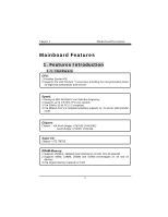
Features 1. Features Introduction 1-1. Hardware 1.Provides Socket-478. 2.Supports the Intel Pentium ® processor providing the new generation power for high-end workstations and servers. 1.Runing at 400/ 533 MHz Front Side Bus frequency. 2.Supports up to 2.8 GHz CPU core speeds. 3.The 33MHz 32 bit - Biostar U8568 PRO | U8568 Pro user's manual - Page 6
Motherboard is equipped with a memory controller providing shadow RAM and support for ROM BIOS. 1.Supports Award BIOS ™ power management functionality. 2.Has a power down timer from 1 to 15 minutes. 1.Contains 1 AGP slot. 2.Contains 1 CNR slot. 3. Contains 5 32-bit PCI bus slots 1.Dual Speed - - Biostar U8568 PRO | U8568 Pro user's manual - Page 7
ADC, DACs. 4.SNR>95 Bb throughmixer and DAC. 1.6CH DAC for AC3®. 2.HRTF-based 3D positional audio, supporting DirectSound™ 3D and A3D™ interface. 3.Supports 4.1/ 5.1 speakers, C3DX positional audio in 4/ 6CH speaker mode. 4.MPU-401 port. 5.Built-in ZV port. 1.OHCI Compliant Programming Interface - Biostar U8568 PRO | U8568 Pro user's manual - Page 8
Serial Bus (USB2.0) Ports and four front panel Universal Serial Bus (USB2.0) Ports. Supports two back panel Universal Serial Bus (USB1.1) Ports and two front panel Universal Serial Bus (USB1.1) Ports. 1.Monitors CPU Fan Speed. 2.Monitors System Voltage. 3.Monitors System Speed. 24.5cm x 29.5cm (WxL - Biostar U8568 PRO | U8568 Pro user's manual - Page 9
1.Award legal BIOS. 2.Supports APM1.2. 3.Supports USB Function. 4.Supports ACPI. Offers the highest performance for MS-DOS, Windows NT, Windows 2000, Windows ME, Windows XP, Novell, LINUX, and SCO UNIX etc. 1-3. Package Contents 1.HDD Cable. 2.FDD Cable. 3.Flash Memory Writer for BIOS Update. 4.USB - Biostar U8568 PRO | U8568 Pro user's manual - Page 10
2. Mainboard Configuration 2-1. Layout of U8568 Pro - Biostar U8568 PRO | U8568 Pro user's manual - Page 11
2-2. Component Index - Biostar U8568 PRO | U8568 Pro user's manual - Page 12
3. CPU Configuration 3-1. CPU Socket 478 Configuration Steps: CPU Fan CPU 1. Pull the lever sideways away from the socket then raise the lever up to a 90-degree angle. 2. Locate Pin A in the socket and look for the white dot or cut edge in the CPU. Match Pin A with the white dot/cut edge then insert - Biostar U8568 PRO | U8568 Pro user's manual - Page 13
CPU Configuration Layout - Biostar U8568 PRO | U8568 Pro user's manual - Page 14
3-2. CPU Fan Header: JCFAN1 Pin No. 1 2 3 Assignment Ground +12V Sense 3-3. System Fan Header: JSFAN1 Pin No. 1 2 3 Assignment Ground +12V Sense - Biostar U8568 PRO | U8568 Pro user's manual - Page 15
4. Jumpers, Headers & Connectors - Biostar U8568 PRO | U8568 Pro user's manual - Page 16
speaker can be connected to the motherboard at the front panel connector. The speaker (onboard or offboard) provides error beep code information during the Power On Self-Test when the computer cannot use the video interface. The speaker is not connected to the audio subsystem and does not receive - Biostar U8568 PRO | U8568 Pro user's manual - Page 17
activity only applies to those IDE drives directly attached to the system board. IR (Infrared Connector) This connector is used to attach to an again. APM (Advanced Power Management) must be enabled in the system BIOS and the APM driver must be loaded. ON/OFF (Power Button) This connector can be - Biostar U8568 PRO | U8568 Pro user's manual - Page 18
must configure the second hard drive on IDE1 to Slave mode by setting the jumper accordingly. • IDE2 (Secondary IDE Connector) The IDE2 controller can also support a Master and a Slave drive. The configuration is similar to IDE1. The second drive on this controller must be set to slave mode. - Biostar U8568 PRO | U8568 Pro user's manual - Page 19
4-4. Floppy Disk Connector: FDD1 The motherboard provides a standard floppy disk connector (FDC) that supports 360K, 720K, 1.2M, 1.44M and 2.88M floppy disk types. This connector supports the provided floppy drive ribbon cables. 4-5. Wake On LAN Header: JWOL1 Pin No. 1 2 3 Assignment +5V SB Ground - Biostar U8568 PRO | U8568 Pro user's manual - Page 20
3. Wait for five seconds. 4. Make JCMOS1 (1-2) closed. 5. Let AC power on. 6. Reset your desired password or clear the CMOS data. 4-7. Front USB Header: JUSB3 (JUSB3) Pin 1 3 5 7 9 Assignment +5V(fused) USBP2USBP2+ Ground KEY Pin Assignment 2 +5V(fused) 4 USBP3- 6 USBP3+ 8 Ground 10 - Biostar U8568 PRO | U8568 Pro user's manual - Page 21
4-10. ATX 12V Power Connector: JATXPWR2 PIN 1 2 Assignment +12V +12V PIN 3 4 Assignment Ground Ground 4-11. 5V / 5VSB Selection for USB: JUSBV1 JUSBV1 Assignment 4-12. 5V / 5VSB Selection for USB: JUSBV3 JUSBV3 Assignment 4-13. 5V / 5VSB Selection for USB: JUSBV4 JUSBV4 Assignment - Biostar U8568 PRO | U8568 Pro user's manual - Page 22
4-14. Front 1394 Header: J1394A1(Optional) Pin Assignment Pin Assignment 1 A+ 2 A- 3 Ground 4 Ground 5 B+ 6 B- 7 +12V 8 +12V 9 KEY 10 Ground 4-15. Front 1394 Header: J1394B1(Optional) Pin Assignment Pin Assignment 1 A+ 2 A- 3 Ground 4 Ground 5 B+ 6 B- 7 + - Biostar U8568 PRO | U8568 Pro user's manual - Page 23
4-17. CNR Codec Primary/Secondary Selection: JCODECSEL Pin No. 1-2 2-3 Assignment On-board Primary Codec CNR Primary Codec - Biostar U8568 PRO | U8568 Pro user's manual - Page 24
5. RAM Module Configuration 5-1. DDR SDRAM DRAM Access Time: 2.5V Unbuffered DDR SDRAM PC1600/ PC2100 Type required. DRAM Type: 128MB/ 256MB/ 512MB/ 1GB DIMM Module (184 pin) Total Memory Size with unbuffer DIMMs - Biostar U8568 PRO | U8568 Pro user's manual - Page 25
you use SDRAM, the memory power will automatically set to 3.3V. !For the above settings, you can only use one kind of memory on this motherboard. It is forbidden to insert both kind of memory simultaneously. You must insert only DDR or SDRAM. - Biostar U8568 PRO | U8568 Pro user's manual - Page 26
How to install DDR/SDRAM DIMM Module 1. The DDR DIMM socket has a " Plastic Safety Tab", and the DDR DIMM memory the slot in one direction 2. Push the tabs out. Insert the DDR DIMM memory modules into the socket at a 90-degree angle, then push down vertically so that it will fit into the place. 3. - Biostar U8568 PRO | U8568 Pro user's manual - Page 27
SDRAM DIMM memory module can only fit into the slot in one direction. 2. Push the tabs out. Insert the SDRAM DIMM memory modules into the socket at a 90-degree angle, then push down vertically so that it will fit into the place. 3. The Mounting Holes and plastic tabs should fit over - Biostar U8568 PRO | U8568 Pro user's manual - Page 28
/2 Keyboard USB COM1 COM2 Speaker Line In Mic Out In JCOM1 JCOM2 JSPKR1 JLIN1 JMIC1 6-1. PS/2 Mouse / Keyboard Connector: JKBMS1 The motherboard provides a standard PS/2 mouse / Keyboard mini DIN connector for attaching a PS/2 mouse. You can plug a PS/2 mouse / Keyboard directly into this - Biostar U8568 PRO | U8568 Pro user's manual - Page 29
6-2. USB & LAN Port Connectors: JUSBLAN1 6-2-1. USB Connectors: USB Connector (the below one) Pin 1 2 3 4 USB Connector (the above one) Pin 5 6 7 8 Assignment +5 V (fused) USBP1USBP1+ Ground Assignment +5 V (fused) USBP2USBP2+ Ground - Biostar U8568 PRO | U8568 Pro user's manual - Page 30
6-2-2. LAN Port Connector (Optional) (only for South Bridge VT8235) This connector allows you to connect to the Internet through a Local Area Network (LAN). You can set up the connection by entering account information provided by your ISP. LAN Port Connector Pin 9 10 11 12 13 14 Assignment VCC3 - Biostar U8568 PRO | U8568 Pro user's manual - Page 31
6-3. Serial and Parallel Interface Ports This system comes equipped with one serial port and one parallel port. Both types of interface ports will be explained in this chapter. 6-3-1. The Serial Interface: JCOM1/ JCOM2 The serial interface port is sometimes referred to as an RS-232 port or an - Biostar U8568 PRO | U8568 Pro user's manual - Page 32
6-3-2. Parallel Interface Port: JPRNT1 Unlike the serial ports, parallel interface port has been standardized and should not present any difficulty interfacing peripherals to your system. Sometimes called centronics port, the parallel port is almost exclusively used with printers. The parallel port - Biostar U8568 PRO | U8568 Pro user's manual - Page 33
edit professional music by connecting MIDI devices. Joystick/MIDI 6-5. Audio Port Connectors: JSPKR1/JLIN1/JMIC1 Speaker Out Line In Mic In or headphones for audio output. 2. Line In can be connected to the external CD player, Tape player or other audio devices for audio input. 3. Mic - Biostar U8568 PRO | U8568 Pro user's manual - Page 34
6-6. Audio Subsystem - Biostar U8568 PRO | U8568 Pro user's manual - Page 35
JCDIN1 Pin No. 1 2 3 4 Assignment Left Channel Input Ground Ground Right Channel Input 6-6-2. Front Panel Audio Header: JAUDIO1 Pin No. Assignment Pin No. Assignment 1 Mic In 2 Ground 3 Mic Power 4 Audio Power 5 RT Line Out 6 RT Line Out 7 Reserved 8 9 LFT Line Out 10 LFT Line - Biostar U8568 PRO | U8568 Pro user's manual - Page 36
a new powerful control utility, features three user-friendly functions including Overclock Manager, Overvoltage Manager, and Hardware Monitor. With the Overclock Manager, users can easily adjust the frequency they prefer or they can get the best CPU performance with just one click. The Overvoltage - Biostar U8568 PRO | U8568 Pro user's manual - Page 37
System Requirement OS Support: Windows 98 SE, Windows Me, Windows 2000, Windows XP DirectX: DirectX 8.1 or above. (The Windows XP operating system includes DirectX 8.1. If you use Windows XP, - Biostar U8568 PRO | U8568 Pro user's manual - Page 38
2. When you see the following dialog in setup procedure, it means setup is completed. If the "Launch the WarpSpeeder Tray Utility" checkbox is checked, the Tray Icon utility and [ WarpSpeeder™ ] utility will be automatically and immediately launched after you click "Finish" button. - Biostar U8568 PRO | U8568 Pro user's manual - Page 39
Usage The following figures are just only for reference, the screen printed in this user manual will change according to your motherboard on hand. [ WarpSpeeder™ ] includes 1 tray icon and 5 panels: 1. Tray Icon: Whenever the Tray Icon utility is launched, it will display a little tray icon on the - Biostar U8568 PRO | U8568 Pro user's manual - Page 40
. Main Panel contains features as follows: a. Display the CPU Speed, CPU external clock, Memory clock, AGP clock, and PCI clock information. b. Contains About, Voltage, Overclock, and Hardware Monitor Buttons for invoking respective panels. c. With a user-friendly Status Animation, it can represent - Biostar U8568 PRO | U8568 Pro user's manual - Page 41
button will be highlighted and the Voltage Panel will slide out to up as the following figure. In this panel, you can decide to increase CPU core voltage and Memory voltage or not. The default setting is "No". If you want to get the best performance of - Biostar U8568 PRO | U8568 Pro user's manual - Page 42
: a. "-3MHz button", "-1MHz button", "+1MHz button", and "+3MHz button": provide user the ability to do real-time overclock adjustment. Warning: Manually overclock is potentially dangerous, especially when the overclocking percentage is over 110 %. We strongly recommend you verify every speed you - Biostar U8568 PRO | U8568 Pro user's manual - Page 43
according to the Recovery Dialog's setting. d. "Verify button": User can click this button and [ WarpSpeeder™ ] will proceed the Recovery Dialog's setting. Note: Because the testing programs, invoked in Auto-overclock and Verify, include DirectDraw, Direct3D and DirectShow tests, the DirectX 8.1 or - Biostar U8568 PRO | U8568 Pro user's manual - Page 44
as the following figure. In this panel, you can get model name and detail information in hints of all the chipset that are related to overclocking. You can also get the mainboard's BIOS model and the Version number of [ WarpSpeeder™ ] utility. - Biostar U8568 PRO | U8568 Pro user's manual - Page 45
- Biostar U8568 PRO | U8568 Pro user's manual - Page 46
Note: Because the overclock, overvoltage, and hardware monitor features are controlled by several separate chipset, [ WarpSpeeder™ ] divide these features to separate panels. If one chipset is not on board, the correlative button in Main panel will be disabled, but will not interfere other panels' - Biostar U8568 PRO | U8568 Pro user's manual - Page 47
- Biostar U8568 PRO | U8568 Pro user's manual - Page 48
-
 1
1 -
 2
2 -
 3
3 -
 4
4 -
 5
5 -
 6
6 -
 7
7 -
8
-
9
-
10
-
11
-
12
-
13
-
14
-
15
-
16
-
17
-
18
-
19
-
20
-
21
-
22
-
23
-
24
-
25
-
26
-
27
-
28
-
29
-
30
-
31
-
32
-
33
-
34
-
35
-
36
-
37
-
38
-
39
-
40
-
41
-
42
-
43
-
44
-
45
-
46
-
47
-
48
 |
 |

±±
±±±
±
²³³±´µ¶·¸¹º»¼·µ±ºµ½±³·¾¿¸¼ÀÁ»
±
±
This equipment has been tested and found to comply with the
limits of a Class B digital device, pursuant to Part 15 of the FCC
Rules. These limits are designed to provide reasonable protection
against harmful interference in a residential installation. This
equipment generates, uses and can radiate radio frequency
energy and, if not installed and used in accordance with the
instructions,
may
cause
harmful
interference
to
radio
communications. There is no guarantee that interference will not
occur in a particular installation.
The vendor makes no representations or warranties with respect
to the contents here of and specially disclaims any implied
warranties
of merchantability or fitness for any purpose. Further
the vendor reserves the right to revise this publication and to
make changes to the contents here of without obligation to notify
any party beforehand.
Duplication of this publication, in part or in whole, is not allowed
without first obtaining the vendor’s approval in writing.
The content of this user’s manual is subject to be changed without
notice and we will not be responsible for any mistakes found in
this user’s manual. All the brand and product names are
trademarks of their respective companies.