Biostar U8768 U8768 user's manual
Biostar U8768 Manual
 |
View all Biostar U8768 manuals
Add to My Manuals
Save this manual to your list of manuals |
Biostar U8768 manual content summary:
- Biostar U8768 | U8768 user's manual - Page 1
energy and, if not installed and used in accordance with the instructions, may cause harmful interference to radio communications. There is no guarantee vendor's approval in writing. The content of this user's manual is subject to be changed without notice and we will not be responsible for any mistakes - Biostar U8768 | U8768 user's manual - Page 2
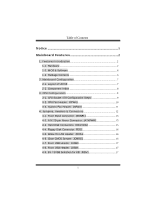
Table of Contents Notice 1 Mainboard Features 2 1. Features Introduction 2 1-1. Hardware...2 1-2. BIOS & Software 6 1-3. Package Contents 6 2. Mainboard Configuration 7 2-1. Layout of U8768 7 2-2. Component Index 8 3. CPU Configuration 9 3-1. CPU Socket 478 Configuration Steps 9 3-2. CPU - Biostar U8768 | U8768 user's manual - Page 3
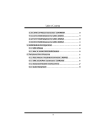
Table of Contents 4-10. ATX 12V Power Connector: JATXPWR2 18 4-11. 5V / 5VSB Selection for USB: JUSBV1 18 4-12. 5V / 5VSB Selection for USB: JUSBV3 18 4-13. 5V / 5VSB Selection for USB: JUSBV4 18 5. RAM Module Configuration 19 5-1. DDR SDRAM 19 5-2. How to install DDR DIMM Module 20 6. - Biostar U8768 | U8768 user's manual - Page 4
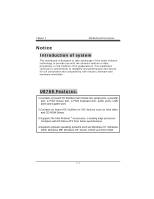
mainboard continues a commitment to reliability and performance and strives for full compliance and compatibility with industry software and hardware standards. U8768 Supports the Intel Pentium ® 4 processor, a leading edge processor. Complies with PC Micro-ATX form factor specifications. 4.Supports - Biostar U8768 | U8768 user's manual - Page 5
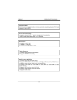
1 Motherboard Description Mainboard Features 1. Features Introduction 1-1. Hardware CPU: 1.Provides Socket-478. 2.Supports the Intel Pentium ® 4 processor providing the new generation power for high-end workstations and servers. Speed: 1.Running at 533 MHz Front Side Bus frequency. 2.Supports up - Biostar U8768 | U8768 user's manual - Page 6
Description Shadow RAM: Motherboard is equipped with a memory controller providing shadow RAM and support for ROM BIOS. Green Functionality: 1.Supports Award BIOS ™ power management functionality. 2.Has a power down timer from 1 to 15 minutes. BUS Slots: 1.Contains 1 AGP slot. 2.Contains - Biostar U8768 | U8768 user's manual - Page 7
Chapter 1 Motherboard Description AC'97 Sound Codec Onboard: 1.AC-LINK protocol comfliance. 2. Capabilities Port (ECP). Normal 2.Supports two serial ports, 16550 UART. 3.Supports Infrared Data Transmission using IrDA. 4.Supports PS/2 mouse and PS/2 keyboard. 5.Supports 360KB, 720KB, 1.2MB, - Biostar U8768 | U8768 user's manual - Page 8
Chapter 1 Dimensions (MATX form-factor): 24.5cm x 22.8cm (WxL) Motherboard Description 1-5 - Biostar U8768 | U8768 user's manual - Page 9
Chapter 1 Motherboard Description 1-2. BIOS & Software 1.Award legal BIOS. 2.Supports APM1.2. 3.Supports USB Function. 4.Supports ACPI. Operating System: Cable. 3.Flash Memory Writer for BIOS Update. 4.USB Cable (Optional). 5.Rear I/O Panel for MATX Case (Optional). 6.Fully Setup Driver CD. 1-6 - Biostar U8768 | U8768 user's manual - Page 10
Chapter 1 Motherboard Description 2. Mainboard Configuration 2-1. Layout of U8768 JKBMS1 K/B & Mouse 1 JKBV1 JUSBLAN1 1 USB & LAN JUSBV1 1 91 9 JUSB3 1 1 JUSBV3 JUSBV4 VT8235 BAT1 24 23 BIOS 1 JCDIN1 PCI SLOT CNR1 CNR SLOT PCI3 21 JPANEL1 ITE I/O JWOL1 1 JCMOS1 1 - Biostar U8768 | U8768 user's manual - Page 11
Chapter 1 Motherboard Description 2-2. Component Index Socket 478 CPU BIOS CMI 9739 VT6103 P4X266E ITE I/O B AT1 VT8235 5V/ 5VSB Selection for USB (JUSBV4) 5V/ 5VSB Selection for USB (JUSBV3) 1-8 - Biostar U8768 | U8768 user's manual - Page 12
Chapter 1 Motherboard Description 3. CPU Configuration 3-1. CPU Socket 478 Configuration Steps: CPU Fan CPU 1. Pull the lever sideways away from the socket then raise the lever up to a - Biostar U8768 | U8768 user's manual - Page 13
Chapter 1 Motherboard Description CPU Configuration Layout Socket 478 CPU P4X266E CMI 9739 VT6103 BAT1 VT8235 BIOS ITE I/O 3-2. CPU Fan Header: JCFAN1 Pin No. 1 2 3 Assignment Ground +12V Sense 1-10 - Biostar U8768 | U8768 user's manual - Page 14
Chapter 1 Motherboard Description 3-3. System Fan Header: JSFAN1 Pin No. 1 2 3 Assignment Ground +12V Sense 1-11 - Biostar U8768 | U8768 user's manual - Page 15
Chapter 1 Motherboard Description 4. Jumpers, Headers & Connectors 1 JKBV1 1 JUSBV1 J AT X P W R 2 2 10 1 9 JUSB3 CMI 1 9739 JUSBV3 VT6103 BIOS Socket 478 CPU J AT X P W R 1 P4X266E IDE1-2 ITE I/O B AT 1 VT8235 JUSB4 2 10 1 9 1 JUSBV4 JPANEL1 JCMOS1 1 FDD1 JWOL1 1 1-12 - Biostar U8768 | U8768 user's manual - Page 16
Connector 23 IRTX 24 IRRX SPK (Speaker Connector) An offboard speaker can be installed on the motherboard as a manufacturing option. An offboard speaker can be connected to the motherboard at the front panel connector. The speaker (onboard or offboard) provides error beep code information - Biostar U8768 | U8768 user's manual - Page 17
Chapter 1 Motherboard Description POW-LED (Power LED Connector) This connector can be the sleep button is depressed again. APM (Advanced Power Management) must be enabled in the system BIOS and the APM driver must be loaded. ON/OFF (Power Button) This connector can be attached to a front panel - Biostar U8768 | U8768 user's manual - Page 18
Chapter 1 Motherboard Description 4-2. Ground Ground -5V 5V 5V 4-3. Hard Disk Connectors: IDE1/IDE2 This mainboard has a 32-bit Enhanced PCI IDE Controller that provides PIO Mode IDE2 (Secondary IDE Connector) The IDE2 controller can also support a Master and a Slave drive. The configuration is - Biostar U8768 | U8768 user's manual - Page 19
motherboard provides a standard floppy disk connector (FDC) that supports 360K, 720K, 1.2M, 1.44M and 2.88M floppy disk types. This connector supports Data The following procedures are for resetting the BIOS password. It is important to follow these instructions closely. ※ Clear CMOS Procedures: 1. - Biostar U8768 | U8768 user's manual - Page 20
Chapter 1 Motherboard Description 3. Wait for five seconds. 4. Make JCMOS1 (1-2) closed. 5. Let AC power on. 6. Reset your desired password or clear the CMOS data. 4-7. Front USB Header: JUSB3 ( - Biostar U8768 | U8768 user's manual - Page 21
Chapter 1 Motherboard Description 4-10. ATX 12V Power Connector: JATXPWR2 PIN 1 2 Assignment 12V 12V PIN 3 4 Assignment Ground Ground 4-11. 5V / 5VSB Selection for USB: JUSBV1 JUSBV1 1 3 1-2 Closed 1 3 2-3 Closed - Biostar U8768 | U8768 user's manual - Page 22
Chapter 1 Motherboard Description 5. RAM Module Configuration 5-1. DDR SDRAM DRAM Access Time: 2.5V Unbuffered DDR SDRAM PC1600/ PC2100 Type required. DRAM Type: 128MB/ 256MB/ 512MB/ 1GB DIMM Module ( - Biostar U8768 | U8768 user's manual - Page 23
Mainboard Features 5-2. How to install DDR DIMM Module Single Sided DIMM Double Sided DIMM 1. The DDR DIMM socket has a " Plastic Safety Tab", and the DDR DIMM - Biostar U8768 | U8768 user's manual - Page 24
Mainboard Features 6. Peripheral Port Features JKBMS1 PS/2 JUSBLAN1 Mouse LAN JPRNT1 Parallel JAUD_GAME Game Port PS/2 Keyboard USB COM1 COM2 Speaker Line In Mic Out In JCOM1 JCOM2 JSPKR1 JLIN1 JMIC1 6-1. PS/2 Mouse / Keyboard Connector: JKBMS1 The motherboard provides a standard PS - Biostar U8768 | U8768 user's manual - Page 25
Mainboard Features 6-2. USB & LAN Port Connectors: JUSBLAN1 6-2-1. USB Connectors: USB Connector (the below one) Pin 1 2 3 4 USB Connector (the above one) Pin 5 6 7 8 Assignment +5 V (fused) USBP1USBP1+ Ground Assignment +5 V (fused) USBP2USBP2+ Ground 22 - Biostar U8768 | U8768 user's manual - Page 26
Mainboard Features 6-2-2. LAN Port Connector This connector allows you to connect to the Internet through a Local Area Network (LAN). You can set up the connection by entering account information provided by your ISP. LAN Port Connector Pin 9 10 11 12 13 14 Assignment VCC3 TD+ TDRD+ RDNC 23 - Biostar U8768 | U8768 user's manual - Page 27
Mainboard Features 6-3. Serial and Parallel Interface Ports This system comes equipped with two serial ports and one parallel port. Both types of interface ports will be - Biostar U8768 | U8768 user's manual - Page 28
Mainboard Features 6-3-2. Parallel Interface Port: JPRNT1 Unlike the serial ports, parallel interface port has been standardized and should not present any difficulty interfacing peripherals to your - Biostar U8768 | U8768 user's manual - Page 29
Mainboard Features 6-4. Game (Joystick/MIDI) Port Connector: JAUD_GAME This connector allows you to connect a joystick or game pad for playing computer games. Also, you may play - Biostar U8768 | U8768 user's manual - Page 30
Mainboard Features four/six channel speakers mode is enabled. 4. Mic In is used to connect a microphone, which allows you to input sounds and voices. 5. Center and - Biostar U8768 | U8768 user's manual - Page 31
6-6. Audio Subsystem Mainboard Features Socket 478 CPU 2 10 1 9 JAUDIO1 CMI 9739 1 JCDIN1 VT6103 BIOS P4X266E BAT1 VT8235 ITE I/O 28 - Biostar U8768 | U8768 user's manual - Page 32
Mainboard Features 6-6-1. CD-ROM Audio-In Header: JCDIN1 Pin No. 1 2 3 4 Assignment Left Channel Input Ground Ground Right Channel Input 6-6-2. Front Panel Audio Header: JAUDIO1 Pin No. - Biostar U8768 | U8768 user's manual - Page 33
06/28/2002
-
 1
1 -
 2
2 -
 3
3 -
 4
4 -
 5
5 -
 6
6 -
 7
7 -
8
-
9
-
10
-
11
-
12
-
13
-
14
-
15
-
16
-
17
-
18
-
19
-
20
-
21
-
22
-
23
-
24
-
25
-
26
-
27
-
28
-
29
-
30
-
31
-
32
-
33
 |
 |

FCC Information and Copyright
This equipment has been tested and found to comply with the
limits of a Class B digital device, pursuant to Part 15 of the FCC
Rules. These limits are designed to provide reasonable protection
against harmful interference in a residential installation. This
equipment generates, uses and can radiate radio frequency
energy and, if not installed and used in accordance with the
instructions,
may
cause
harmful
interference
to
radio
communications. There is no guarantee that interference will not
occur in a particular installation.
The vendor makes no representations or warranties with respect
to the contents here of and specially disclaims any implied
warranties
of merchantability or fitness for any purpose. Further
the vendor reserves the right to revise this publication and to
make changes to the contents here of without obligation to notify
any party beforehand.
Duplication of this publication, in part or in whole, is not allowed
without first obtaining the vendor’s approval in writing.
The content of this user’s manual is subject to be changed without
notice and we will not be responsible for any mistakes found in
this user’s manual. All the brand and product names are
trademarks of their respective companies.