Biostar VIOTECH 3200 Setup Manual
Biostar VIOTECH 3200 Manual
 |
View all Biostar VIOTECH 3200 manuals
Add to My Manuals
Save this manual to your list of manuals |
Biostar VIOTECH 3200 manual content summary:
- Biostar VIOTECH 3200 | Setup Manual - Page 1
Viotech 3200+ Setup Manual FCC Information and Copyright This equipment has been tested and found to comply with the limits of a frequency energy and, if not installed and used in accordance with the instructions, may cause harmful interference to radio communications. There is no guarantee that - Biostar VIOTECH 3200 | Setup Manual - Page 2
Installing System Memory 6 2.4 Connectors and Slots 8 Chapter 3: Headers & Jumpers Setup 11 3.1 How to Setup Jumpers 11 3.2 Detail Settings 11 Chapter 4: Useful Help 15 4.1 Driver Installation Note 15 5.2 Extra Information 16 5.3 Troubleshooting 17 Appendix: SPEC In Other - Biostar VIOTECH 3200 | Setup Manual - Page 3
Viotech 3200+ 1.1 BEFORE YOU START Thank you for choosing our product. Before you start installing the motherboard, please make sure you follow the instructions CHECKLIST Rear I/O Panel Shield X 1 Fully Setup Driver CD X 1 (full version manual files inside) Serial ATA Cable X 2 Quick Installation - Biostar VIOTECH 3200 | Setup Manual - Page 4
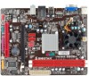
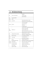
Motherboard Manual 1.3 MOTHERBOARD FEATURES SPEC NanoBGA2 CPU VIA C7-D 1.8G Processor VIA CPU On-board Execute Disable Bit FSB VIA V4 BUS 800MHz Chipset VX900 Graphics Chrome9 HD Max Shared Video Memory is 512MB Support DirectX 9.0 and Pixel Shader (SM2.0) Low Pin Count Interface Super - Biostar VIOTECH 3200 | Setup Manual - Page 5
Port Connector Power Connector (24pin) Power Connector (4pin) PS/2 Keyboard PS/2 Mouse Real Panel VGA Port I/O LAN Port USB Port Audio Jack Board Size 170 (W) x 220 (L) mm OS Support Windows XP / Vista / 7 Viotech 3200+ SPEC x1 Restore CMOS data to factory default x2 Each connector - Biostar VIOTECH 3200 | Setup Manual - Page 6
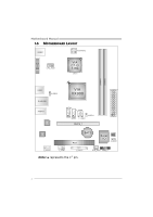
Motherboard Manual 1.5 MOTHERBOARD LAYOUT KBMS1 ATX PW R 2 VGA1 C P U_FA N1 VIA C7-D 1.8G CP U 1 D I MM A 1 D I MM A 2 USB3 J U SB V 2 R J 45U S B1 A U DI O1 LAN VIA VX900 SATA2 F_U S B2 JUSBV1 SATA1 F_USB1 PEX16_1 ATX PW R 1 Codec BAT1 PCI1 Super I/O BIOS J C MOS 1 F_AUDIO1 - Biostar VIOTECH 3200 | Setup Manual - Page 7
Viotech 3200+ CHAPTER 2: HARDWARE INSTALLATION 2.1 INSTALLING CENTRAL PROCESSING UNIT (CPU) The motherboard includes an embedded VIA C7-D or Nano processor, and a heatsink has been installed to provide sufficient cooling. 2.2 FAN HEADERS These fan headers support cooling-fans built in the computer. - Biostar VIOTECH 3200 | Setup Manual - Page 8
DIM MA 1 DIM MA 2 Motherboard Manual 2.3 INSTALLING SYSTEM MEMORY A. DDR3 Module 1. Unlock a DIMM slot by pressing the retaining clips outward. Align a DIMM on the slot such that the notch on the DIMM matches the break - Biostar VIOTECH 3200 | Setup Manual - Page 9
B. Memory Capacity DIMM Socket Location DIMMA1 DIMMA2 DDR3 Module 512MB/1GB/2GB/4GB 512MB/1GB/2GB/4GB Viotech 3200+ Total Memory Size Max is 8GB. 7 - Biostar VIOTECH 3200 | Setup Manual - Page 10
Motherboard Manual 2.4 CONNECTORS AND SLOTS SATA1/SATA2: Serial ATA Connectors The motherboard has a PCI to SATA Controller with 2 channels SATA interface, it satisfies the SATA 2.0 spec and with transfer rate of 3Gb/s. SATA2 SATA1 Pin Assignment 1 Ground 2 TX+ 3 TX- 7 4 Ground 4 5 RX- 6 - Biostar VIOTECH 3200 | Setup Manual - Page 11
Viotech 3200+ ATXPWR1: ATX Power Source Connector This connector allows user to 9 Standby Voltage+5V 10 +12V 11 +12V 12 +3.3V PCI1: Peripheral Component Interconnect Slot The motherboard is equipped with 1 standard PCI slot. PCI stands for Peripheral Component Interconnect, and it is a - Biostar VIOTECH 3200 | Setup Manual - Page 12
Motherboard Manual PEX16_1: PCI-Express x16 Slot - PCI-Express 2.0 compliant (x8-Lane only). - Maximum theoretical realized bandwidth of 4GB/s simultaneously per direction, for an aggregate of 8GB/s totally. PEX16_1 10 - Biostar VIOTECH 3200 | Setup Manual - Page 13
Viotech 3200+ CHAPTER 3: HEADERS & JUMPERS SETUP 3.1 HOW TO SETUP JUMPERS The illustration shows how to set up jumpers. When the jumper cap is placed on pins, the - Biostar VIOTECH 3200 | Setup Manual - Page 14
Motherboard Manual F_USB1/F_USB2: Headers for USB 2.0 Ports at Front Panel This motherboard provides 2 USB 2.0 1 3 Pin 1-2 close 1 3 Pin 2-3 close Note: In order to support this function "Power-On system via USB device," user should place "JUSBV1/ JUSBV2" jumper cap on Pin 2-3 individually. - Biostar VIOTECH 3200 | Setup Manual - Page 15
Viotech 3200+ F_AUDIO1: Front Panel Audio Header This header allows user to connect the front audio output cable with the PC front panel. 2 allows user to restore the BIOS safe setting and the CMOS data. Please carefully follow the procedures to avoid damaging the motherboard. 13 Pin 1-2 Close: - Biostar VIOTECH 3200 | Setup Manual - Page 16
Motherboard Manual J_COM1: Serial port Connector The motherboard has a Serial Port Connector for connecting RS-232 Port. Pin 1 2 3 4 5 6 7 2 10 8 9 10 1 9 J_PRINT1: Printer Port Connector This header allows you to connector printer on the - Biostar VIOTECH 3200 | Setup Manual - Page 17
USEFUL HELP Viotech 3200+ 4.1 DRIVER INSTALLATION NOTE After you installed your operating system, please insert the Fully Setup Driver CD into your optical drive and install the driver for better system performance. You will see the following window after you insert the CD The setup guide will - Biostar VIOTECH 3200 | Setup Manual - Page 18
Motherboard Manual 5.2 EXTRA INFORMATION CPU Overheated If the system shutdown automatically after power on system for minutes, that means the CPU protection function has been activated. When the CPU is over heated, the motherboard will shutdown automatically to avoid a damage of the CPU, and the - Biostar VIOTECH 3200 | Setup Manual - Page 19
Viotech 3200+ 5.3 TROUBLESHOOTING Replace cable. 3. Contact technical support. System is inoperative. Keyboard 2. Check cable running from disk to disk controller board. Make sure both ends are securely plugged in Configuration" or "CMOS Failure." Review system's equipment. Make sure correct - Biostar VIOTECH 3200 | Setup Manual - Page 20
Motherboard Manual APPENDIX: SPEC IN OTHER LANGUAGES GERMAN Spezifikationen CPU VIA C7-D 1.8G CPU FSB Chipsatz Grafik VIA V4 BUS 800MHz VX900 Chrome9 HD NanoBGA2 VIA CPU On-board Execute Disable Bit Max. 512MB gemeinsam benutzter Videospeicher Super E/A ITE 8728 Low Pin Count-Schnittstelle - Biostar VIOTECH 3200 | Setup Manual - Page 21
(4-polig) PS/2-Tastatur PS/2-Maus Rückseiten-E VGA-Anschluss /A LAN-Anschluss USB-Anschluss Audioanschluss Platinengröße 170 mm (B) X 220 mm (L) OS-Unterstüt Windows XP / Vista / 7 zung Spezifikationen Viotech 3200+ x1 System-Lüfter-Stromversorgungsanschluss x1 Jeder Anschluss unterst - Biostar VIOTECH 3200 | Setup Manual - Page 22
Motherboard Manual FRENCH SPEC NanoBGA2 UC VIA C7-D 1.8G CPU VIA CPU On-board d'exécution de bit de désactivation Bus frontal VIA V4 BUS 800MHz Chipset VX900 Graphiques Chrome9 HD Mémoire vidéo partagée maximale de 512 Mo Interface à faible compte de broches Super E/S ITE 8728 - Biostar VIOTECH 3200 | Setup Manual - Page 23
Clavier PS/2 x1 Souris PS/2 x1 E/S du Port VGA x1 panneau Port LAN x1 arrière Port USB x4 Fiche audio x3 Dimensions 170mm (l) X 220 mm (H) de la carte Support SE Windows XP / Vista / 7 Biostar se réserve le droit d'ajouter ou de supprimer le support de SE avec ou sans préavis. 21 - Biostar VIOTECH 3200 | Setup Manual - Page 24
Motherboard Manual ITALIAN SPECIFICA NanoBGA2 CPU VIA C7-D 1.8G CPU VIA CPU On-board Execute Disable Bit FSB VIA V4 BUS 800MHz Chipset VX900 Grafica Chrome9 HD La memoria video condivisa massima è di 512MB Interfaccia LPC (Low Pin Count) Super I/O ITE 8728 Funzioni di controllo dell' - Biostar VIOTECH 3200 | Setup Manual - Page 25
SPECIFICA Viotech 3200+ Collettore cancellaz ione CMOS x1 Connettore USB Ciascun connettore VGA x1 pannello Porta LAN x1 posteriore Porta USB x4 Connettore audio x3 Dimension 170 mm (larghezza) x 220 mm i scheda (altezza) Sistemi operativi Windows XP / Vista / 7 supportati Biostar - Biostar VIOTECH 3200 | Setup Manual - Page 26
Motherboard Manual SPANISH Especificación NanoBGA2 CPU VIA C7-D 1.8G CPU VIA CPU On-board Bit de deshabilitación de ejecución FSB VIA V4 BUS 800MHz Conjunto de VX900 chips Gráficos Chrome9 HD Memoria máxima de vídeo compartida de 512MB Interfaz de cuenta Low Pin Súper E/S ITE 8728 - Biostar VIOTECH 3200 | Setup Manual - Page 27
(A) X 220 mm. (H) la placa Soporte de sistema Windows XP / Vista / 7 operativo Especificación Viotech 3200+ X1 X2 Cada conector soporta 2 puertos USB frontales X1 Cada conector soporta 1 Puerto de impresora X1 X1 X1 X1 X1 X1 X1 X4 X3 Biostar se reserva el derecho de añadir o retirar el - Biostar VIOTECH 3200 | Setup Manual - Page 28
Motherboard Manual PORTUGUESE ESPECIFICAÇÕES NanoBGA2 CPU VIA C7-D 1.8G CPU VIA CPU On-board Execute Disable Bit FSB VIA V4 BUS 800MHz Chipset VX900 Placa gráfica Chrome9 HD Memória de vídeo máxima partilhada: 512 MB Interface LPC (Low Pin Count) Especificaçã ITE 8728 o Super I/O - Biostar VIOTECH 3200 | Setup Manual - Page 29
ESPECIFICAÇÕES Viotech 3200+ Conector da ventoinha da CPU x1 Alimentação da ventoinha da aídas no Porta VGA x1 painel Porta LAN x1 traseiro Porta USB x4 Tomada de audio x3 Tamanho da placa 170 mm (L) X 220 mm (A) Sistemas operativos Windows XP / Vista / 7 A Biostar reserva-se o direito - Biostar VIOTECH 3200 | Setup Manual - Page 30
Motherboard Manual POLISH SPEC NanoBGA2 Procesor VIA C7-D 1.8G CPU VIA CPU On-board Execute Disable Bit FSB VIA V4 BUS 800MHz Chipset VX900 Grafika Chrome9 HD Maks. wielkość współdzielonej pamięci video wynosi 512MB Każde gniazdo DIMM obsługuje moduły 512MB/1GB/2GB/4GB DDR3 Pamięć głó - Biostar VIOTECH 3200 | Setup Manual - Page 31
Viotech 3200+ SPEC Złącze główkowe wentylatora procesora Zasilanie wentylatora procesora x1 Złącze głó Panel Port VGA x1 I/O Port LAN x1 Port USB x4 Gniazdo audio x3 Wymiary płyty 170 mm (S) X 220 mm (W) Obsluga systemu Windows XP / Vista / 7 operacyjne go Biostar zastrzega sobie prawo - Biostar VIOTECH 3200 | Setup Manual - Page 32
Motherboard Manual RUSSIAN СПЕЦ CPU VIA C7-D 1.8G CPU ый NanoBGA2 VIA CPU On-board Execute Disable Bit FSB VIA V4 BUS 800МГц Набор VX900 Chrome9 HD DDR3 DIMM x 2 память Super I/O ITE 8728 SATA ATA 512 DIMM 512МБ/1ГБ/2ГБ/4ГБ DDR3 8 DDR3 800 / 1066 DDR3 DIMM and ECC - Biostar VIOTECH 3200 | Setup Manual - Page 33
Viotech 3200+ СПЕЦ x1 x1 CMOS x1 USB 2 USB x2 1 x1 x1 24 вывод) x1 4 вывод) x1 PS/2 x1 Задняя Мышь PS/2 x1 панель Порт VGA x1 LAN x1 USB-порт x4 ода x3 170 мм (Ш) X 220 мм (В) Windows XP / - Biostar VIOTECH 3200 | Setup Manual - Page 34
Motherboard Manual ARABIC NanoBGA2 VIA CPU On-board Execute Disable Bit 512 512 /1 DDR3 DIMM و /2و 4 8 800 / 1066 DDR3 DDR3 ECC DIMM Low Pin Count Interface 3 2.0 SATA 100/10 5.1 1 1 SATA 2 1 1 32 VIA C7-D 1.8G CPU VIA V4 - Biostar VIOTECH 3200 | Setup Manual - Page 35
Viotech 3200+ 1 1 1 CMOS 2 USB USB 1 1 1 24 1 4 1 PS/2 1 PS/2 1 VGA 1 4 USB 3 170 220 X Biostar Windows XP / Vista / 7 33 - Biostar VIOTECH 3200 | Setup Manual - Page 36
Motherboard Manual JAPANESE CPU VIA C7-D 1.8G CPU FSB VIA V4 BUS 800MHz VX900 Chrome9 HD ス DDR3 DIMM x 2 Super I/O ITE 8728 SATA ATA LAN Realtek RTL8103EL Codec VIA VT1708S スロット PCI PCI Express Gen2 x16スロット SATAコネクタ ネクタ CPU 34 仕様 NanoBGA2 VIA CPU On-board - Biostar VIOTECH 3200 | Setup Manual - Page 37
Viotech 3200+ 仕様 x1 CMOS x1 USBコネクタ 2 USB x2 ます x1 1 x1 24ピン) x1 4ピン) x1 PS/2 x1 PS/2マウス x1 VGAポート x1 I/O LANポート x1 USBポート x4 x3 170 mm (幅) X 220 mm (高さ) OS Windows XP / Vista / 7 Biostar OS 2011/05/03 35
-
 1
1 -
 2
2 -
 3
3 -
 4
4 -
 5
5 -
 6
6 -
 7
7 -
8
-
9
-
10
-
11
-
12
-
13
-
14
-
15
-
16
-
17
-
18
-
19
-
20
-
21
-
22
-
23
-
24
-
25
-
26
-
27
-
28
-
29
-
30
-
31
-
32
-
33
-
34
-
35
-
36
-
37
 |
 |

Viotech 3200+ Setup Manual
FCC Information and Copyright
This equipment has been tested and found to comply with the limits of a Class
B digital device, pursuant to Part 15 of the FCC Rules. These limits are designed
to provide reasonable protection against harmful interference in a residential
installation. This equipment generates, uses, and can radiate radio frequency
energy and, if not installed and used in accordance with the instructions, may
cause harmful interference to radio communications. There is no guarantee
that interference will not occur in a particular installation.
The vendor makes no representations or warranties with respect to the
contents here and specially disclaims any implied warranties of merchantability
or fitness for any purpose. Further the vendor reserves the right to revise this
publication and to make changes to the contents here without obligation to
notify any party beforehand.
Duplication of this publication, in part or in whole, is not allowed without first
obtaining the vendor’s approval in writing.
The content of this user’s manual is subject to be changed without notice and
we will not be responsible for any mistakes found in this user’s manual. All the
brand and product names are trademarks of their respective companies.