Bosch 1619EVS Operating Instructions - Page 11
FIG. 10, FIG. 11
 |
UPC - 000346313222
View all Bosch 1619EVS manuals
Add to My Manuals
Save this manual to your list of manuals |
Page 11 highlights
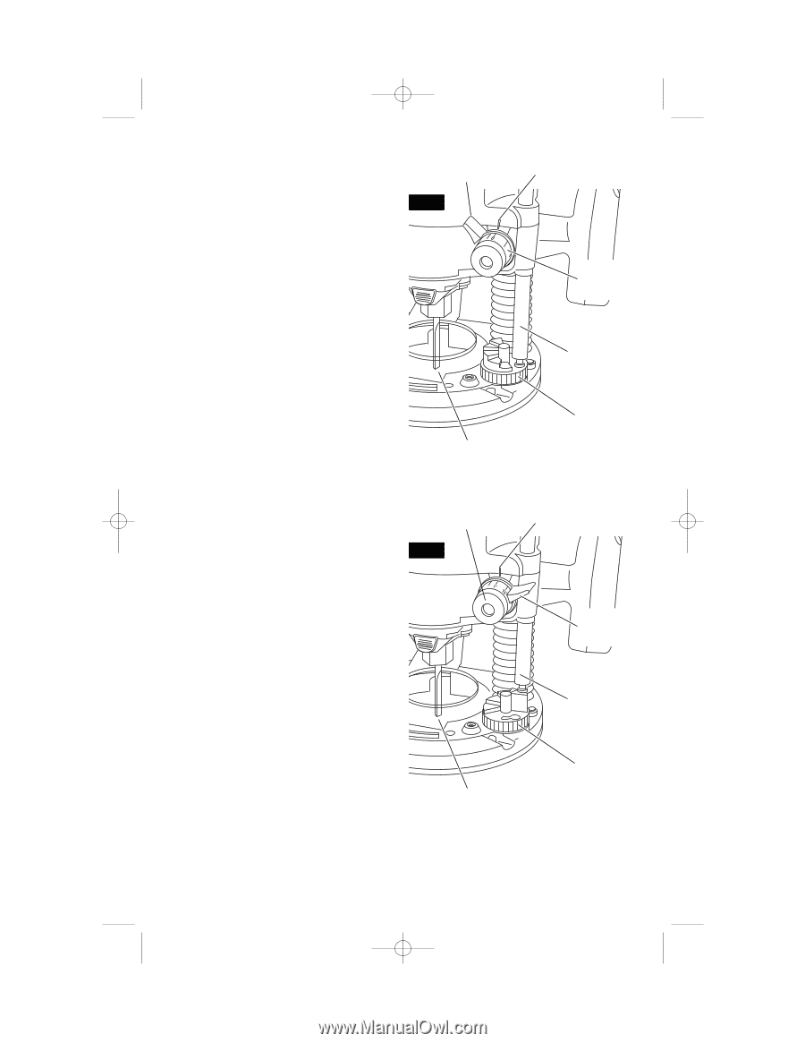
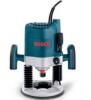
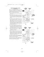
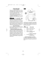
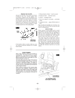
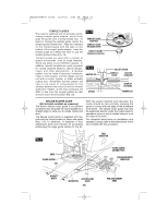
BM2610995777 10/03 10/7/03 4:51 PM Page 11 MAKING PROGESSIVELY DEEPER PLUNGE CUTS When making deep cuts, especially slot cuts away from the edge of the workpiece, it is advisable to make several successive cuts using the depth stop turret's six 1/8" steps, rather than making a single deep cut: 1. Align the lowest step of turret with the depth rod. (Fig. 10) 2. With the bit installed, gently lower the motor until router bit just contacts the level surface the router is sitting on. Release the plunge lock lever, locking the motor at this position. (Fig. 10) 3. Loosen the coarse adjustment lock and lower the depth rod until it contacts the lowest step on the turret. Turn the coarse depth indicator until zero lines up with the reference mark. This is the "zero" position, which indicates the point at which the bit just contacts the workpiece. Release the plunge lock lever and allow the motor to return to its normal position. (Fig. 10) 4. To set the desired total cutting depth, turn the coarse adjustment knob counterclockwise as close as possible to the desired cutting depth, and secure the rod by turning the coarse adjustment lock to the right and press down firmly (Fig. 11). Make any necessary refinements with the fine adjustment knob (Fig. 9). 5. Align the top step of the turret with the depth rod, and make the first cut pass in the workpiece. After each pass, rotate the depth stop turret to the next lower step and make another pass as necessary until the desired final depth is reached. (Fig. 11) The router's Precision Centering Design helps to ensure that each successive pass with follow the same cut as previous passes. To be certain that your depth settings are as desired, you may want to make test cuts in scrap material before beginning work. COARSE ADJUSTMENT LOCK FIG. 10 BIT COARSE ADJUSTMENT KNOB FIG. 11 REFERENCE MARK COARSE ADJUSTMENT INDICATOR DEPTH ROD DEPTH STOP TURRET REFERENCE MARK COARSE ADJUSTMENT LOCK DEPTH ROD DEPTH STOP TURRET BIT -11-
-
 1
1 -
2
-
3
-
4
-
5
-
 6
6 -
 7
7 -
 8
8 -
 9
9 -
 10
10 -
 11
11 -
 12
12 -
 13
13 -
 14
14 -
 15
15 -
 16
16 -
17
-
18
-
19
-
20
-
21
-
22
-
23
-
24
-
25
-
26
-
27
-
28
-
29
-
30
-
31
-
32
-
33
-
34
-
35
-
36
-
37
-
38
-
39
-
40
-
41
-
42
-
43
-
44
-
45
-
46
-
47
-
48
-
49
-
50
-
51
-
52
-
53
-
54
-
55
-
56
 |
 |