Bosch 1619EVS Operating Instructions - Page 12
Warning
 |
UPC - 000346313222
View all Bosch 1619EVS manuals
Add to My Manuals
Save this manual to your list of manuals |
Page 12 highlights
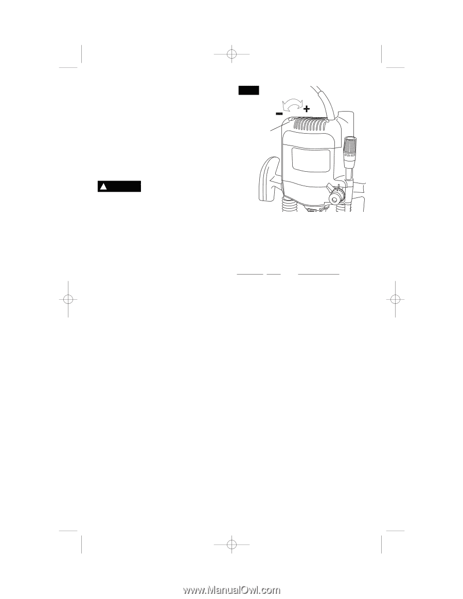
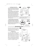
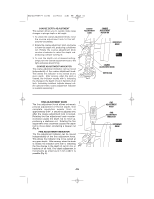
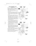
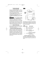
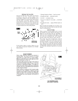
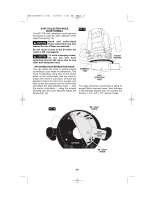
BM2610995777 10/03 10/7/03 4:51 PM Page 12 TRIGGER SWITCH AND "LOCK-ON" BUTTON Your router can be turned ON or OFF by squeezing or releasing the trigger. Your router is also equipped with a "Lock-ON" button located to the left of trigger that allows continuous operation without holding the trigger. TO LOCK SWITCH ON: Squeeze trigger, depress button and release trigger (Fig. 2). TO UNLOCK THE SWITCH: Squeeze trigger and release it without depressing the "Lock-ON" button. ! WARNING If the "Lock-ON" button is continuously being depressed, the trigger cannot be released. Always make sure that the bit is not touching the work when turning the switch on or off. Contact the work with the router after the router has reached full speed, and remove it from the work before turning the switch off. Operating in this manner will prolong switch and motor life and will greatly increase the quality of your work. SOFT START FEATURE Electronic feedback control minimizes torque twist customary in larger routers by limiting the speed at which motor starts. ELECTRONIC VARIABLE SPEED CONTROL The electronic speed control feature allows motor speed to be matched to cutter size and material hardness for improved finish, extended bit life, and higher performance. Speed changes are achieved by rotating Speed Control Dial FORWARD to decrease speed, BACK to increase speed, as indicated on housing (Fig. 12). Speed may be changed while tool is on. The reference numbers on the dial facilitate re-setting control to desired speed. FIG. 12 SPEED CONTROL DIAL The speed chart indicates the relationship between settings and application. Exact settings are determined by operator experience and preference. The bit manufacturer may also have a speed recommendation. DIAL SETTING RPM APPLICATION 1 2 } 8,000 9,000 Large diameter bits (Raised Panel) 3 11,000 4 5 } 13,000 17,000 Hardwood, Non-ferrous metals, soft Plastics Softwoods, counter tops, 6 } 21,000 Smaller dia. router bits, Hard plastics, Decorative Edges CONSTANT RESPONSE™ CIRCUITRY The router's Constant Response™ Circuitry monitors and adjusts power to maintain the desired RPM for consistent performance and control. -12-
-
 1
1 -
2
-
3
-
4
-
5
-
6
-
 7
7 -
 8
8 -
 9
9 -
 10
10 -
 11
11 -
 12
12 -
 13
13 -
 14
14 -
 15
15 -
 16
16 -
 17
17 -
18
-
19
-
20
-
21
-
22
-
23
-
24
-
25
-
26
-
27
-
28
-
29
-
30
-
31
-
32
-
33
-
34
-
35
-
36
-
37
-
38
-
39
-
40
-
41
-
42
-
43
-
44
-
45
-
46
-
47
-
48
-
49
-
50
-
51
-
52
-
53
-
54
-
55
-
56
 |
 |