Bosch 1619EVS Operating Instructions - Page 15
FIG. 18, FIG. 17 - router table
 |
UPC - 000346313222
View all Bosch 1619EVS manuals
Add to My Manuals
Save this manual to your list of manuals |
Page 15 highlights
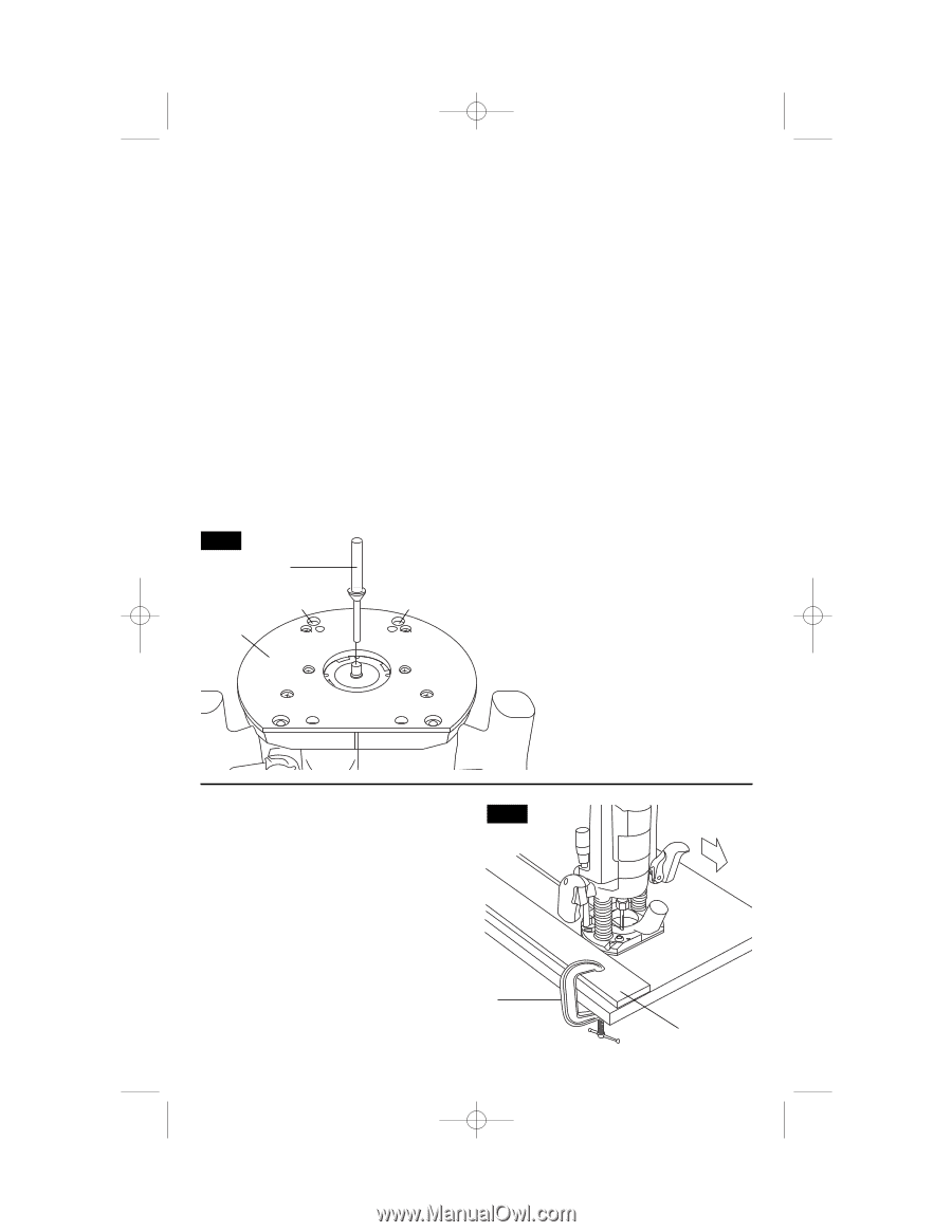
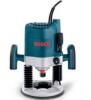
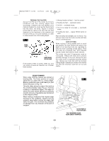
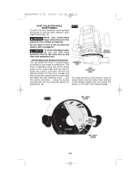
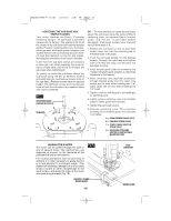
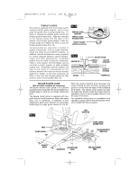
BM2610995777 10/03 10/7/03 4:51 PM Page 15 CENTERING THE SUB-BASE AND TEMPLET GUIDES Your router features the Bosch "Precision Centering Design". Its sub-base is precisely centered at the factory. This positions the bit at the center of the sub-base and optional templet guides. Precision centering allows you to closely follow jigs such as straight guides, templets, and dovetail fixtures without worrying about bit walkoff from the intended cut line for any reason, including the orientation of the router's handles. In the event the sub-base screws are loosened or removed, such when preparing the router for use in a router table, here's how to re-center the sub-base when reattaching it: To quickly re-center the sub-base, attach the sub-base using the set of flathead screws (included) and the countersunk screw holes in the sub-base. (Flathead screws have the tapered heads.) The flathead screws and countersunk holes will pull the sub-base into a position that is very close to centered. FIG. 17 CENTERING CONE (optional accessory) SUB-BASE B 1 AD C A B D B DA C A D B OR - To most precisely re-center the sub-base, attach the sub-base using the optional Bosch centering cone, an optional Bosch templet guide, and the set of pan-head screws (included). (Pan-head screws have rounded tops.) Follow steps 1-8. 1. Position the sub-base so that its pan-head screw holes are over the matching set of threaded holes in the base. 2. Insert the pan-head screws, not the flathead screws, through the sub-base and tighten them until they are snug, but still allow the sub-base to move. 3. Insert templet guide (optional accessory) the installed template guide adapter as described elsewhere in this manual. 4. Slide centering cone (optional accessory) through templet guide and into collet. Use narrow end of cone when inserting into 1/4" collet, wider end of cone when inserting into 1/2" collet. 5. Tighten collet nut with fingers to put slight grip on centering cone. 6. Lightly press centering cone into templet guide to center guide and sub-base. 7. Tighten the pan-head screws. 8. Remove centering cone. The precision centering of the templet guide and sub-base is complete. A = COUNTERSUNK SCREW HOLES B = PAN-HEAD SCREW HOLES C = TEMPLET GUIDE ADAPTER SCREW HOLES D = HOLES FOR ATTACHING ROUTER TO ROUTER TABLE MOUNTING PLATE GUIDING THE ROUTER The router can be guided through the work in any of several ways. The method you use depends, of course, on the demands of the particular job and on convenience. For routing operations such as grooving or dadoing, it is often necessary to guide the tool in a line parallel to a straight edge. One method of obtaining a straight cut is to securely clamp a board or other straightedge to the work surface, and guide the edge of the router sub-base along this path (Fig. 18). FIG. 18 SECURELY CLAMP BOARD GUIDE -15- FEED DIRECTION BOARD GUIDE
-
 1
1 -
2
-
3
-
4
-
5
-
6
-
7
-
8
-
9
-
 10
10 -
 11
11 -
 12
12 -
 13
13 -
 14
14 -
 15
15 -
 16
16 -
 17
17 -
 18
18 -
 19
19 -
 20
20 -
21
-
22
-
23
-
24
-
25
-
26
-
27
-
28
-
29
-
30
-
31
-
32
-
33
-
34
-
35
-
36
-
37
-
38
-
39
-
40
-
41
-
42
-
43
-
44
-
45
-
46
-
47
-
48
-
49
-
50
-
51
-
52
-
53
-
54
-
55
-
56
 |
 |