Bosch LTC 5136/61 Instruction Manual
Bosch LTC 5136/61 Manual
 |
View all Bosch LTC 5136/61 manuals
Add to My Manuals
Save this manual to your list of manuals |
Bosch LTC 5136/61 manual content summary:
- Bosch LTC 5136/61 | Instruction Manual - Page 1
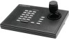
LTC 5136 Series Instruction Manual EN AutoDome® Controller - Bosch LTC 5136/61 | Instruction Manual - Page 2
LTC 5136 Series | Instruction Manual | Important Safeguards EN | 2 Important Safeguards 1. Read Instructions - All safety and operating instructions should be read before the unit is operated. 2. Retain Instructions - The safety and operating instructions National Electrical Code Article 820 - Bosch LTC 5136/61 | Instruction Manual - Page 3
LTC 5136 Series | Instruction Manual | FCC Information EN | 3 17. Damage Requiring Service - Unplug the unit from the outlet and refer servicing to qualified service personnel under the following conditions: a. When the power supply cord or plug is damaged. b. If liquid has been spilled or objects - Bosch LTC 5136/61 | Instruction Manual - Page 4
LTC 5136 Series | Instruction Manual | Safety Precautions Safety Precautions Sécurité EN | 4 CAUTION: TO REDUCE THE RISK OF ELECTRIC SHOCK, DO NOT REMOVE COVER (OR BACK). NO USER SERVICEABLE PARTS INSIDE. REFER SERVICING TO QUALIFIED SERVICE du code Bosch Security Systems | 04 September 2003 - Bosch LTC 5136/61 | Instruction Manual - Page 5
LTC 5136 Series | Instruction Manual | Safety Precautions Sicherheitshinweise Precauciones de nur von qualifiziertem Wartungspersonal gemäß dem National Electrical Code oder den gültigen örtlichen Vorschriften durchgeführt werden desconexión del equipo. Bosch Security Systems | 04 September 2003 - Bosch LTC 5136/61 | Instruction Manual - Page 6
LTC 5136 Series | Instruction Manual | Safety Precautions Veiligheidsmaatregelen Sicurezza waarschuwen voor de aanwezigheid van belangrijke bedieningsen onderhouds- (service-) instructies in de documentatie die met het product zijn tutti gli apparecchi. Bosch Security Systems | 04 September 2003 - Bosch LTC 5136/61 | Instruction Manual - Page 7
LTC 5136 Series | Instruction Manual | Safety Precautions Medidas de Segurança Zasady Bezpiecze de assistência técnica qualificado, de acordo com o National Electrical Code (Normas de Electricidade Nacionais) ou a legislação local aplicável ów urządzeń. Bosch Security Systems | 04 September 2003 - Bosch LTC 5136/61 | Instruction Manual - Page 8
LTC 5136 Series | Instruction Manual | Contents EN | 8 Table of Contents Important Safeguards 2 FCC Information 2 1 UNPACKING 9 2 SERVICE 9 3 DESCRIPTION 9 3.1 Power 9 4 INSTALLATION 10 4.1 General 10 4.2 Installation using Biphase Code 10 4.3 Installation using RS-232 Data Direct to - Bosch LTC 5136/61 | Instruction Manual - Page 9
and shipping instructions. 3 DESCRIPTION The LTC 5136 Series Controllers are designed for use with the Bosch AutoDome Series cameras. They can also be used to operate any of the conventional Allegiant® Series of Receiver/Drivers. The LTC 5136 Series controllers support control of all AutoDome and - Bosch LTC 5136/61 | Instruction Manual - Page 10
LTC 5136 Series | Instruction Manual | Installation EN | 10 4 INSTALLATION 4.1 General The desktop Controller unit should be installed in a location convenient to the operator. The Controller contains a single RJ-11 connector, which is used for both power and data connections. In most applications - Bosch LTC 5136/61 | Instruction Manual - Page 11
LTC 5136 Series | Instruction Manual | Installation EN | 11 Pin 1 Pin 6 Figure 1 Interface Unit Supplied with LTC 5136 The removable terminal blocks have three connections: (+), (-), and (S [Shield]), as shown in the diagram above. Select and maintain a wire color convention to avoid confusion at - Bosch LTC 5136/61 | Instruction Manual - Page 12
LTC 5136 Series | Instruction Manual | Installation EN | 12 4.4 Installation Using an RS-232 Data Transmission Link to a Biphase Camera Site (See Figure 6) In this application, the RS-232 data that is generated by the Controller is connected directly to an RS-232 transmission link (fiber optics, - Bosch LTC 5136/61 | Instruction Manual - Page 13
LTC 5136 Series | Instruction Manual | Setting Fast Addess Feature EN | 13 4.5 AutoDome Camera or Receiver/Driver Site Configuration Follow the standard installation instructions provided with the AutoDome Camera or Allegiant Series Receiver/Driver unit to connect the data cable to the unit. Set - Bosch LTC 5136/61 | Instruction Manual - Page 14
LTC 5136 Series | Instruction Manual | Controller Operation EN | 14 5. Press ON-1-ENTER and the address display a unique code number associated with that key. Use the table below to ensure that all keys are operating properly. Push the USER key last, as this will cause the Controller to exit the - Bosch LTC 5136/61 | Instruction Manual - Page 15
LTC 5136 Series | Instruction Manual | Controller Operation EN | 15 CAMERA key: This key is only used to correct an error when selecting a camera number. If another key is inadvertently pressed when a camera selection is being made, the Camera button may be pressed to put the Controller - Bosch LTC 5136/61 | Instruction Manual - Page 16
LTC 5136 Series | Instruction Manual | Technical Reference 7 TECHNICAL REFERENCE EN | 16 Video Monitor DVR or Video Switcher Data Converter Unit Power Supply Adapter Video Signal Up to 16 biphase control code outputs RS-232 Data & Power Controller Figure 3 Typical Camera Site Using Biphase - Bosch LTC 5136/61 | Instruction Manual - Page 17
LTC 5136 Series | Instruction Manual | Technical Reference EN | 17 Video Monitor Power Supply Adapter Video Signal Controller RS-232 Data & Power LTC 8557 Junction Box RS-232 Cable or Communication Link Typical AutoDome Camera or Allegiant Receiver/Driver unit Figure 5 Typical Installation - Bosch LTC 5136/61 | Instruction Manual - Page 18
LTC 5136 Series | Instruction Manual | Technical Reference Pin 6 Pin 1 Figure 7 Supplied 6-Conductor 3 m (10 ft) Data Cable Detail EN | 18 Pin 1 Pin 6 Connector Pinouts: 1. 12V 2. Not used 3. Rx (Not used) 4. Tx 5. Signal Ground 6. 12V Pin 6 Figure 8 Rear Panel Controller Connector Detail Pin 1 - Bosch LTC 5136/61 | Instruction Manual - Page 19
LTC 5136 Series | Instruction Manual | Data Converter Pinouts 8 DATA CONVERTER PINOUTS Data In - 9-Pin Connector (Male) Pin Connection 1 No Connection 1 Output Voltage 2 Signal Ground 3 Rx 4 Ground 5 No Connection 6 Output Voltage EN | 19 Bosch Security Systems | 04 September 2003 - Bosch LTC 5136/61 | Instruction Manual - Page 20
Lancaster, PA 17601 EE.UU. Tel: 800-326-3270 Fax: 1-717-735-6560 www.boschsecuritysystems.com Robert Bosch GmbH Geschäftsbereich Postfach 10 60 50 70049 Stuttgart Telefax (0711) 8 11-12 34 Bosch Security Systems B.V. P.O. Box 80002 5600 JB Eindhoven The Netherlands Tele +31 40 27 80000 © 2003
-
 1
1 -
 2
2 -
 3
3 -
 4
4 -
 5
5 -
 6
6 -
 7
7 -
8
-
9
-
10
-
11
-
12
-
13
-
14
-
15
-
16
-
17
-
18
-
19
-
20
 |
 |

LTC 5136 Series
Instruction Manual
EN
AutoDome
®
Controller