Bosch VC7C1305T Installation Instructions - Page 7
Video Recorder in/output, 2.5 Alarm output contact N.O./N.C., 2.6 RS232, 2.7 Mains Power
 |
View all Bosch VC7C1305T manuals
Add to My Manuals
Save this manual to your list of manuals |
Page 7 highlights
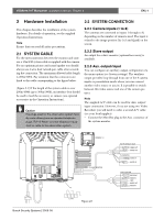
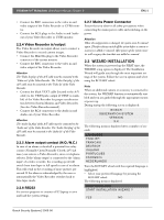
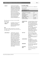
VSS8394/01T Multiplexer | Installation Manual | Chapter 2 EN | 5 • Connect the BNC connectors to the video in and video output of the Video Recorder or CVBS monitor. • Connect the RCA plugs to the Audio in and Audio out of your Video Recorder or CVBS monitor. 2.2.4 Video Recorder in/output The Video Recorder in/output allows you to connect a Video Recorder to record camera images. • Connect the Mini Din plug to the Video Recorder connector of the system monitor. • Connect the BNC connectors to the video in and video output of the Video Recorder. Attention The 'Video In plug' of the A/V cable must be connected to the 'Video out' of the Video Recorder. The 'Video Out plug' of the A/V cable must be connected to the 'Video In' of the Video Recorder. • Connect the black VEXT cable (located in the A/V cable) to the VEXT-pulse output (if VEXT is available) of the Video Recorder for proper synchronization between System Monitor and Video Recorder. (See also Video Recorder manual). • Connect the RCA connectors to the Audio in and Audio out of your Video Recorder. Attention The 'Audio In plug' of the A/V cable must be connected to the 'Audio out' of the Video Recorder. The 'Audio Out plug' of the A/V cable must be connected to the 'Audio In' of the Video Recorder. 2.2.5 Alarm output contact (N.O./N.C.) In case of an alarm or doorbell a potential free relay contact (Normally Open/Normally Closed; 24V/2A max.) can activate a Video Recorder, siren or telephone selector. If the 'alarm output' is connected to the 'alarm input' of a video recorder, the recording speed will switch from time-lapse to full speed in case of an alarm. This will result in the recording of more pictures per second. If the alarm is acknowledged by the user or automatically the Video Recorder switches back to time-lapse mode. 2.2.6 RS232 For service purposes to connect a PC/Laptop to save and load the system settings. 2.2.7 Mains Power Connector Ensure that you observe all safety precautions when connecting the mains power cable and switching on the power. Attention When the configuration is changed, the system must be scanned again. Therefore always switch off the system before a camera or accessory is added or removed. After power up the system monitor will recognize the item that was added or removed. 2.3 WIZARD INSTALLATION When the system is powered up the FIRST time, the WIZARD setup option is displayed. The Installation Wizard will guide you through the most important settings of the system. Follow the screen options and select using the ROTARY wheel. Note When an additional camera or accessory is connected to the system, the WIZARD function is automatically enabled and you are guided through the appropriate menus at power up. During startup the following screen is displayed: BOSCH O B S E RVATI O N SYSTE M VERSION X.X The following menu is displayed after a number of seconds: LANGUAGE ENGLISH FRANCAIS DEUTSCH ITALIAN O PORTUGUES ESPAG NOL NEDERLANDS Turn the ROTARY wheel until the required language is highlighted. • Select your preferred language by pressing the ROTARY wheel. The following menu is displayed: CON F IG U RATION START I N STALLATI O N W I Z AR D ? YES NO Bosch Security Systems | 2003-06
-
 1
1 -
 2
2 -
 3
3 -
 4
4 -
 5
5 -
 6
6 -
 7
7 -
 8
8 -
 9
9 -
 10
10 -
 11
11 -
 12
12 -
13
-
14
-
15
-
16
-
17
-
18
-
19
-
20
-
21
-
22
-
23
-
24
-
25
-
26
-
27
-
28
-
29
-
30
-
31
-
32
-
33
-
34
-
35
-
36
-
37
-
38
-
39
-
40
-
41
-
42
-
43
-
44
-
45
-
46
-
47
-
48
-
49
-
50
-
51
-
52
-
53
-
54
-
55
-
56
-
57
-
58
-
59
-
60
-
61
-
62
-
63
-
64
-
65
-
66
-
67
-
68
-
69
-
70
-
71
-
72
-
73
-
74
-
75
-
76
-
77
-
78
-
79
-
80
-
81
-
82
-
83
-
84
-
85
-
86
-
87
-
88
-
89
-
90
-
91
-
92
-
93
-
94
-
95
-
96
-
97
-
98
-
99
-
100
-
101
-
102
-
103
-
104
-
105
-
106
-
107
-
108
-
109
-
110
-
111
-
112
-
113
-
114
-
115
-
116
-
117
-
118
-
119
-
120
-
121
-
122
-
123
-
124
-
125
-
126
-
127
-
128
-
129
-
130
-
131
-
132
-
133
-
134
-
135
-
136
-
137
-
138
-
139
-
140
-
141
-
142
-
143
-
144
-
145
-
146
-
147
-
148
-
149
-
150
-
151
-
152
-
153
-
154
-
155
-
156
-
157
-
158
-
159
-
160
-
161
-
162
-
163
-
164
-
165
-
166
-
167
-
168
-
169
-
170
-
171
-
172
-
173
-
174
-
175
-
176
-
177
-
178
 |
 |